

Page 1

User’s Manual
CyberPower Systems Inc.
www.cyberpower.com
OLS6000EC(XL)
OLS10000EC(XL)
K01-C000550-00
Page 2

CONTENT:
1. Safety .................................................................................................................1
1.1. Installation ..................................................................................................1
1.2. Operation ....................................................................................................1
1.3. Maintenance,Servicing and Faults ..............................................................2
1.4. Transport ....................................................................................................3
1.5. Storage .......................................................................................................3
1.6. Standards ...................................................................................................3
2. Description of Commonly Used Symbols .......................................................4
3. Introduction .......................................................................................................4
3.1. Feature .......................................................................................................5
3.2. Electrical Specifications ..............................................................................6
3.3. Operating Environment ...............................................................................7
3.4. Dimensions and Weights ............................................................................7
4. Installation .........................................................................................................8
4.1. Power Wires Installation .............................................................................8
4.2. External Battery Pack Installation ............................................................. 12
4.3. EPO Connection ....................................................................................... 12
5. Operation ......................................................................................................... 13
5.1. Panel Display and Control ........................................................................ 13
5.2. Turn On/Off UPS ...................................................................................... 16
5.3. Operating Modes ...................................................................................... 17
6. Trouble Shooting ............................................................................................ 18
6.1. Warning Indication .................................................................................... 18
6.2. Fault Indication ......................................................................................... 20
6.3. Others ....................................................................................................... 22
7. Battery Maintenance ....................................................................................... 23
8. Communication Port ....................................................................................... 23
8.1. USBPort .................................................................................................... 23
8.2. RS232 Interface ........................................................................................ 23
8.3. Intelligent Slot ........................................................................................... 23
Page 3

This manual contains important instructions. Please read and follow all
instructions carefully during installation and operation of the unit. Read this
manual thoroughly before attempting to unpack, install, or operate the UPS.
1. Safety
1.1. Installation
This is permanently connected equipment, and it must be installed by qualified
maintenance personnel.
Condensation may occur if the UPS is moved directly from a cold to a warm
environment. The UPS must be absolutely dry before being installed. Please
allow an acclimatization time of at least two hours.
Do not install the UPS near water or in damp environment.
Do notinstall the UPS where it would be exposed to direct sunlight or near heat.
Do not connect appliances or items of equipment which would overload the
UPS (e.g. laser printers, etc.) to the UPS output.
Do not block ventilation openings in the UPS’s housing. Ensure allow at least
0.5m of space on front and rear of the UPS.
Connect UPS with the earth reliably before connecting to the building wiring
terminal, and external battery source must also be earthed.
An integral single emergency switching device which prevents further supply to
the load by the UPS in any mode of operation should be provided in the building
wiring installation.
An appropriate disconnect device as short-circuit backup protection should be
provided in the building wiring installation.
The equipment is powered by two sources: the mains source, the internal
battery or the external battery source.
With the installation of the equipment, the sum of the leakage current of the UPS
and the connected load does not exceed 5% of rated value of input current.
1.2. Operation
Do not disconnect the main cable on the UPS or the building wiring terminals
during operation since this would remove the protective earth from the UPS and
all connected loads.
The UPS output terminal block may still be electrically lived from internal current
1
Page 4

source (batteries) even if the UPS is not connected to the building wiring
terminal.
In order to fully disconnect the UPS, turn the input breaker in the
"OFF"positionfirst, and then disconnect the mains lead.
Indiscriminate operation of switches may cause output loss or damage to
equipment. Refer to instruction before conducting any control.
While the UPS work as a parallel system, the external parallel cable should be
reinforced insulation.
Ensure that no liquid or other foreign objects can enter the UPS.
1.3. Maintenance,Servicing and Faults
Do not remove the enclosure since the UPS operates with hazardous voltages.
It must be serviced only by qualified maintenance personnel.
Caution!Risk of electric shock. Even the UPS is disconnected from the mains
power supply (building wiring terminal), components inside the UPS are still
connected to the battery which are potentially dangerous.
Before carrying out any kind of serviceor maintenance, isolate UPS and
disconnect the batteries. Verify that no current and no hazardous voltage exists
in the capacitor or BUS capacitor.
Batteries must be replaced only by qualified personnel.
Batteries have a high short-circuit current and pose a risk of shock. Take all
precautionary measures specified below and any other necessary measures
when working with batteries:
─ remove all jewelry, wristwatches, rings and other metal objects
─ use only tools with insulated grips and handles.
When changing batteries, replace with the same quantity and the same type of
batteries.
Do not attempt to dispose of batteries by burning them. It could cause
explosion.
The UPS may be connected to external battery package. Proper disposal of
batteries is required. Refer to your local codes for disposal requirements.
Do not open or destroy batteries. Effluent electrolyte can cause injury to the skin
and eyes. It may be toxic.
In order to avoid fire hazards when replacing the fuse, only use the same type
and the same spec of fuse.
2
Page 5

* Safety
IEC/EN 62040-1
* EMI
Conducted Emission................................:IEC/EN 62040-2
Category C3
Radiated Emission...................................:IEC/EN 62040-2
Category C3
*EMS
ESD.........................................................:IEC/EN 61000-4-2
Level 3
RS............................................................:IEC/EN 61000-4-3
Level 3
EFT..........................................................:IEC/EN 61000-4-4
Level 4
SURGE....................................................:IEC/EN 61000-4-5
Level 4
Low Frequency Signals............................:IEC/EN 61000-2-2
Warning: This is a product for commercial and industrial applicationin the
second environment-installation restrictions or additionalmeasures may be
neededto prevent disturbances.
1.4. Transport
Please transport the UPS only in the original packaging to protect against shock
and impact.
1.5. Storage
The UPS must be placed in the room where is ventilated and dry.
1.6. Standards
3
Page 6
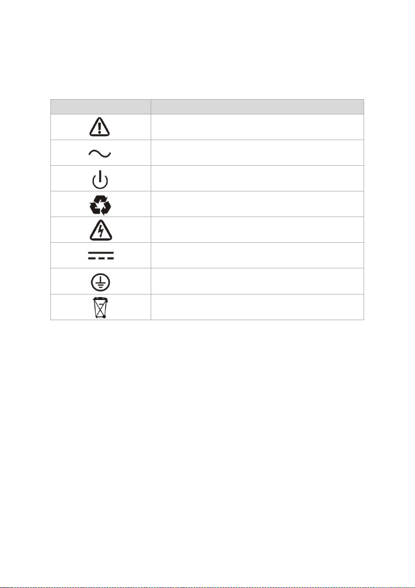
Symbol
Explanation
Alert you to pay special attention
Alternating current source(AC)
Turn on or turn off the UPS
Recycle
Caution of high voltage
Direct current source(DC)
Protective ground
Do not dispose with ordinary trash
2. Descriptionof Commonly Used Symbols
Some or all of the following symbols may be used in this manual. It is advisable to
familiarize yourself with them and understand their meaning:
3. Introduction
This On-Line series is an uninterruptible power supply
incorporatingdouble-converter technology. It provides perfect protection
specificallyfor computer equipment, communication servers, and data centers.
The double-converter principle eliminates all mains power disturbances. A rectifier
converts the alternating current from the mains power to direct current. On the
basis of this DC voltage, the invertergenerates an AC sinusoidal voltage, which
constantly supplies theloads. In the event of power failure, the maintenance-free
batteriespower the inverter.
This manual covers the UPS listed as follows. Please confirm whetherit is the
model you intend to purchase by performing a visual inspectionof the Model No. on
the rear panel of the UPS.
4
Page 7
Model No.
Type
Model No.
Type
OLS6000EC
Standard
OLS6000ECXL
Extended
backup time
OLS10000EC
OLS10000ECXL
"XL"Model: Extended backup time.
3.1. Feature
This series UPS provides theoutstanding reliability, and most cost-performance
ratio in the industrial.Thebenefitsinclude:
True online double-conversion technology with high powerdensity, frequency
Selectable ECO mode, operating with 96% efficiency.
Operate with high input power factor (more than 0.99) and high efficiency(more
5
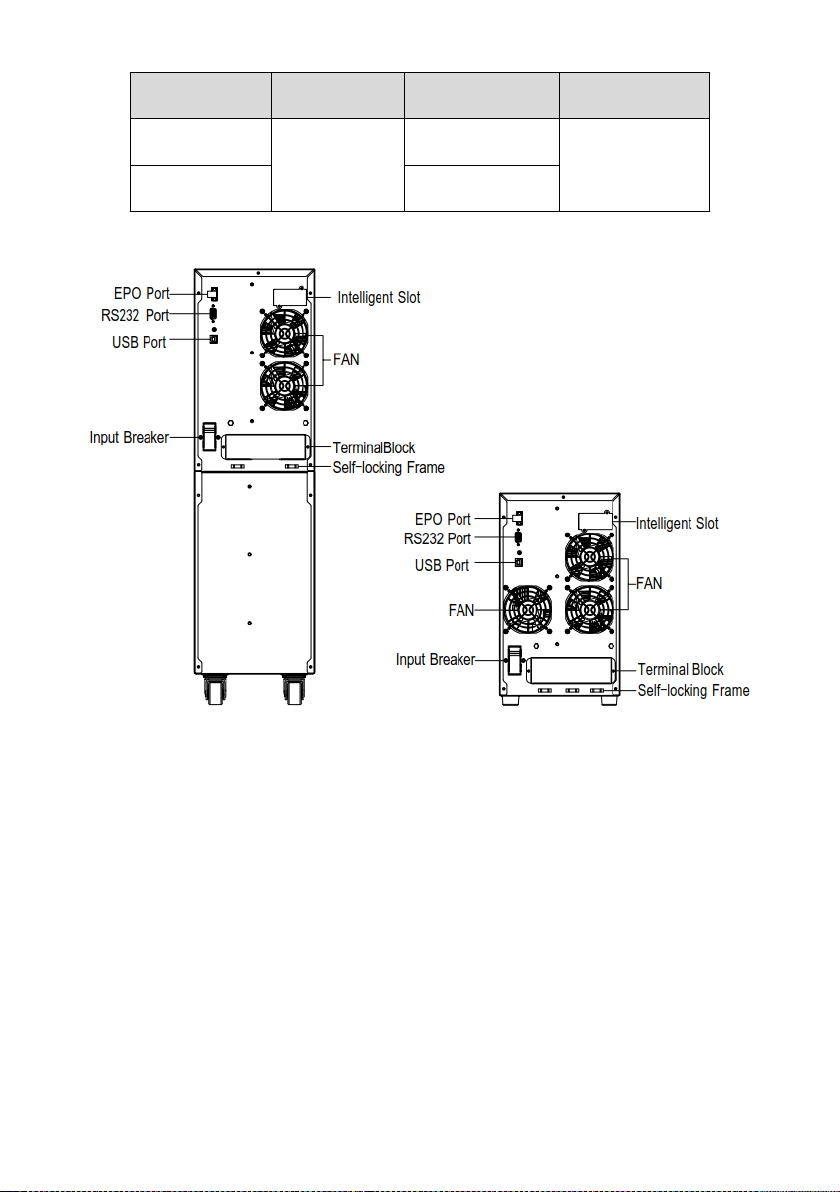
OLS6000EC/OLS10000EC OLS6000ECXL/OLS10000ECXL
Fig.3-1 UPS rear view
independenceand generator compatibility.
than 92%);it could save power and wiring expense.
Page 8

Input
Model NO.
OLS6000EC(XL)
OLS10000EC(XL)
Phase
Single
Voltage Range
110~276Vac(Depends on load level)
Frequency Range
(45~55)/(54~66)Hz
Rated Current
31(36)A
50(55)A
Power Factor
≥0.99@full load
Battery
Rated Voltage
192Vdc
Rated Current
31A
51A
Output
Power Rating
6kVA/4.8kW
10kVA/8kW
Voltage*
208/220/230/240Vac
Frequency
Synchronized50/60×(1±10%)Hz @Line mode
50/60×(1±0.1%)Hz @Battery mode
Wave Form
sine
Load Type
PF 0.5~1, lagging
THDV
≤ 2% @ full linear load
≤ 5% @ full nonlinear load
With perfect output sinewaveform;output power factor is 0.8.It is suitablefor
almost all critical equipment.
Outstanding adaptability to the worst mains input condition.Extra wide input
voltage, frequency range, and sine waveform could avoiddissipating limited
battery energy.
3.2. Electrical Specifications
6
Page 9

Overload**
Line Mode:1min105%~125%
30s125%~135%
1s135%~150%
0.1s>150%
Battery Mode: 1 min105%~125%
30s125%~135%
1s>135%
Temperature
Humidity
Altitude
Storage temperature
0℃~40℃
<95%
<1000m
-15℃~50℃
Model No.
Dimensions W×H×D(mm)
Net Weight (kg)
OLS6000EC
196x702x412
54kg
OLS6000ECXL
196x342x412
15kg
OLS10000EC
196x702x412
63.5kg
OLS10000ECXL
196x342x412
16.4kg
*The load capacity would be derated to 90% automatically when the output voltage
is adjusted to 208Vac.
**Theoverload capacitywould be deratedautomatically in Line mode while
theambienttemperature is larger than 35 degree.
3.3. Operating Environment
Note:The load capacity should be derated 1% every 100m heightened on the basis
of 1000m.
3.4. Dimensions and Weights
7
Page 10

The system must be installed and wired only by qualified electricians
inaccordance with applicable safety regulations.
For safety, please cut off the mains power switch before installation.
When installing the electrical wiring, please note the nominal amperage
of your incoming feeder.
4. Installation
UPS
User’s manual
USB cable
RS-232 cable (optional)
*PowerPanel® Business Edition software is available on our website. Please
visit www.cyberpower.com and go to the Software Section for free download.
CAUTION!Inspect the appearance of the UPS to see if there is any damageduring
transportation. Do not turn on the unit and notify the carrierand the dealer
immediately if there is any damage or lack.
4.1. Power WiresInstallation
4.1.1. Notes forInstallation:
1) The UPS must be installed in a location with good ventilation, faraway fromwater,
inflammable gas and corrosive agents.
2) Ensure the air vents on the front and rear of the UPS are notblocked. Allow at
least 0.5m of space on each side.
3) Condensation to water drops may occur if the UPS is unpacked in avery low
temperature environment. In this case, it is necessary towait until the UPS is
fully dried inside out before proceedinginstallation and use. Otherwise there are
hazards of electric shock.
8
Page 11

Model
OLS6000EC(XL)
OLS10000EC(XL)
Protective earth conductor
Minimum cross section
6mm²
(UL1015 10AWG)
10 mm²
(UL1015 8AWG)
Input L, N
Minimum conductor cross section
6mm²
(UL1015 10AWG)
10 mm²
(UL1015 8AWG)
Input breaker
40A/250Vac
63A/250Vac
External Battery Cabinet
Positive Pole(+), Negative Pole(-),
Minimum conductor cross section
6mm²
(UL1015 10AWG)
10 mm²
(UL1015 8AWG)
External Battery Cabinet Fuse
in Positive Pole(+), Negative Pole(-)
40A/192Vdc
60A/192Vdc
External Battery Cabinet Breaker in
Positive Pole(+), Negative Pole(-)
40A/192Vdc
60A/192Vdc
Torque for fixing above terminals
3.95~4.97Nm (35~44 1b in)
AC Contactor
Coil Remotes Swith
Mains
Input
Input Mains
Breaker
L
N
UPS
4.1.2. INSTALLATION
Use cable cross section and protective device specification:
1) It is suggested to install an external isolating device against current backfeed
between mains input and UPS. After the device is installed, it must add a
warning label with the following wording or the equivalent on the external AC
contactor: RISK OF VOLTAGE BACKFEED. Isolate the UPS before operating
on this circuit, then check for hazardous voltage between all terminals.
2) No matter the UPS is connected to the mains power or not, the output of the
UPS may be electrically live. The parts inside the unit may still have hazardous
9
Fig.4-1 Typical external isolating device installation
Page 12

Output Ground
Input Ground
Input N
Input L
Output L
Output N
NL N
L
INPUT OUTPUT
6000/10000
Note: Make sure that the input, output wires andthe input, outputterminals are
connected tightly.
voltage after turning off the UPS. To make the UPS without output, turn off the
UPS, and cut off the mains power supply, wait the UPS shut down completely,
finally remove the battery connection.
3) Open the terminal block cover located on the rear panel of UPS; please refer
to the appearancediagram.
4) For 6000(XL), it is recommended to select the UL1015 10AWG (6mm²) or
other insulated wire which complies with AWG Standard for the UPS input and
output wirings.
5) For 10000(XL), it is recommended to select the UL1015 8AWG (10 mm²) or
other insulated wire which complies with AWG Standard for the UPS input and
output wirings.
6) Ensure the capacity of mains power supply. Do not use the wall receptacle as
the input power source for the UPS, as its rated current is less than the UPS’s
maximum input current. Otherwise the receptacle may be burned and
destroyed.
7) The protective earth ground wire should be installed first according to the
following diagram. It is better to use green wire or green wire with yellow ribbon
wire.
8) Connect other input and output wires to the corresponding input and output
terminals according to the following diagram.
10
Page 13

Fig.4-2 Input and output Terminal Block wiring diagram
9) It is requested to use the accessorial terminal splices which can be compacted
on the wires tightly to ensure the connection between the wires and the
terminal block is reliable.
10) Install an output breaker between the output terminal of UPS and the load. The
breaker should be with leakage current protective function if necessary.
11) Turn off all the loads first before connecting the load with the UPS, then
perform the connection and finally turn on the loads one by one.
12) After completing the installation, please check the wires to make sure all were
connectedcorrectly and tightly.
13) It is recommendedto charge the batteries for 8 hours before use. After
Installation, turn on the mains power switch and turn the input breaker in the
"ON"position, the UPS will charge the batteries automatically. It can also use
the UPS immediately without charging the batteries, but the backup time may
be less than the standard value.
14) Please note that the start-up power consumption of theinductance load is large,
it may cause the UPS to fail easily. Therefore, if it is necessary to connect the
inductance load such as a laser printer to the UPS, the start-up power should
be used for calculating the capacity of the UPS.
11
Page 14

4.2. External Battery PackInstallation
1. The nominal DC voltage of external batterypack is 192Vdc. To achieve longer
backup time, it is possibletoconnect multi-battery packs, but the principle of
"same voltage,same type"should be strictly followed.
2. For OLS6000ECXL, select the UL1015 10AWG (6mm²)respectively or
otherinsulated wire which complies with AWG Standard for the UPSbattery
wirings.
3. For OLS10000ECXL, select the UL10158AWG (10mm²)respectively or
otherinsulated wire which complies with AWG Standard for the UPSbattery
wirings.
4. The external battery pack must be independent for each UPS. It isforbidden
that two UPS use one external battery pack.
5. The installation step of battery pack should be complied with strictly. Otherwise,
it may encounter the hazard of electric shock.
1) Ensure the UPS is not powered on and the mains input breaker is set at the
"OFF"position.
2) A DC breaker must be installed between the external batterypack and the
UPS. The capacity of breaker must be not lessthan the data specified in the
general specification.
3) Set the external battery pack breaker at"OFF"position andconnect the
16pieces of batteries in series.
4) Connect the external battery pack to the battery terminals.Check the polarity
of connection is correct.
5) Set breaker of the battery pack at the "ON" position.
6) Set the mains input breaker at the "ON" position, the UPSwould power on
and start to charge the battery pack.
4.3. EPO Connection
EPO (Emergency power off): when the emergency occurs, such as the failure of
load, the UPS can cut off the output at once by operating the EPO port manually.
The connection:
Normally the EPO connector is closed with a wire on the rear panel (Fig.4-4), which
is supplied in the accessory. Once the connector is open, the UPS would stop the
output and enter EPO status (Fig.4-3).
12
Page 15

Fig.4-3 Enable the EPO status Fig.4-4 Disable the EPO status
To recover to normal status, first EPO connector should be closed (Fig.4-4), and
press button more than 1 second to clear EPO status, thenUPS would stop
alarm and recover to Bypass mode. And UPS needsbe turned on by manual
operation.
5. Operation
5.1. Panel Display and Control
Fig.5-1 LED Panel
13
Page 16

Control button functions:
Button Description
Press this button for 1second to turn onthe UPS.
Press this button for 3seconds to turn offthe UPS.
Press this button for1secondto display Load Capacity,
BatteryCapacity, Warning and Fault Information alternatively.
Press this button for 3seconds to switch operation mode of UPS.
Selectable options are as below,
(1) Line mode [Default]; beep once
(2) ECO mode; beep twice
(3) Manual Bypass; beep thrice
Buzzer alarm can be enable/disable by pressing button for more than
1second.
Buzzer alarm ON: beep once; Buzzer alarm OFF: beep twice.
Press this button for 2 seconds toactivate the battery self-test
function.
Press buttonsF1+F2 for 2seconds to enable[Default]/disable Site
+
Wiring Fault function.
Function ON: beep once;Function OFF: beep twice.
LED definition:
LED Indicators UPS Status LED Indicators UPS Status
Standby Mode
NORMAL BATTERY BYPASS FAULT
★
(UPS is charging
without output)
NORMAL BATTERY BYPASS FAULT
Line Mode
NORMAL BATTERY BYPASS FAULT
NORMAL BATTERY BYPASS FAULT
NORMAL BATTERY BYPASS FAULT
Battery Mode
Battery Test
Fault
●: Lightened constantly★: Flashing
14
NORMAL BATTERY BYPASS FAULT
NORMAL BATTERY BYPASS FAULT
NORMAL BATTERY BYPASS FAULT
★
Bypass Mode
ECO Mode
Warning
Page 17

▲: Depended on the fault/warning status or other status
Battery capacity and load capacity define
LED Indicators Description LED Indicators Description
Load capacity
< 20%
Load capacity
20 ~ 39%
Load capacity
40 ~ 59%
Load capacity
60 ~ 79%
Load capacity
80 ~ 100%
Battery capacity
< 20%
Battery capacity
20 ~ 39%
Battery capacity
40 ~ 59%
Battery capacity
60 ~ 79%
Battery capacity
80 ~ 100%
●: Lightened constantly
15
Page 18

UPS condition
Buzzer status
Fault active
Continuous
Warning active
Beep every second
Battery mode
Beep every 4 seconds, if battery low, buzzer beep every second
Bypass mode
Beep every 2 minutes
Overload
Beep twice every second
Alarm definition:
5.2. Turn On/Off UPS
Attention: The UPS could only be turned on while connecting to the mains at the
first time.
Attention: Please switch off the connected loads first before turning onthe UPS.
Then switch on the loads one by one after the UPS is turned on.
Turn on UPS:
1) Verify that the UPS terminal block is connected to AC source.
2) Check the breaker of the external battery pack is at"ON" position.
3) Set input breaker to the “ON” position. Meanwhile, the fan begins torotate.
LED1 - LED7 will flash 3 times.
4) Pressthebutton for at least 1 second,the buzzer will beep for 1second,
UPS starts to turn on. After a few seconds later, the UPS turns into Line Mode.
5) Verify that the LED indicator “NORMAL”illuminates solid, indicating that the
UPS is operating normally andpowering the output.
6) If the mains power is abnormal, the UPS will transfer to Battery Mode. When
the mains power returns, the UPS transfers to Line mode.
Turn off UPS:
1) Press the button for at least 3seconds, the UPS transfers to Standby mode,
and the buzzer will beep for 3seconds.
16
Page 19

5.3. Operating Modes
The front panel indicates the UPS status through the LED indicators. Please see
“5.1 Panel Display and Control”.
Standby Mode
When the UPS is turned off and remainsconnected to the mains power, the UPS is
charging without output.
Line Mode
The UPS is powered from the utility.The UPS charges the batteries asneeded and
provides filtered power protection to yourequipment.
Battery Mode
When the mains power is abnormal, the UPS will transfer to battery mode, the
necessary energy is provided by the battery, the buzzer beepsonce every 4
seconds and the LED indicator“BATTERY”illuminates solid.If battery capacity
becomes low, buzzer beeps every second. Prepare your equipment for shutdown is
recommended.
Bypass Mode
When the fault has occurred or “Manual Bypass” command has been received, the
UPS will transfer to bypass mode.The power for the load is directly supplied from
mains power and the battery operation is notavailable while the UPS is in bypass
mode. Please note that your equipment is not protected in bypass mode. The
buzzer beeps every 2 minutes and the LED indicator“BYPASS”illuminates solid.
ECO Mode
ECO mode could be set through the function button on front panel or monitoring
software.When UPS is operating in ECOmode, the power for the load is directly
supplied from the mains power via internal filter while the utility power is in normal
range, the efficiency will up to 96% to save power for the user and the equipment
will be protected as well. Once the mains power is abnormal, the UPS would
transfer to line mode or battery mode and the load is supplied continuously. The
transfer time of UPS output from ECO mode to Battery mode is less than 10ms.
Converter Mode
In converter mode, the UPS would flexibility operate with fixed output
frequency(50Hz or 60Hz). Once the mains power is abnormal, the UPS would
transfer to battery mode and the load is supplied continuously. The function could
be set through the monitoring software.
17
Page 20

6. Trouble Shooting
If some fault or warning occurs in the UPS, please attempt to solve the problem
using the table below. If theproblem still persists, please consult your dealer.
6.1. WarningIndication
LED Indicators Buzzer Possible Cause Solution
Check the loads and
Beep every
second
Overload
remove some
non-critical loads;
Check if some loads
are failed.
Beep every
second
Beep every
second
Beep every
second
Beep every
second
Battery is over
charged
Fan blocked or
disconnected
The charge fails Consult dealer
The ground wire is
disconnected, or
phase and neutral
conductor at input of
UPS system are
reversed
Consult dealer
Check the fan status
Check the Ground
wire status; Reverse
mains power wiring
●: Lightened constantly★: Flashing
18
Page 21

Beep every
second
Beep every
second
Beep every
second
Beep every
second
EPO connector is
open
Inside temperature
of UPS is too high
Battery is
disconnect
Battery voltage is
low
Check the EPO
connector status.
Check the ventilation
of UPS and the
ambient temperature
Do the battery test to
confirm;
Check the battery
bank is connected to
the UPS;
Check the battery
breaker is turn on
When audible alarm
soundingevery
second, battery is
almostempty
Beep every
second
Beep every
second
●: Lightened constantly★: Flashing
19
The
ambienttemperature
is too high
Input fuse break
Check the
environment
ventilation
Check the input fuse
status
Page 22

6.2. Fault Indication
LED Indicators
Buzzer
Possible Cause
Solution
Beep
Continuous
Output short circuit
Remove all the loads. Turn
off theUPS. Check if UPS
output and loads is short
circuit.Ensure short circuit
is removed before turning
on again.
Beep
Continuous
Over Load
Check the loads and
removesome non-critical
loads;
Check if some loads are
failed.
Beep
Continuous
Inside temperature
of UPS is too high
Check the ventilation of
UPSand the ambient
temperature.
Beep
Continuous
The load is pure
inductiveand
capacitive
Remove some non-critical
loads;
Bypass supplies the load
first, ensure there is no
overload, then turn on UPS
Beep
Continuous
Fan blocked or
disconnected over
time
Check the fan status.
Beep
Continuous
UPS internal fault
Consult dealer
●: Lightened constantly★: Flashing
20
Page 23

Beep
Continuous
UPS internal fault
Consult dealer
Beep
Continuous
UPS internal fault
Consult dealer
Beep
Continuous
UPS internal fault
Consult dealer
Beep
Continuous
UPS internal fault
Consult dealer
Beep
Continuous
UPS internal fault
Consult dealer
Beep
Continuous
UPS internal fault
Consult dealer
Beep
Continuous
UPS internal fault
Consult dealer
●: Lightened constantly★: Flashing
21
Page 24

Beep
Continuous
UPS internal fault
Consult dealer
●: Lightened constantly★: Flashing
Problem
Possible cause
Remedy
No indication, no warning
tone even though system
is connected to mains
power supply
No input voltage
Check the building wiring andinput
cable;
Check if the input breaker is closed.
BYPASS LED light up
even though the power
supply is available
Inverter not switched
on
Press button to turn onUPS.
BATTERY LED lights
up, and audible alarm
sounding every 1 beep
in every 4 seconds
Input voltage and/or
frequency are out of
tolerance
Check input power source;
Check the building wiring andinput
cable;
Check if the input breaker isclosed.
Emergency supply
period shorter than
nominal value
Batteries not fully
charged / batteries
defect
Charge the batteries for at least
12 hours and then checkcapacity.
6.3. Others
Please have the following information at hand before calling theAfter-Sales Service
Department:
1) Model number, serial number.
2) Date on which the problem occurred.
3) LEDs display information, Buzzer alarm status.
4) Mains power condition, load type and capacity, environment temperature,
ventilation condition.
5) The information (battery capacity, quantity) of external battery packif the UPS
is "XL" model.
22
Page 25

7. Battery Maintenance
Battery replacement should be performed by qualified personnel.
The battery used for standard models are value regulated sealed
lead-acidmaintenance free battery. Please charge the UPS regularly in order
tomaximize the expected life of the battery. When being connectedto the utility
power, whether the UPS is turned on or not, the UPSkeeps charging the
batteries and also offers the protectivefunction of overcharging and
over-discharging.
The UPS should be charged once every 4 to 6 months if it has notbeen used
for a long time.
In the regions of hot climates, the battery should be charged anddischarged
every 2 months. The standard charging time shouldbe at least 12 hours.
Under normal conditions, the battery life lasts 3 to 5 years. Incase if the battery
is found not in good condition, earlierreplacement should be made. Battery
replacement should beperformed by qualified personnel.
Replace batteries with the same quantity and same type ofbatteries.
Do not replace the battery individually. All the batteries should bereplaced at
the same time following the instructions of the batterysupplier.
If the battery service life (3~5 years at 25°C ambienttemperature) has been
exceeded, the batteries must be replaced.
8. Communication Port
8.1. USBPort
The USB port is compliance with USB 1.1 protocol for its communication software.
8.2. RS232 Interface
The RS232 port is available for UPS monitoring, control, and firmware updates.
8.3. Intelligent Slot
This series is equipped with an intelligent slot for other optional card to achieve
remote management of the UPS through internet / intranet. Please contact your
local distributor for further information.
23
Page 26

Entire contents copyright ©2018CyberPower Systems Inc., All rights reserved.
Reproduction in whole or in part without permission is prohibited. PowerPanel®
Business Edition and PowerPanel® Personal Edition are trademarks of CyberPower
Systems Inc.
24
 Loading...