

CyberPower OLS2000EC/XL, OLS3000EC/XL, OLS1000EC/XL User Manual

User’s Manual
OLS1000EC/XL
OLS2000EC/XL
OLS3000EC/XL
CyberPower Systems Inc.
www.cyberpower.com
K01-C000236-03

IMPORTANT SAFETY INSTRUCTIONS
1
This manual contains important instructions. Please read and follow all instructions carefully during installation and operation of the
unit. Read this manual thoroughly before attempting to unpack, install, or operate the UPS.
CAUTION! The UPS must be connected to a grounded AC
power outlet with fuse or circuit breaker protection. DO NOT
plug the UPS into an outlet that is not grounded. If you need to
power-drain this equipment, turn off and unplug the unit.
CAUTION! The battery can power hazardous components
inside the unit, even when the AC input power is disconnected.
CAUTION! The UPS should be placed near the connected
equipment and easily accessible.
CAUTION! To prevent the risk of fire or electric shock, install
in a temperature and humidity controlled indoor area, free of
conductive contaminants. (Please see specifications for
acceptable temperature and humidity range).
CAUTION! (No User Serviceable Parts): Risk of electric
shock, do not remove cover. No user serviceable parts inside.
Refer servicing to qualified service personnel.
CAUTION! (Non-Isolated Battery Supply): Risk of electric
shock, battery circuit is not isolated from AC power source;
hazardous voltage may exist between battery terminals and
ground. Test before touching.
CAUTION! To reduce the risk of fire, connect the UPS to a
branch circuit with 10 amperes (OLS1000EC / OLS2000EC) /
16 amperes (OLS3000EC) maximum over-current protection in
accordance to CE requirement.
CAUTION! The AC outlet where the UPS is connected should
be close to the unit and easily accessible.
CAUTION! Please use only VDE-tested, CE-marked mains
cable, (e.g. the mains cable of your equipment), to connect the
UPS to the AC outlet.
CAUTION! Please use only VDE-tested, CE-marked power
cables to connect any equipment to the UPS.
CAUTION! When installing the equipment, ensure that the
sum of the leakage current of the UPS and the connected
equipment does not exceed 3.5mA.
CAUTION! The OLS1000EC / OLS2000EC / OLS3000EC / XL
/ Battery module models are only qualified maintenance
personnel may carry out installations.
CAUTION! Do not unplug the unit from AC Power during
operation, as this will invalidate the protective ground
insulation.
CAUTION! To avoid electric shock, turn off and unplug the
unit before installing the input/output power cord with a ground
wire. Connect the ground wire prior to connecting the line
wires!
CAUTION! Do not use an improper size power cord as it may
cause damage to your equipment and cause fire hazards.
CAUTION! Wiring must be done by qualified personnel.
CAUTION! DO NOT USE FOR MEDICAL OR LIFE
SUPPORT EQUIPMENT! Under no circumstances this unit
should be used for medical applications involving life support
equipment and/or patient care.
CAUTION! DO NOT USE WITH OR NEAR AQUARIUMS!
To reduce the risk of fire, do not use with or near aquariums.
Condensation from the aquarium can come in contact with
metal electrical contacts and cause the machine to short out.
CAUTION! Do not dispose of batteries in fire as the battery
may explode.
CAUTION! Do not open or mutilate the battery, released
electrolyte is harmful to the skin and eyes.
CAUTION! A battery can present a risk of electric shock and
high short circuit current. The following precaution should be
observed when working on batteries
1. Remove watches, rings or other metal objects.
2. Use tools with insulated handles.
CAUTION! The unit has a dangerous amount of voltage.
When the UPS indicators is on, the units may continue to
supply power thus the unit’s outlets may have a dangerous
amount of voltage even when it’s not plugged in to the wall
outlet.
CAUTION! Make sure everything is turned off and
disconnected completely before conducting any maintenance,
repairs or shipment.
CAUTION! Connect the Protection Earth (PE) safety
conductor before any other cables are connected.
WARNING! (Fuses): To reduce the risk of fire, replace only
with the same type and rating of fuse.
DO NOT INSTALL THE UPS WHERE IT WOULD BE
EXPOSED TO DIRECT SUNLIGHT OR NEAR A STRONG
HEAT SOURCE!
DO NOT BLOCK OFF VENTILATION OPENINGS AROUND
THE HOUSING!
DO NOT CONNECT DOMESTIC APPLIANCES SUCH AS
HAIR DRYERS TO UPS OUTPUT SOCKETS!
SERVICING OF BATTERIES SHOULD BE PERFORMED OR
SUPERVISED BY PERSONNEL KNOWLEDGE OF
BATTERIES AND THE REQUIRED PRECAUTIONS. KEEP
UNAUTHORIZED PERSONNEL AWAY FROM BATTERIES!
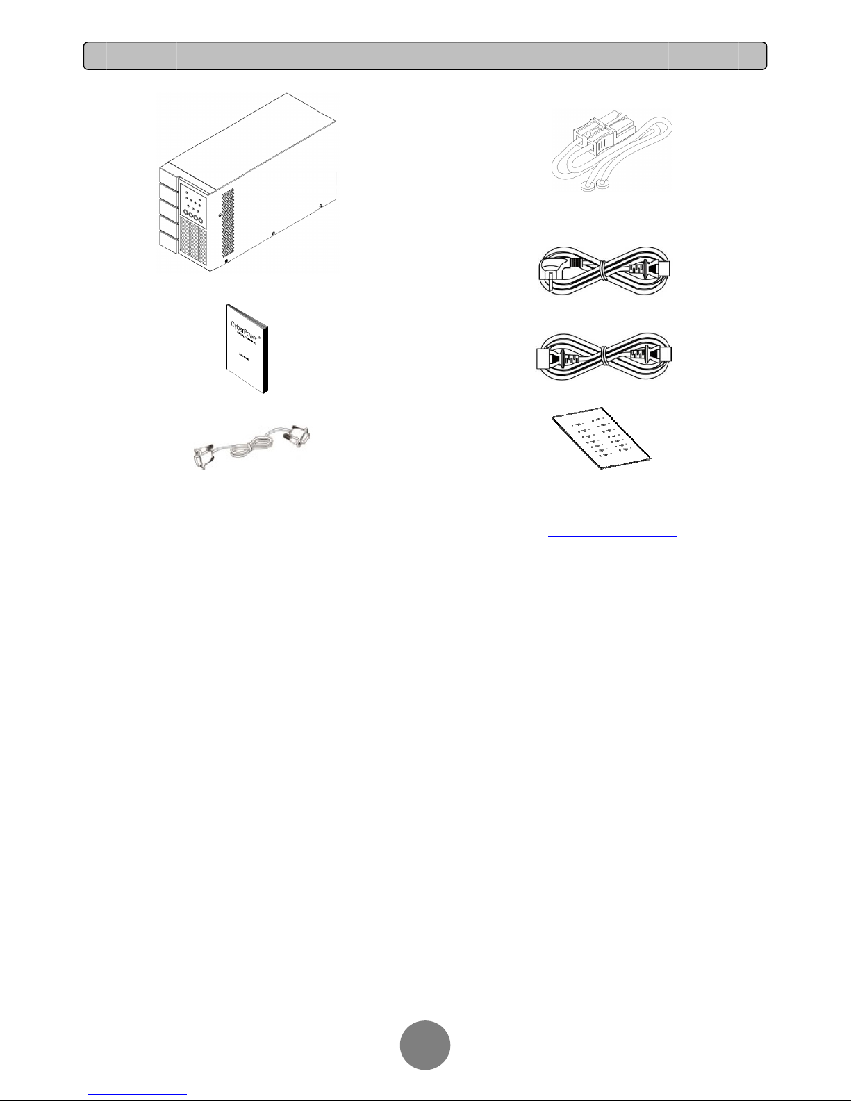
RS23
2UP
User’s
2
communica
t
S
manual
ion cable(Op
t
U
ional)
NPACKI
N
2
Po
wweb
Sof
t
G
Batte
Outp
u
erPanel® Bu
site. Please
v
ware Section
ry cable (for l
o
Input p
o
t power cord
(
Warra
n
siness Editio
n
isit www.cy
b
for free dow
n
ng-run mode
wer cord
for IEC Mod
e
ty Card
software is
a
erpower.co
m
load.
ls only)
ls only)
vailable on o
u
and go to t
h
r
e
INSTALLING YOUR UPS SYSTEM
3
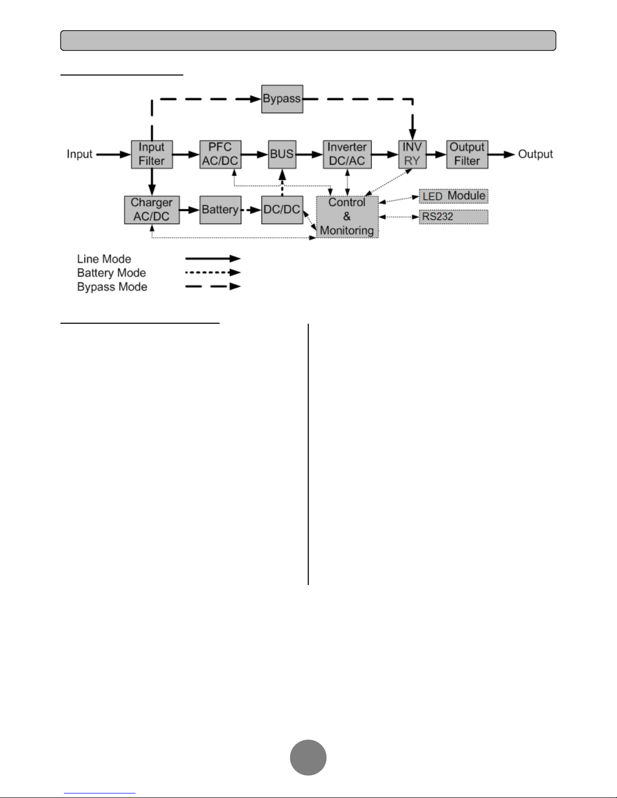
SYSTEM BLOCK DIAGRAM
HARDWARE INSTALLATION GUIDE
1.
Battery charge loss may occur during shipping and storage.
Before using the UPS, it’s strongly recommended to charge
batteries for four hours to ensure the batteries’ maximum
charge capacity. To recharge the batteries, simply plug the UPS
into an AC outlet.
2. When using the included software, connect the serial cable
between the computer and the corresponding port on the UPS.
3. Connect your computer, monitor, and any
externally-powered data storage device (Hard drive, Tape drive,
etc.) into the outlets only when the UPS is off and unplugged.
DO NOT plug a laser printer, copier, space heater, vacuum,
paper shredder or other large electrical device into the UPS.
The power demands of these devices will overload and
possibly damage the unit.
4. Press the ON switch to turn the UPS on. If an overload is
detected, an audible alarm will sound and the UPS will
continuously emit one beep per second. For resetting the unit,
unplug some equipment from the outlets. Make sure your
equipment carries a load current within the unit’s safe range,
(refer to the technical specifications).
5. This UPS is equipped with an auto-charge feature. When the
UPS is plugged into an AC outlet, the battery will automatically
charge, even when the unit is switched off.
6. To maintain an optimal battery charge, leave the UPS
plugged into an AC outlet at all times.
7. Before storing the UPS for an extended period of time, turn
the unit OFF. Then cover it and store it with the batteries fully
charged. Recharge the batteries every three months to ensure
good battery capacity and long battery life. Maintaining a good
battery charge will help prevent possible damage to the unit
from battery leakage.
8. The UPS has one Serial port that allows connection and
communication between the UPS and any attached computer
running the PowerPanel
®
Business Edition Agent software. The
UPS can control the computer’s shutdown during a power
outage through the connection while the computer can monitor
the UPS and alter various programmable parameters.
9. To avoid electric shock, turn the unit OFF and disconnect the
unit from utility power before hardwiring the UPS (in/out power
cord). The in/out power cord MUST be grounded.
BASIC OPERATION
4
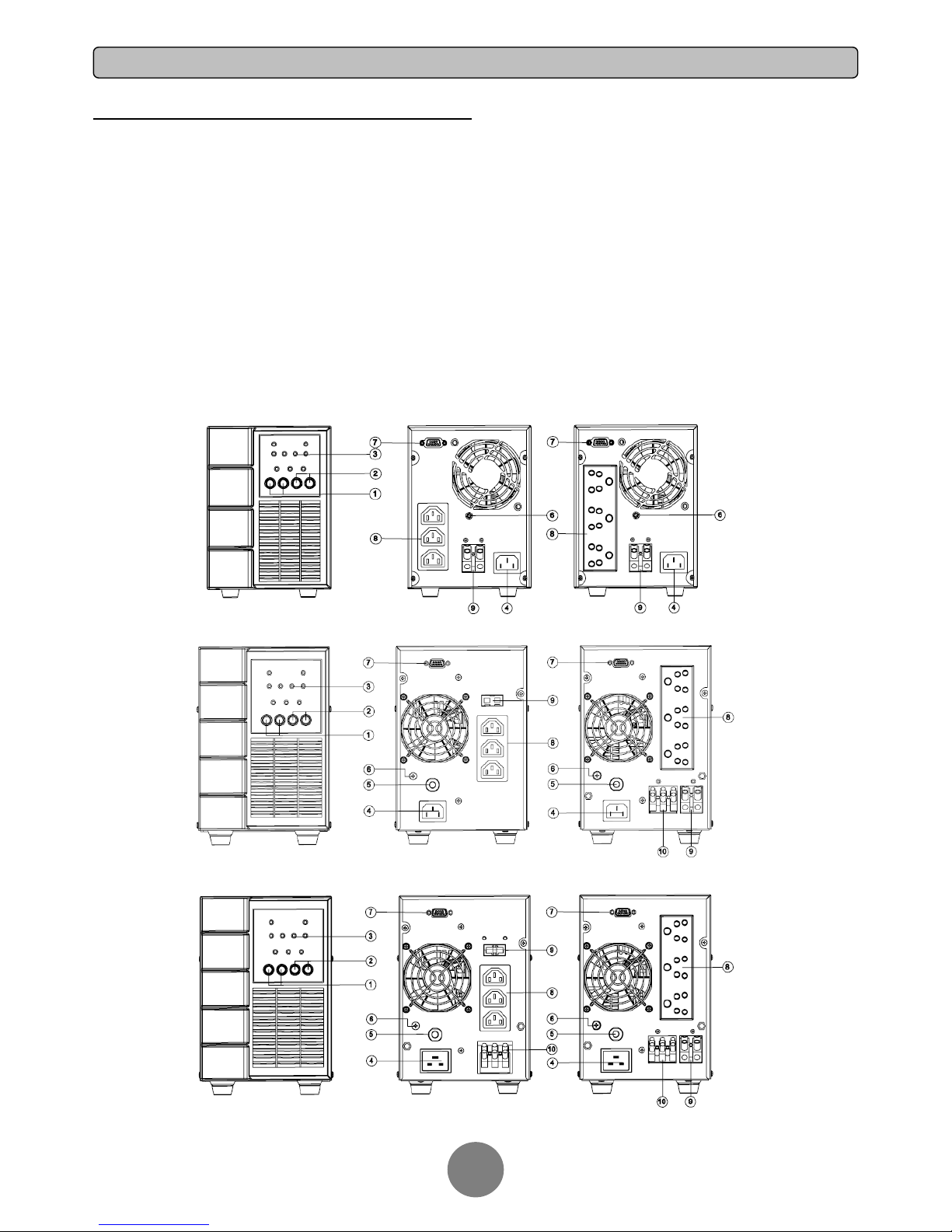
POWER MODULE FRONT/REAR PANEL DESCRIPTION
1. Power On/Off Button
Master ON/OFF for the UPS.
2. Function Buttons
Scroll up, scroll down, and silence.
3. Multifunction LED Display
Indicate status information and events.
4. AC Input Inlet
Connect the AC Power cord to a properly wired and
grounded outlet.
5. Circuit Breaker
Provide overload and fault protection.
6. Screw for XL Battery Cable with ground
Connect the XL Battery Cable and ground.
7. Serial Port
Serial port provides communication between the UPS and the
computer. The UPS can control the computer’s shutdown
during a power outage through the connection while the
computer can monitor the UPS and alter its various
programmable parameters.
8. Battery Backup & Surge Protected Outlets
Provide battery backup and surge protection. They ensure
power is provided to connected equipment over a period of time
during a power failure.
9. Extended Runtime Battery Module Connector (for
long-run models only)
Connect to additional external battery modules.
10. Output Terminal Block
Connect to your equipment.
OLS1000EC/ECXL
OLS2000EC/ECXL
OLS3000ECXL OLS3000EC/ECXL
BASIC OPERATION
5
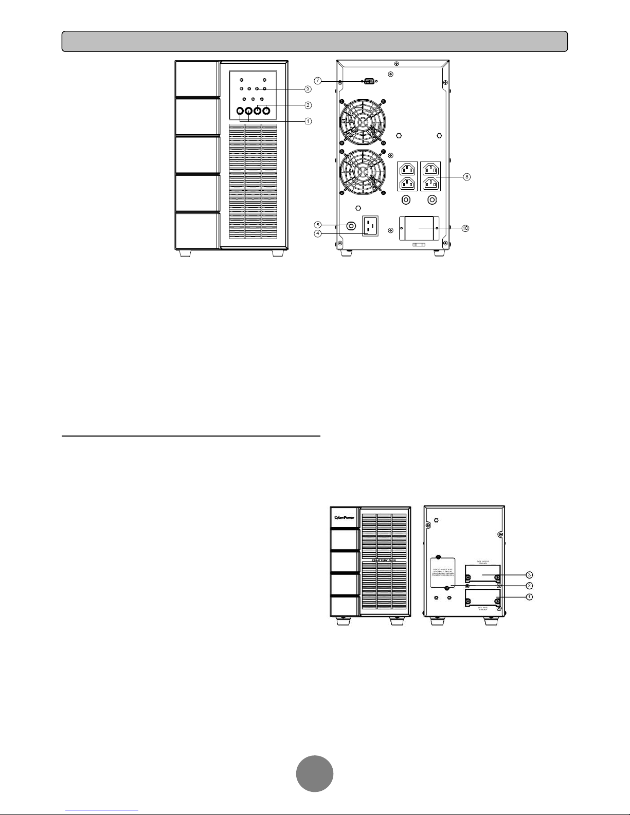
OLS3000EC
BATTERY MODULE FRONT/REAR PANEL DESCRIPTION
1. Input Connector
Use this input connector to daisy chain the next
Battery module. Remove the connector cover
for access.
2. On-board Replaceable Fuse Cover
Replaceable fuse is accessible from the rear
panel. It must be done by qualified personnel.
3. Output Connector
Use this output Connector to connect the
Battery module to the Power module or to the
next Battery module.
BPSE24V45AC/BPSE48V45AC/BPSE72V45AC
 Loading...