

Cyber Power OL1000EXL, OL2000EXL, OL1500EXL, OL3000EXL User Manual

User’s Manual
OL1000EXL
OL1500EXL
OL2000EXL
OL3000EXL
CyberPower Systems Inc.
www.cpsww.com
K01-0000358-00

Copyright © 2014 CyberPower Systems, Inc.
IMPORTANT SAFETY INSTRUCTIONS
1
This manual contains important instructions. Please read and follow all instructions carefully during installation and operation of the unit. Read this manual
thoroughly before attempting to unpack, install, or operate the UPS.
CAUTION! The UPS must be connected to a grounded AC power
outlet with fuse or circuit breaker protection. DO NOT plug the UPS into
an outlet that is not grounded. If you need to power-drain this equipment,
turn off and unplug the unit.
CAUTION! The battery can power hazardous components inside the
unit, even when the AC input power is disconnected.
CAUTION! The UPS should be placed near the connected equipment
and easily accessible.
CAUTION! To prevent the risk of fire or electric shock, install in a
temperature and humidity controlled indoor area, free of conductive
contaminants. (Please see specifications for acceptable temperature and
humidity range).
CAUTION! (No User Serviceable Parts): Risk of electric shock, do
not remove cover. No user serviceable parts inside. Refer servicing to
qualified service personnel.
CAUTION! (Non-Isolated Battery Supply): Risk of electric shock,
battery circuit is not isolated from AC power source; hazardous voltage
may exist between battery terminals and ground. Test before touching.
CAUTION! To reduce the risk of fire, connect the UPS to a branch
circuit with 10 amperes (OL1000 / OL1500 / OL2000) / 16 amperes
(OL3000) maximum over-current protection in accordance to CE
requirement.
CAUTION! The AC outlet where the UPS is connected should be close
to the unit and easily accessible.
CAUTION! Please use only VDE-tested, CE-marked mains cable, (e.g.
the mains cable of your equipment), to connect the UPS to the AC outlet.
CAUTION! Please use only VDE-tested, CE-marked power cables to
connect any equipment to the UPS.
CAUTION! When installing the equipment, ensure that the sum of the
leakage current of the UPS and the connected equipment does not
exceed 3.5mA.
CAUTION! The OL1000 / OL1500 / OL2000 / OL3000 models are only
qualified maintenance personnel may carry out installations.
CAUTION! Do not unplug the unit from AC Power during operation, as
this will invalidate the protective ground insulation.
CAUTION! To avoid electric shock, turn off and unplug the unit before
installing the input/output power cord with a ground wire. Connect the
ground wire prior to connecting the line wires!
CAUTION! Do not use an improper size power cord as it may cause
damage to your equipment and cause fire hazards.
CAUTION! Wiring must be done by qualified personnel.
CAUTION! DO NOT USE FOR MEDICAL OR LIFE SUPPORT
EQUIPMENT! Under no circumstances this unit should be used for
medical applications involving life support equipment and/or patient care.
CAUTION! DO NOT USE WITH OR NEAR AQUARIUMS! To reduce
the risk of fire, do not use with or near aquariums. Condensation from
the aquarium can come in contact with metal electrical contacts and
cause the machine to short out.
CAUTION! Do not dispose of batteries in fire as the battery may
explode.
CAUTION! Do not open or mutilate the battery, released electrolyte is
harmful to the skin and eyes.
CAUTION! A battery can present a risk of electric shock and high short
circuit current. The following precaution should be observed when
working on batteries
1. Remove watches, rings or other metal objects.
2. Use tools with insulated handles.
CAUTION! The unit has a dangerous amount of voltage. When the
UPS indicators is on, the units may continue to supply power thus the
unit’s outlets may have a dangerous amount of voltage even when it’s not
plugged in to the wall outlet.
CAUTION! Make sure everything is turned off and disconnected
completely before conducting any maintenance, repairs or shipment.
CAUTION! Connect the Protection Earth (PE) safety conductor before
any other cables are connected.
WARNING! (Fuses): To reduce the risk of fire, replace only with the
same type and rating of fuse.
DO NOT INSTALL THE UPS WHERE IT WOULD BE EXPOSED TO
DIRECT SUNLIGHT OR NEAR A STRONG HEAT SOURCE!
DO NOT BLOCK OFF VENTILATION OPENINGS AROUND THE
HOUSING!
DO NOT CONNECT DOMESTIC APPLIANCES SUCH AS HAIR
DRYERS TO UPS OUTPUT SOCKETS!
SERVICING OF BATTERIES SHOULD BE PERFORMED OR
SUPERVISED BY PERSONNEL KNOWLEDGE OF BATTERIES AND
THE REQUIRED PRECAUTIONS. KEEP UNAUTHORIZED
PERSONNEL AWAY FROM BATTERIES!
Copyright © 2014 CyberPower Systems, Inc.
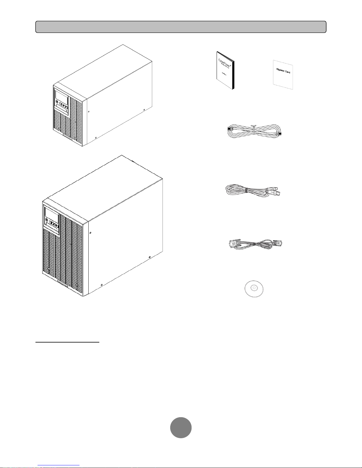
UNPACKING
2
1K/1.5KVA or 2K/3KVA UPS
User’s manual Register card
Phone line
USB communication cable
Serial Interface Cable (RS-232)
PowerPanel® Business Edition software CD
SAFETY PRECAUTIONS
CAUTION! Installation environment should be in a temperature and humidity controlled indoor area free of conductive contaminants. Do not install this UPS
where excessive moisture or heat is present (Please see specifications for acceptable temperature and humidity range).
CAUTION! Never install a UPS, or associated wiring or equipment, during a lightning storm.
CAUTION! Do not work alone under hazardous conditions.
CAUTION! In case of the risk of electric shock, do not remove the top cover.
CAUTION! The battery can energize hazardous live parts inside even when the AC input power is disconnected.

Copyright © 2014 CyberPower Systems, Inc.
INSTALLING YOUR UPS SYSTEM
3
SYSTEM BLOCK DIAGRAM
Output
Input
Filter
PFC
AC/DC
BUS
Inverter
DC/AC
INV
RY
Charger
AC/DC
Bypass
Battery
Output
Filter
Input
Line Mode
Battery Mode
Bypass Mode
Control
&
Monitoring
LCD Module
USB & DB9
SNMP Slot
DC/DC
HARDWARE INSTALLATION GUIDE
1. Battery charge loss may occur during shipping and storage. Before
using the UPS, it’s strongly recommended to charge batteries for four
hours to ensure the batteries’ maximum charge capacity. To recharge the
batteries, simply plug the UPS into an AC outlet.
2. When using the included software, connect either the serial or the
USB cable between the computer and the corresponding port on the UPS.
Note: If the USB port is used, the serial port will be disabled. They cannot
be used simultaneously. After connecting to either the USB port or the
Serial port on the UPS, a computer with the PowerPanel® Business
Edition Agent software installed can control the operating schedule,
battery test, outlets, as well as obtain UPS status information. However,
other computers with PowerPanel® Business Edition Client software can
only obtain UPS status information via LAN connection.
3. Connect your computer, monitor, and any externally-powered data
storage device (Hard drive, Tape drive, etc.) into the outlets only when
the UPS is off and unplugged. DO NOT plug a laser printer, copier, space
heater, vacuum, paper shredder or other large electrical device into the
UPS. The power demands of these devices will overload and possibly
damage the unit.
4. To protect a fax machine, telephone, modem line or network cable,
connect the telephone or network cable from the wall jack outlet to the
jack marked “IN” on the UPS and connect a telephone cable or network
cable from the jack marked “OUT” on the UPS to the modem, computer,
telephone, fax machine, or network device.
5. Press the ON/OFF switch to turn the UPS on. The Power-On indicator
light will display when activated. If an overload is detected, an audible
alarm will sound and the UPS will continuously emit two beeps per
second. For resetting the unit, unplug some equipment from the outlets.
Make sure your equipment carries a load current within the unit’s safe
range, (refer to the technical specifications).
6. This UPS is equipped with an auto-charge feature. When the UPS is
plugged into an AC outlet, the battery will automatically charge, even
when the unit is switched off.
7. To maintain an optimal battery charge, leave the UPS plugged into an
AC outlet at all times.
8. Before storing the UPS for an extended period of time, turn the unit
OFF. Then cover it and store it with the batteries fully charged. Recharge
the batteries every three months to ensure good battery capacity and
long battery life. Maintaining a good battery charge will help prevent
possible damage to the unit from battery leakage.
9. The UPS has one USB port (default) and one Serial port that allows
connection and communication between the UPS and any attached
computer running the PowerPanel® Business Edition Agent software. The
UPS can control the computer’s shutdown during a power outage
through the connection while the computer can monitor the UPS and alter
various programmable parameters. Note: Only one communication port
can be used at a time. The port not in use will automatically become
disabled or the serial port will be disabled if both ports are attached.
10. EPO (Emergency Power Off) Port:
EPO ports allow administrators the capability to connect the UPS unit to
customer-supplied EPO switches. These installations give operators a
single access point to immediately power-off all equipment connected to
the UPS during an emergency.
11. To avoid electric shock, turn the unit OFF and disconnect the unit
from utility power before hardwiring the UPS (in/out power cord). The
in/out power cord MUST be grounded.
Copyright © 2014 CyberPower Systems, Inc.
BASIC OPERATION
4
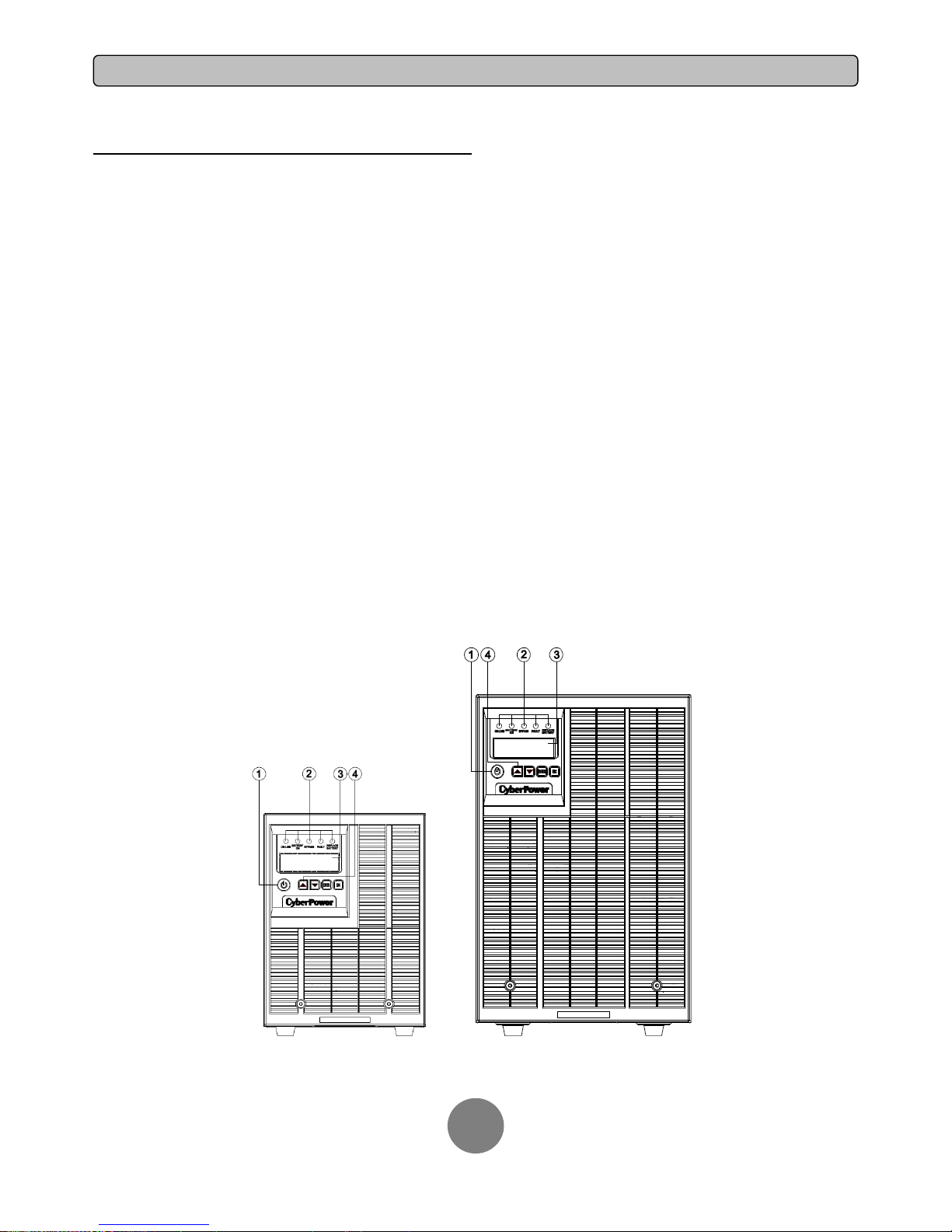
POWER MODULE FRONT/REAR PANEL DESCRIPTION
1. Power Button / Power on Indicator
Master ON/OFF for the UPS. Indicates that the UPS is on and supplying
power.
2. UPS Status / Fault / Replace Battery LED Indicator
Indicates the status of the UPS, displaying whether it is operating in Line,
Battery or Bypass Mode, if it has an internal fault or if the battery needs
to be replaced.
3. Multifunction LCD Readout
Shows UPS status, information, settings and events.
4. Function Buttons
Scroll up, scroll down, select and cancel LCD menu.
5. Input Circuit Breaker
Provides input overload and fault protection.
6. Battery Backup & Surge Protected Outlets
Provides battery backup and surge protection. They ensure power is
provided to connected equipment over a period of time during a power
failure.
Critical / Noncritical Load
Allows the creation of load priorities to ensure that battery power
reserves are transferred to specified outlets during a power outage. The
unit can be programmed to provide additional runtime for equipment
connected to the “CRITICAL” outlets, while stopping the power supply to
equipment connected to “NONCRITICAL” outlets after a designated
period of time.
7. Serial Port
Serial port provides communication between the UPS and the computer.
The UPS can control the computer’s shutdown during a power outage
through the connection while the computer can monitor the UPS and alter
its various programmable parameters.
8. USB port
This is a connectivity port which allows communication and control
between the UPS and the connected computer. It is recommended to
install the PowerPanel® Business Edition Agent software on the
PC/Server connected with the USB cord.
9. Surge Protected Communication Ports RJ-45/RJ-11
These ports are used to protect standard RJ-45/RJ-11 based products
(ADSL, LAN, Phone/ Modem-Lines) and cabling systems from surges.
10. Relay Output Connector
Convert UPS signals into real potential-free Dry Contacts for industrial
control.
11. SNMP/HTTP Network slot
Slot to install the optional SNMP card for remote network control and
monitoring.
12. Extended Runtime Battery Module Connector
Connection for additional CyberPower XL Battery modules.
13. EPO (Emergency Power Off) Connector
Enables an emergency UPS Power-Off from a remote location.
14. AC Input Inlet
Connect the AC Power cord to a properly wired and grounded outlet.
OL1000EXL / OL1500EXL OL2000EXL / OL3000EXL
 Loading...