

Page 1

User’s Manual
CyberPower Systems Inc.
MBP20HVAU3
MBP20HVDE3
MBP20HVIEC6
www.cpsww.com
K01-0000262-02
Page 2

IMPORTANT SAFETY INSTRUCTIONS
1
This manual contains important instructions. Please read and follow all instructions carefully during installation and operation of the unit. Read this manual
thoroughly before attempting to unpack, install, or operate the MBP (Maintenance Bypass PDU).
CAUTION! The MBP must be connected to a grounded AC power
outlet with fuse or circuit breaker protection. DO NOT plug the MBP into
an outlet that is not grounded.
CAUTION! The MBP should be placed near the connected equipment
and easily accessible.
CAUTION! To prevent the risk of fire or electric shock, install in a
temperature and humidity controlled indoor area, free of conductive
contaminants. (Please see specifications for acceptable temperature and
humidity range).
CAUTION! (No User Serviceable Parts): Risk of electric shock, do
not remove cover. No user serviceable parts inside. Refer servicing to
qualified service personnel.
CAUTION! To reduce the risk of fire, connect the UPS to a branch
circuit with 16 amperes maximum over-current protection in accordance
to CE requirement.
CAUTION! The AC outlet where the MBP is connected should be close
to the unit and easily accessible.
CAUTION! Please use only VDE-tested, CE-marked mains cable, (e.g.
the mains cable of your equipment), to connect the MBP to the AC outlet.
CAUTION! Please use only VDE-tested, CE-marked power cables to
connect any equipment to the MBP.
CAUTION! The MBP are only qualified maintenance personnel may carry
out installations.
CAUTION! Do not use an improper size power cord as it may cause
damage to your equipment and cause fire hazards.
CAUTION! Wiring must be done by qualified personnel.
CAUTION! DO NOT USE FOR MEDICAL OR LIFE SUPPORT
EQUIPMENT! Under no circumstances this unit should be used for
medical applications involving life support equipment and/or patient care.
CAUTION! DO NOT USE WITH OR NEAR AQUARIUMS! To reduce
the risk of fire, do not use with or near aquariums. Condensation from the
aquarium can come in contact with metal electrical contacts and cause
the machine to short out.
CAUTION! The unit has a dangerous amount of voltage. When the
MBP indicators is on, the units may continue to supply power thus the
unit’s outlets may have a dangerous amount of voltage even when it’s not
plugged in to the wall outlet.
CAUTION! Make sure everything is turned off and disconnected
completely before conducting any maintenance, repairs or shipment.
CAUTION! Connect the Protection Earth (PE) safety conductor before
any other cables are connected.
CAUTION! Never install a MBP, or associated wiring or equipment,
during a lightning storm.
CAUTION! Do not work alone under hazardous conditions.
CAUTION! Do not unplug the unit from AC Power during operation, as
this will invalidate the protective ground insulation.
CAUTION! To avoid electric shock, turn off and unplug the unit before
installing the input/output power cord with a ground wire. Connect the
ground wire prior to connecting the line wires!
DO NOT INSTALL THE MBP WHERE IT WOULD BE EXPOSED TO
DIRECT SUNLIGHT OR NEAR A STRONG HEAT SOURCE!
DO NOT CONNECT DOMESTIC APPLIANCES SUCH AS HAIR
DRYERS TO MBP OUTPUT SOCKETS!
Copyright © 2012 CyberPower Systems, Inc.
Page 3
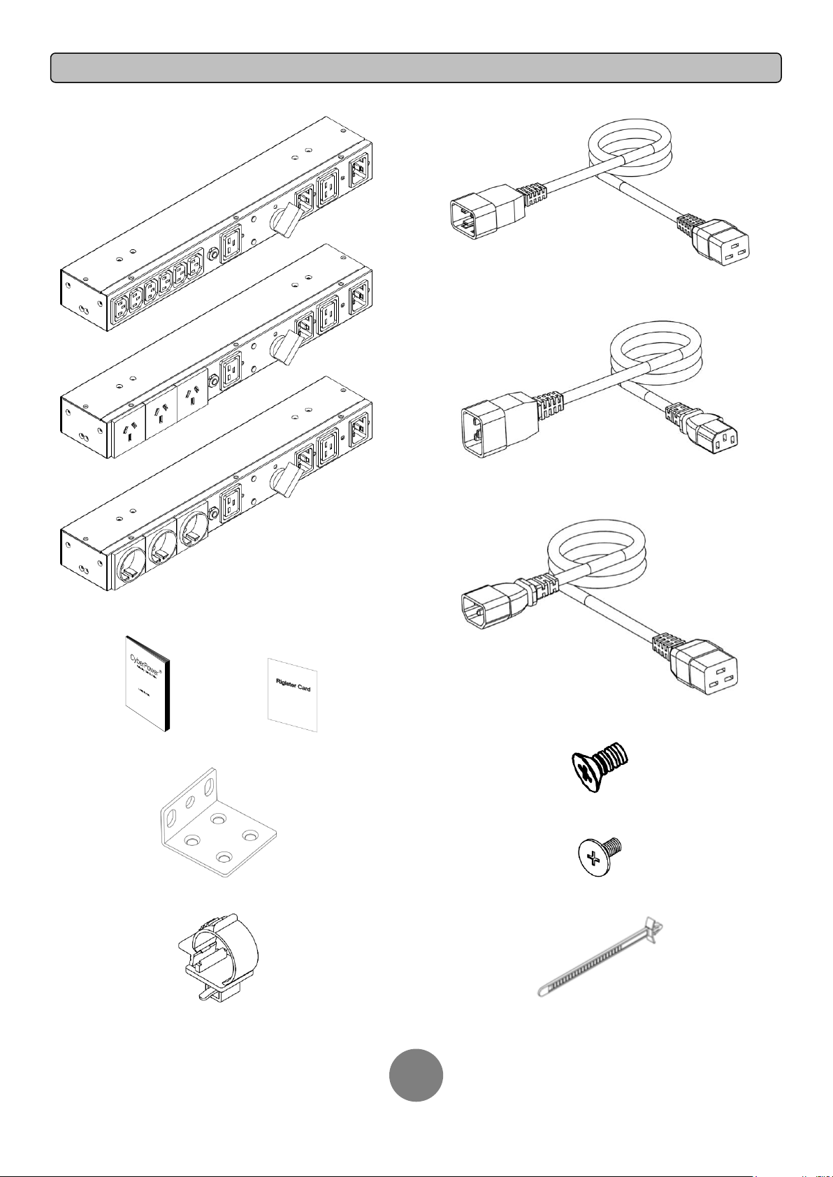
UNPACKING
2
C20/C19 Power cords (2)
IEC, AU or DE MBP
(Maintenance Bypass PDU)
User’s manual Register card
Rackmount brackets (2)
C20/C13 Power cord (1)
C14/C19 Power cord (1)
Flat head screws: M4X8L (4)
Pan head screws: M5X12L (4)
Power Cord Retention Clips (4)
Cable Ties (4)
Copyright © 2012 CyberPower Systems, Inc.
Page 4

HARDWARE INSTALLATION
3
○
1
○
2
○
1
○
2
○
1
○
2
○
2
○
1
○
1
○
2
HARDWARE INSTALLATION
These versatile MBP can be mounted in a rackmount or vertical tower orientation.
Please follow the instructions below for the respective mounting methods.
Step 1: Brackets installation
Attach the two brackets to the MBP using the provided screws M4X8L*4pcs.
Step 2: MBP Installation
Secure the MBP with the provided screws M5X12L*2pcs.
MBP mounted horizontally in a rackmount
Wall-mounted
MBP mounted vertically in a rackmount
MBP mounted with UPS in rackmount mode
MBP mounted with UPS in tower mode
Copyright © 2012 CyberPower Systems, Inc.
Page 5

CONNECTING THE INPUT/ OUTPUT
4
C14/C19 Power cord
C13/C20 Power cord
C14/C19 Power cord
C13/C20 Power cord
C19/C20 Power cord
C20/C19 Power cord
INPUT/ OUTPUT CONFIGURATION
Connect the input/output as shown in the following diagram.
1K/1.5K configuration
2K configuration
Copyright © 2012 CyberPower Systems, Inc.
3K configuration
Page 6

INSTALLING/REMOVING THE RETENTION CLIP
5
Flat side
INSTALLING THE RETENTION CLIP
REMOVING THE RETENTION CLIP
Step 1: Cable Tie Installation
Insert the Cable Tie into the hole beside the socket on the MBP. Note the
flat side of the Cable Tie should face to the socket which the power cord
will be inserted.
Step 2: Retention Clip Installation
Place a Retention Clip on the power cord. Insert the power cord to the
MBP. Align and Insert the Cable Tie into the Retention Clip.
Step 1: Loosen Retention Clip
Loosen the Retention Clip by pushing it to the right.
Step 2: Remove Retention Clip
Remove the Retention Clip by pulling the Cable Tie to the right.
Step 3: Fasten Retention Clip
Push the Retention Clip until it touches the plug and fasten the Retention
Clip.
Copyright © 2012 CyberPower Systems, Inc.
Page 7

BASIC OPERATION
6
MBP FRONT PANEL DESCRIPTION
1. AC Output Outlets
Provide output power to the connected equipment. The supplied power
source can be selected by manual bypass switch to ensure nonstop
operation during maintenance or UPS replacement.
2. Output Circuit Breaker
Provide output overload and fault protection.
3. “Normal” LED Indicator
Indicate that the connected equipment is supplied by UPS output.
4. “Bypass” LED Indicator
Indicate that the connected equipment is supplied directly by utility power.
5. Manual Bypass Switch
Provide UPS output to connected equipment when turned to “Normal”,
provide utility power to connected equipment when turned to “Bypass”.
6. “To UPS Output” Inlet
Connect the AC Power cord to UPS Output.
7. “To UPS Input” Outlet
Connect the AC Power cord to UPS Input.
8. “Utility Power” Inlet
Connect the AC Power cord to a properly wired and grounded outlet.
MBP20HVIEC6 MBP20HVAU3 MBP20HVDE3
Copyright © 2012 CyberPower Systems, Inc.
Page 8

MAINTENANCE
7
MAINTENANCE BYPASS PDU OPERATION
This operation allows qualified personnel to remove the MBP from the UPS for routine maintenance or replacement without disrupting power to connected
equipment.
The connected equipment is supplied by
UPS output when the Manual Bypass
Switch is turned to “Normal”.
The connected equipment is supplied by
utility power when the Manual Bypass
Switch is turned to “Bypass”.
CyberPower Systems Inc.
www.cpsww.com
Entire contents copyright© 2012 CyberPower Systems Inc., All rights reserved. Reproduction in whole or in part
without permission is prohibited. PowerPanel® Business Edition and PowerPanel® Personal Edition are trademarks of
CyberPower Systems Inc.
Copyright © 2012 CyberPower Systems, Inc.
 Loading...