

CyberOptics 003 User Manual
8023533 Rev E
CyberOptics
WaferSense® and
ReticleSense®
AMS
User’s Guide
For AMS-300C, AMS-200C, AMS-150C,
and AMSR wireless Auto Multi-Sensors

2
General information ........................................................................................... 6
Introduction ........................................................................................................ 9
Installing the AMS Software ......................................................................... 12
Installing the Wireless Link .......................................................................... 14
Checking the Communications Between the Link and the AMS ................... 15
Registering Your AMS for Calibration Service ............................................... 16
Running the MultiView Application ............................................................. 17
Technical Support ........................................................................................ 19
Using Your AMS ................................................................................................ 21
Opening and Closing the Charging Case ....................................................... 22
Using the AMS Controls ............................................................................... 23
Using the AMS Indicators ............................................................................. 23
Using the Vibration, Humidity, and Leveling Tabs ........................................ 24
Changing Colors in the Trace Screen ............................................................ 24
Printing the MultiView Window ................................................................... 26
Monitoring the Operating Temperature of the AMS .................................... 27
Using the Rechargeable Battery ................................................................... 28
Table of
Contents

3
Monitoring the Battery Level.................................................................................................... 28
Charging the Battery ................................................................................................................. 28
Monitoring the Wireless Connection to the AMS Device ............................. 30
Changing the Pairing between the AMS and Link ......................................... 31
Overview of Main AMS Sub-Functions .............................................................. 32
Setting Go/No-Go Tolerances ...................................................................... 33
Setting Triggers ............................................................................................ 35
Setting Station Information .......................................................................... 38
Saving Your MultiView Settings ................................................................... 40
Loading Previously Saved Settings from a File .............................................. 40
Using the Vibration Function ............................................................................ 41
Reading the Vibration Trace Display ............................................................ 42
Freezing the Trace Display ........................................................................... 45
Monitoring Traces for Excessive Vibration Levels ........................................ 46
Setting the Go/No-Go Tolerances ............................................................................................ 47
Setting Options for the No-Go Indicators ................................................................................. 48
Recording the Traces ................................................................................... 49
Changing the Pre-Recording Length ............................................................. 54
Placing Marks in a Log File ........................................................................... 55
Including User-Specified Information in the Log File .................................... 58
Understanding Log File Names..................................................................... 58
Importing Log Files into Other Applications ................................................. 60
Configuring the Trace Display ...................................................................... 62
Minimizing the Trace Bars ........................................................................................................ 62
Filtering the Data ...................................................................................................................... 63
Changing the Time-Domain Format ......................................................................................... 64
Changing the Horizontal Time and Scale .................................................................................. 66
Changing Colors ........................................................................................................................ 68

4
Displaying the Frequency Spectrum ......................................................................................... 69
Showing and Hiding Trigger Settings ........................................................................................ 71
Viewing Log Files............................................................................................... 72
Running MultiReview ................................................................................... 73
Using the Playback Controls ......................................................................... 75
Working with Marks..................................................................................... 78
Monitoring Traces for Excessive Vibration Levels ........................................ 80
Comparing Log Files ..................................................................................... 81
Changing MultiView Settings from MultiReview .......................................... 83
Changing Log Files ........................................................................................ 85
Analyzing Narrow Peaks ............................................................................... 85
Saving a Sub-Set of a Log File ....................................................................... 87
Compiling Summary Statistical Reports ....................................................... 88
Compiling a Peak-Acceleration Summary Report ..................................................................... 88
Compiling a Peak-Excursion Summary Report ......................................................................... 90
Compiling a Time-Domain Statistics Summary Report ............................................................. 92
Printing the MultiReview Window ............................................................... 93
Using the Humidity Function ............................................................................. 94
How the Humidity/Temperature Sensors Work ........................................... 95
Factors to Consider When Making Humidity Measurements ....................... 98
Setting Go/No-Go Tolerances ...................................................................... 99
Setting Triggers .......................................................................................... 100
Using Other Humidity Menus and Functions.............................................. 100
Using the Leveling Function ............................................................................ 101
Performing Horizontal Inclination Measurements ..................................... 103
Choosing Display Units and Conventions ............................................................................... 106
Setting the Stabilization Criteria ............................................................................................. 109
Setting the Go/No-Go Tolerance ............................................................................................ 110

5
Specifying a Reference Plane .................................................................................................. 112
Calibration for zero point drift (Field Calibration) ...................................... 113
Viewing Leveling Log Files .......................................................................... 118
Running MultiReview .............................................................................................................. 119
Choosing Display Units and Conventions ............................................................................... 120
Temporarily Changing the Go/No-Go Tolerance .................................................................... 121
Temporarily Changing the Vertical Tolerance and Target ...................................................... 122
Maintaining Your AMS .................................................................................... 124
Annual Factory Calibration and Battery Replacement ................................ 125
Battery Use and Disposal ........................................................................... 126
Specifications .................................................................................................. 127
Glossary .......................................................................................................... 133
Appendices ..................................................................................................... 135
Appendix A—Moisture Conversion Table .................................................. 136
Appendix B—Psychrometric Chart ............................................................. 137
Appendix C—Acoustic Resonances and other factors Affecting Acceleration
Measurements ........................................................................................... 138
AHS Addendum .......................................................................................... 141
Wafersense AHS ........................................................................................ 141

6
General information
Note: This manual is for the AMS family of products including the AMS-300C, AMS-200C, AMS-150C and AMRS
WaferSense and ReticleSense Device and Link
Changes or modifications not expressly approved by CyberOptics Corporation, may void your authority to operate
the AMS device.
The radio contained in the AMS meets all the applicable FCC requirements for RF Safety. While in operation, the
FCC requires users and nearby persons to maintain a minimum separation distance of 20 cm (8 inches) or farther
from the AMS.
The AMS and Link have been tested and found to comply with the limits for a Class B digital device, pursuant to
Part 15 of the FCC Rules. These limits are designed to provide reasonable protection against harmful interference
in a residential installation. This equipment generates, uses and can radiate radio frequency energy and, if not
installed and used in accordance with the instructions, may cause harmful interference to radio communications.
However, there is no guarantee that interference will not occur in a particular installation. If this equipment does
cause harmful interference to radio or television reception, which can be determined by turning the equipment off
and on, the user is encouraged to try to correct the interference by one or more of the following measures:
• Reorient or relocate the receiving antenna.
• Increase the separation between the equipment and receiver.
• Connect the equipment into an outlet on a circuit different from that to which the receiver is connected.
• Consult the dealer or an experienced radio/TV technician for help.
FCC COMPLIANCE STATEMENT
CAUTION: Changes or modifications not expressly approved could void your authority to use this equipment. This
device complies with part 15 of the FCC Rules. Operation is subject to the following two conditions: (1) This device
may not cause harmful interference, and (2) this device must accept any interference received, including
interference that may cause undesired operation.
General
Information
The exclamation point within an equilateral triangle
is intended to alert the user to the presence of
important operating and maintenance instructions in
the literature accompanying the device.
Service:
Do not remove cover. No user serviceable parts
inside. Return to CyberOptics for service and
calibration.
Power Supply and Charging:
Use only the power supply provided with this
equipment for charging.
Input: 100-240 VAC, 50-60 Hz, 0.6A
Output: 5 VDC, 3.0A
Lithium Rechargeable Batteries:
Internal lithium batteries, if handled incorrectly,
could cause injury or death. Refer to local
regulations for handling and disposal of batteries.
Battery should only be serviced by CyberOptics.
Static Sensitive Components:
Observe precautions for static sensitive components.
Disposal:
The product must not be disposed of with normal
waste. Instead, it is your responsibility to dispose of
your waste equipment by arranging to return it to
CyberOptics for recycling. By separating and
recycling your waste equipment at the time of
disposal you will help to conserve natural resources
and ensure that the equipment is recycled in a
manner that protects human health and the
environment. For more information about how to
recycle your CyberOptics supplied waste equipment
please contact our customer services department at
1-763-542-5000.
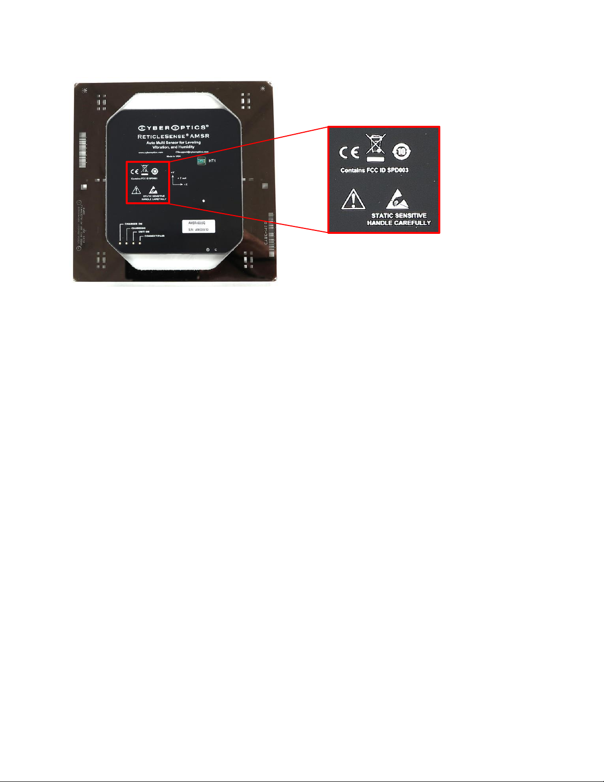
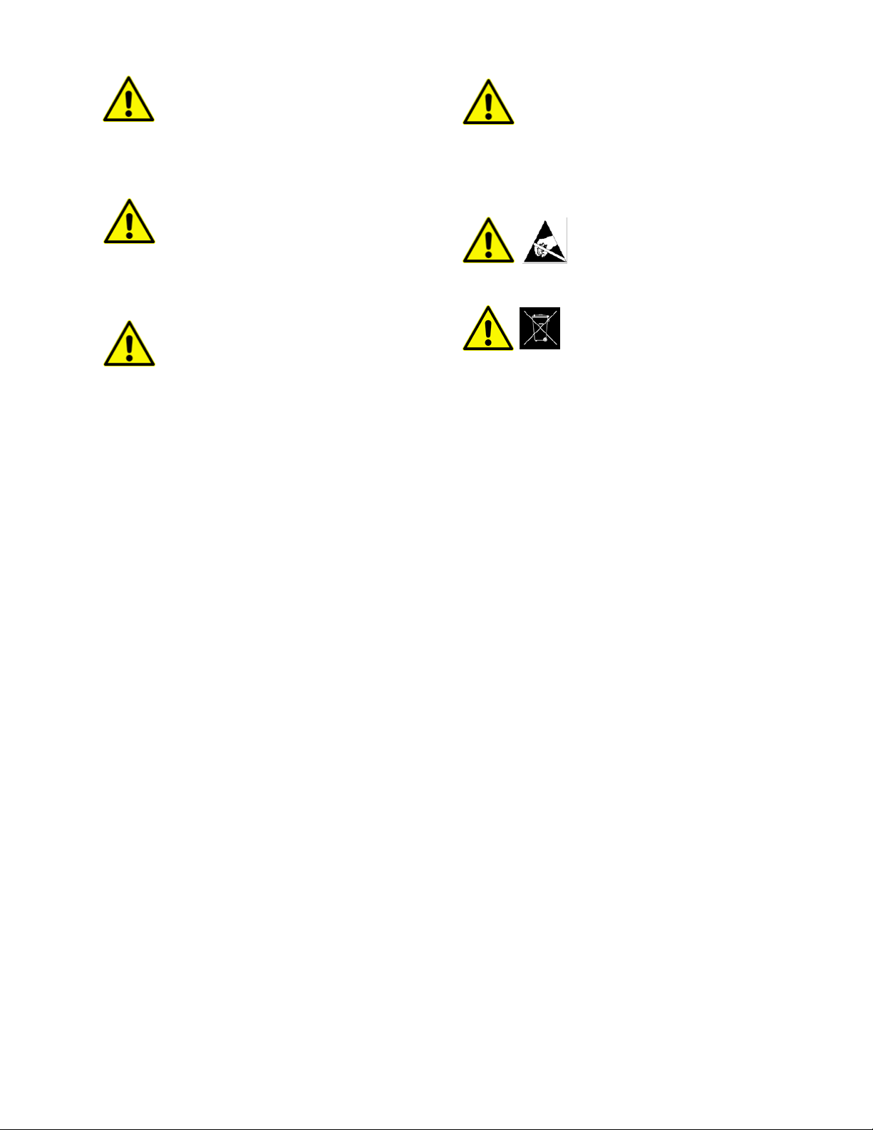
Labels on Devices
Hazard labels as they appear on the AMS devices.
WaferSense and ReticleSense Technical Support
Technical support is available from CyberOptics Corporation.
E-mail: CSsupport@cyberoptics.com
Phone: 763-542-5000
800-366-9131 (US and Canada only)
WaferSense and ReticleSense are registered trademarks, and ParticleView, and ParticleReview are trademarks, of
CyberOptics Corporation.
Third-party brands and names are the property of their respective owners.
Copyright © 2017 CyberOptics Corporation. All rights reserved.
5900 Golden Hills Drive, Minneapolis, Minnesota, 55416

9
Introduction
The CyberOptics WaferSense® and ReticleSense® Auto Multi-Sensors measure leveling, vibration and humidity
inside semiconductor process equipment. The family of products includes versions for 300mm (AMS-300C),
200mm (AM-200C), 150mm (AMS-150C) and 6 inch reticles (AMSR).
The MultiView™ software application makes it easy to see results in real- time. The large display and wireless link
let you place the computer at a convenient distance from the AMS device.
The AMS consists of the following components:
• AMS hardware. The AMS is designed with a wafer-like or reticle-like form factor, so it can fit in most
handling equipment or tools. The device is also vacuum compatible.
• MultiView and MultiReview™ software. The MultiView software application monitors the vibration,
humidity, and leveling measurements and other status information in real time. MultiReview lets you play
back log files recorded in MultiView. Both applications run on most personal computers that use the
Microsoft Windows operating system. See “Specifications” on page 127 for platform requirements.
• Wireless link. The software communicates with the AMS by using a Bluetooth wireless link that attaches
to a USB port on a personal computer.
• Charging case. The AMS is powered by an internal rechargeable battery, which you recharge by placing
the AMS into the charging case.
• Carrying case. The carrying case makes it easy to take your complete AMS system with you in the plant or
on the road.
The following section provides you with instructions for installing your AMS system.
Introduction

10
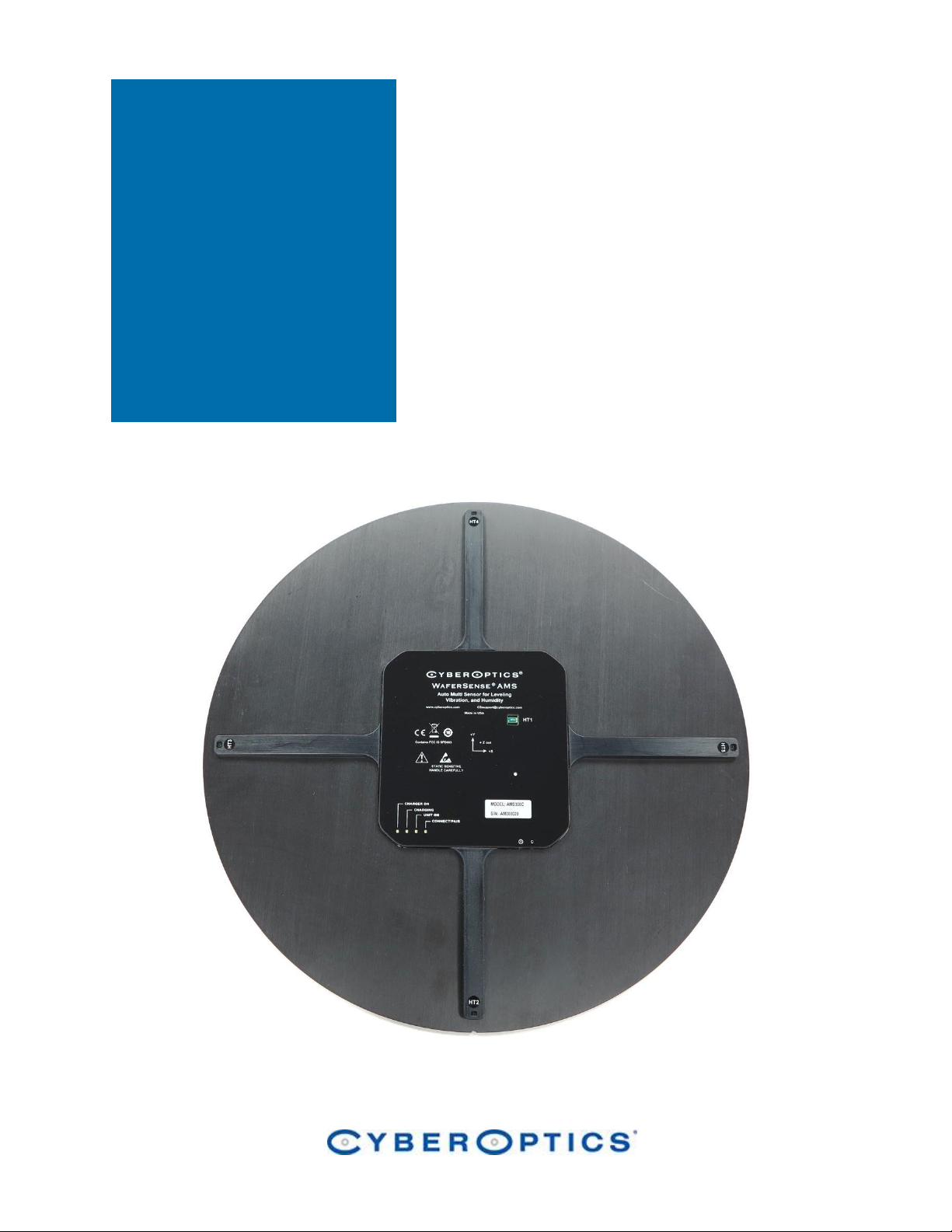
The AMS controls and LED indicators are visible on the outside of the device as shown below.
Figure 1. Controls and LED Indicators
LED indicators
Reset switches are
located on the edge of
the unit

11
Installing Your AMS
This section describes the procedures you need to perform to install your AMS system and get it ready for use. For
best results, perform the procedures in the order they are presented in this chapter:
• Installing the AMS software
• Installing the wireless link on the USB port
• Checking communications between the link and the AMS
• Registering your AMS
• Running the MultiView application
Installing
your AMS
Caution
Dropping the AMS or hitting it against a hard object can bend, break, or chip the housing; damage the internal
components; or knock the AMS out of calibration. While it is not as fragile as an actual silicon wafer, handle the
AMS with care, as you would any precision instrument. If the AMS is damaged or in need of calibration, see the
“Maintaining Your AMS” section.
Caution
The AMS is thicker than a standard silicon wafer so use extreme care to assure that the wafer has proper
clearances when being transported through the tool. For example, when you use the device in a tool for the
first time, move the AMS through the tool in manual mode, visually verifying all clearances. Even when
clearances are sufficient for safe AMS pass-through, if the robot end-effector is taught too high, you risk
crashing and damaging the AMS.
Do not direct compressed air or gas into the humidity sensors on the AMS. Damage to the unit may result.
12
Installing the AMS Software
To install and run the AMS software MultiView and MultiReview, your computer must have the following:
• Windows XP, or Windows Vista and Windows 7 (32-bit or 64-bit), Windows 8, Windows 10 operating
systems
• One free high-power USB 1.1 or USB 2.0 port
To install the AMS software, do not plug in the link before you start. The software must be installed first using the
following steps:
1) Log on using an account with Administrator privileges.
2) Insert the AMS Installation Disk into the CD drive.
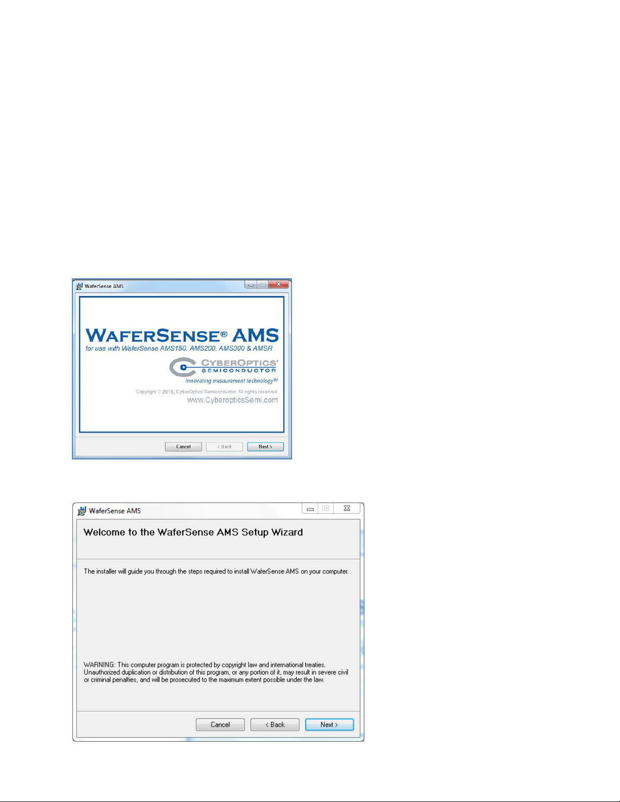
The Setup Wizard starts automatically, as shown in the figure below. If the wizard doesn’t start automatically,
use Windows Explorer to view the contents of the CD and double-click the setup.exe program.
3) Click Next and the Welcome screen of the Setup Wizard appears.
13
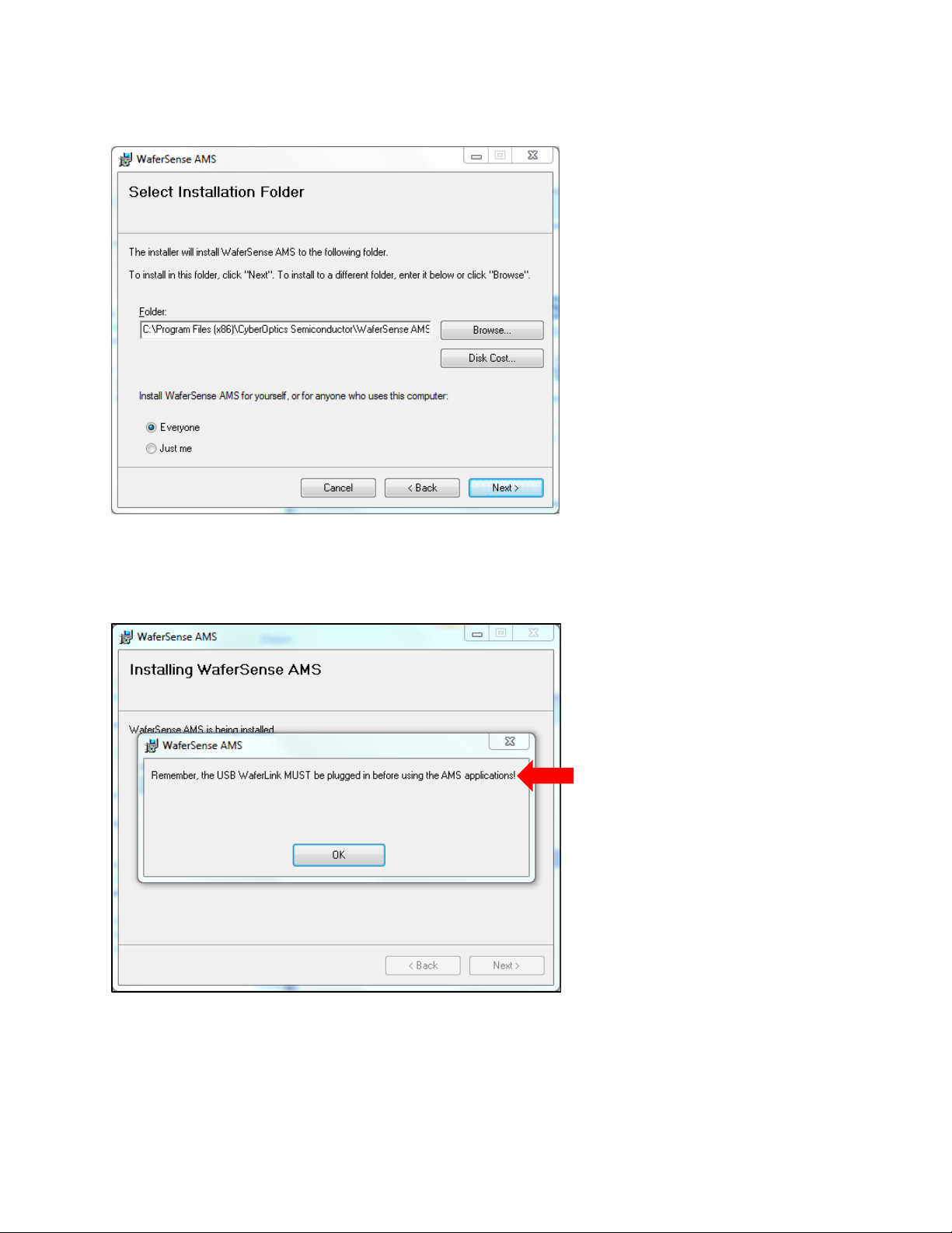
4) Click Next and License Agreement screen appears. Click the I agree button. Click the Next button and the
Select Installation Folder screen appears. Either accept the default settings, or enter a different path and
access settings.
5) Click the Next button and Confirm Installation screen appears. Click the Next button, and the Setup Wizard
starts installing the WaferSense AMS operating software on your computer. A blue progress bar appears and,
when the installation is complete, the following screen appears.
6) Click OK. The WaferSense AMS software is now installed. This is important! Do not run the AMS software at
this time. If you do, you will compromise the overall AMS installation procedure, and get an error message
saying ftd2xx.dll not found.
7) The next step is to install the wireless link (as described in the next section).

14
Installing the Wireless Link
Before starting the wireless link installation, complete “Installing the AMS Software” on page 12. To install the
wireless link:
1) Turn on your computer.
2) Locate an unused, high-power USB port on your computer. The AMS wireless link module requires a high-
power USB port, such as the built-in ports on your computer and ports on USB hubs that have power cords.
Unpowered USB hubs won’t work.
3) The USB cable provided with your AMS system has a different plug on each end. Locate the end with the plug
that matches the USB port on your computer and plug the cable into the port.
4) Plug the other end of the cable into the link module.
5) Windows automatically finds the drivers installed during the Link Device Installer—see the figures on the
previous page.
6) The Power light on the module turns on indicating that the module is getting power from the USB port. Ignore
the Pair Status and Connection Status lights for now.

15
Checking the Communications Between the Link and the AMS
To complete the installation, verify that the AMS and link can communicate:
1) The AMS operates from an internal rechargeable battery. Before using the AMS for the first time, charge it for
two hours. For information on checking the charge on the battery and the procedure for recharging, see
“Using the Rechargeable Battery” on page 28.
2) On the AMS, there are reset switches as described in the “Introduction” section on page 9. These switches are
recessed and are rarely used, and require the use of a paper clip, or small device to activate. Placing the unit in
the charging case and connecting the charger power supply will start the AMS, see “Opening and Closing the
Charging Case” on page 22.
3) Verify that the Pair Status lights on both the AMS and link module are on. The AMS and link module in your kit
were paired at the factory and will operate with only that particular link module. If either light is not on, your
AMS and link might not be paired with each other. To reset the pairing, see “Changing the Pairing between the
AMS and Link” on page 31.
4) Immediately after turning on the AMS, the Connection Status lights on the AMS and link will blink slowly.
After a few seconds the AMS and link will connect and both lights will be on and no longer blinking. If the
lights continue to blink, see “Monitoring the Wireless Connection to the AMS Device” on page 30.
5) After starting the MultiView application (see “Running the MultiView Application” on page 17), you can verify
the connection to the AMS by comparing the serial number printed on the AMS to the serial number shown in
the About dialog, which is available in the MultiView application by choosing the Help > About menu item. If
the MultiView application is not running, the AMS turns off automatically after 30 minutes.
That completes the installation of your AMS system.

16
Registering Your AMS for Calibration Service
To maintain optimum performance, every twelve months you should have your AMS calibrated and the battery
replaced. These services can be performed only at the factory.
To help you keep track of the next service date so you can schedule this service when it is convenient, register your
AMS with the factory. When you start the MultiView application (see “Running the MultiView Application” on
page 17), it prompts you to register your AMS for calibration. You can also register your AMS in any of the
following ways:
• On the Internet: http://cyberoptics.com/semiconductor_categories/wsregistration.html
• By sending an e-mail message containing the model, serial number, and contact information to
wsregister@cyberoptics.com
17
Running the MultiView Application
To start the MultiView application:
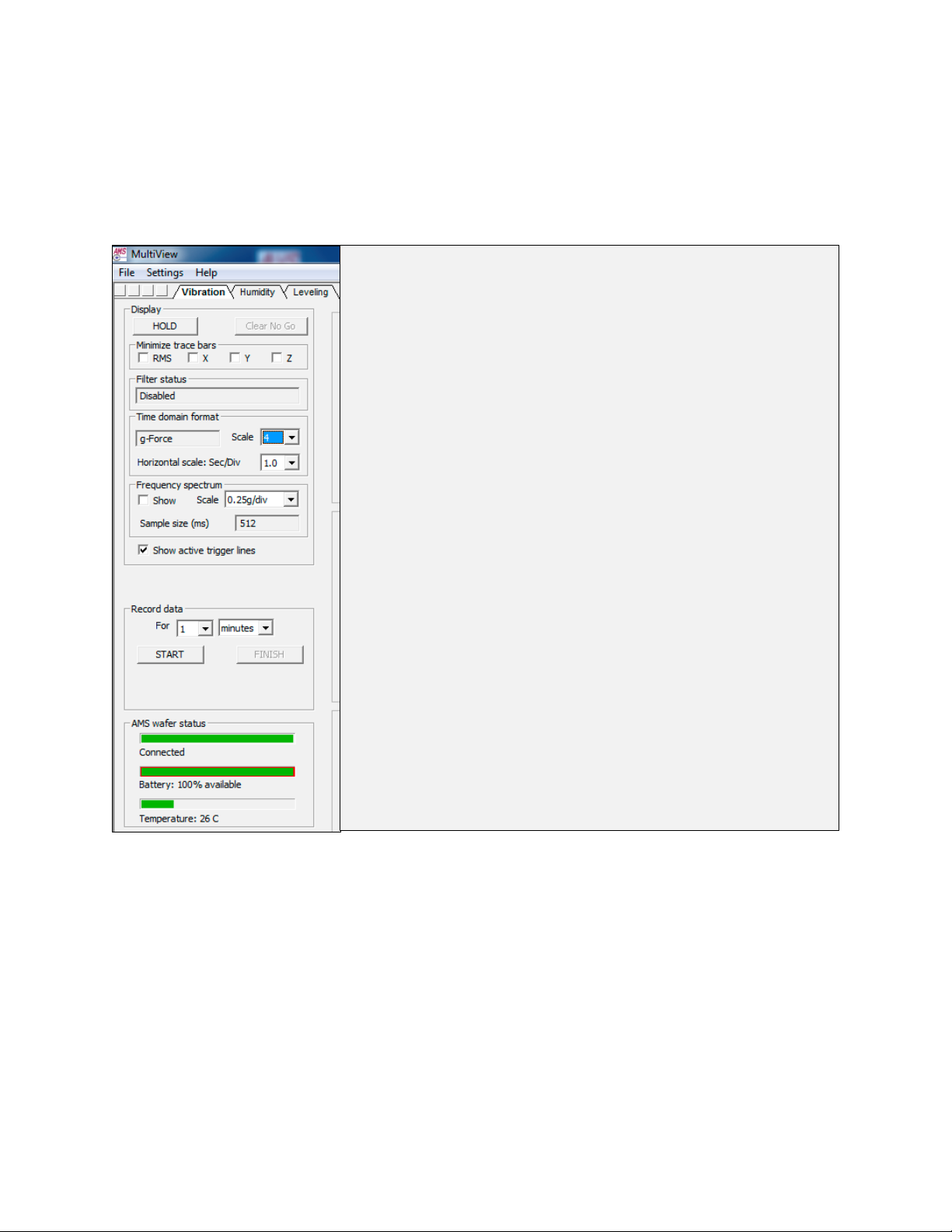
1) From the Windows Start > Programs menu, choose WaferSense AMS > MultiView.exe. The MultiView
application starts, as shown in the figure below. Initializing communications usually takes less than a second. If
the AMS has not been registered, MultiView will display the Calibration Registration dialog. To complete the
registration, proceed to the next step.
Graphing section of the screen
18
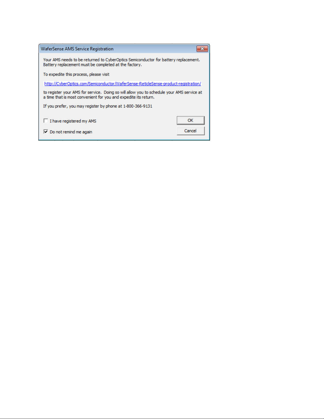
2) If MultiView displays the AMS Calibration Registration dialog, as shown in the figure below, you haven’t
registered your AMS. Follow the instructions in the dialog to complete the registration.
19
Technical Support
CyberOptics offers free technical support to customers. If the AMS hardware or software appear to be
malfunctioning, please contact us, and we’ll be happy to assist you.
When you contact us, please make sure that you have the following information available:
• A detailed description of the problem you are having, including the exact text of any error messages and a
list of steps to reproduce the problem.
• Information about your computer, including manufacturer, CPU type, version of Windows, and memory
size.
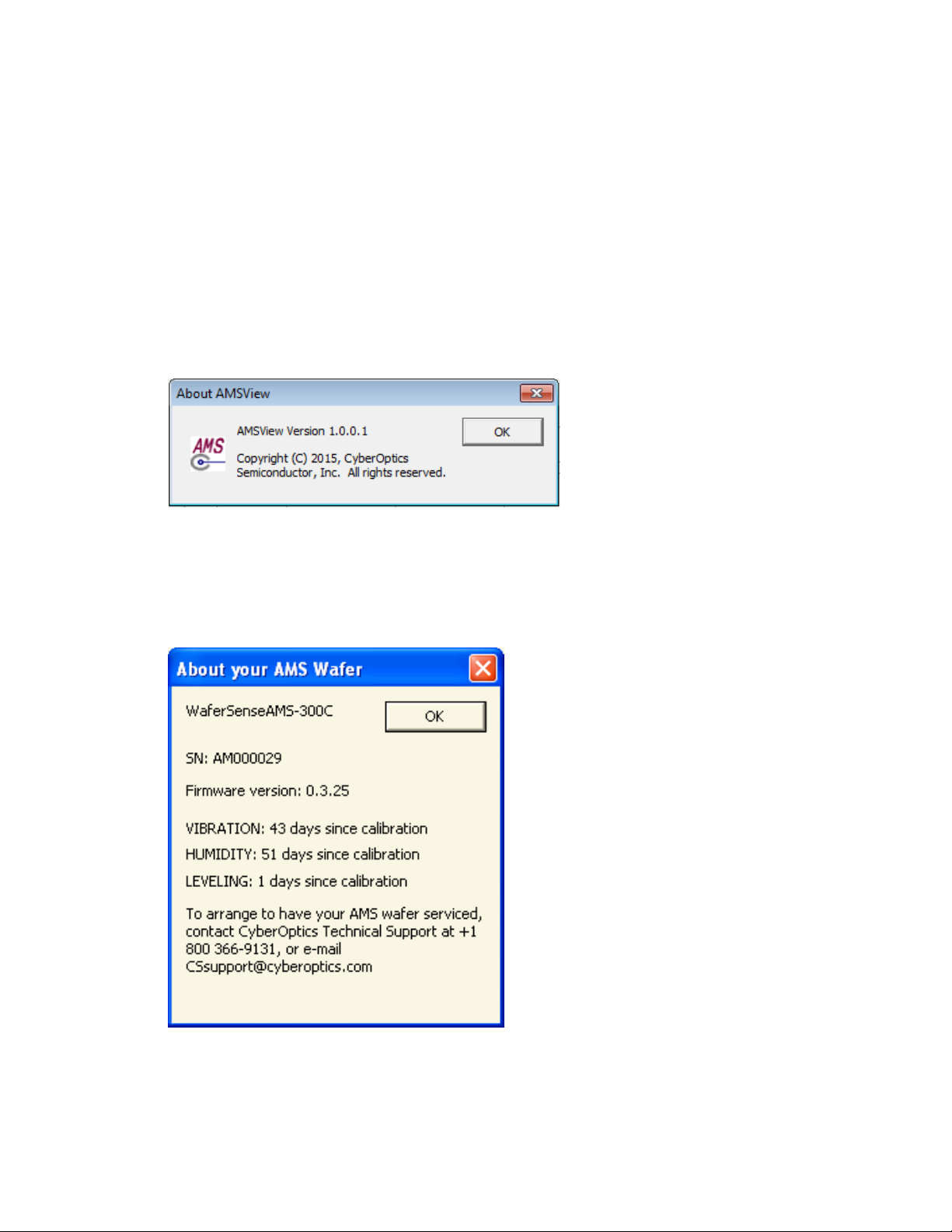
• The version of the MultiView application. The software version is available in the MultiView application by
choosing the Help > About AMSView menu item.
• If you are using MultiReview, a similar dialog is available from the Help > About MultiReview menu item.
• The serial number of your AMS. The serial number of the AMS is printed on a label on the top of the AMS.
In addition, the serial number is also available in the MultiView application by choosing the Help > About
menu item.

20
Technical support:
• Toll free: 800-366-9131 (US and Canada only)
• E-mail: CSsupport@cyberoptics.com
• Internet: www.Cyberoptics.com

21
Using Your AMS
This section gives you instructions for performing the following tasks with the AMS device:
• Open and closing the charging case
• Use the AMS controls
• Use the AMS indicators
• Use the Vibration, Humidity, and Leveling tabs
• Change colors in the trace screen
• Print the MultiView window
• Monitor the operating temperature of the AMS
• Use the rechargeable battery
• Monitor the wireless connection to the AMS device
• Change the pairing between the AMS device and link
Using Your AMS
22
Opening and Closing the Charging Case
The AMS device comes in a plastic charging case that is used for storing it when not in use and for charging the
rechargeable battery in the AMS (see “Using the Rechargeable Battery” on page 28). The AMS device should be
stored in the sealed charging case when not in use.
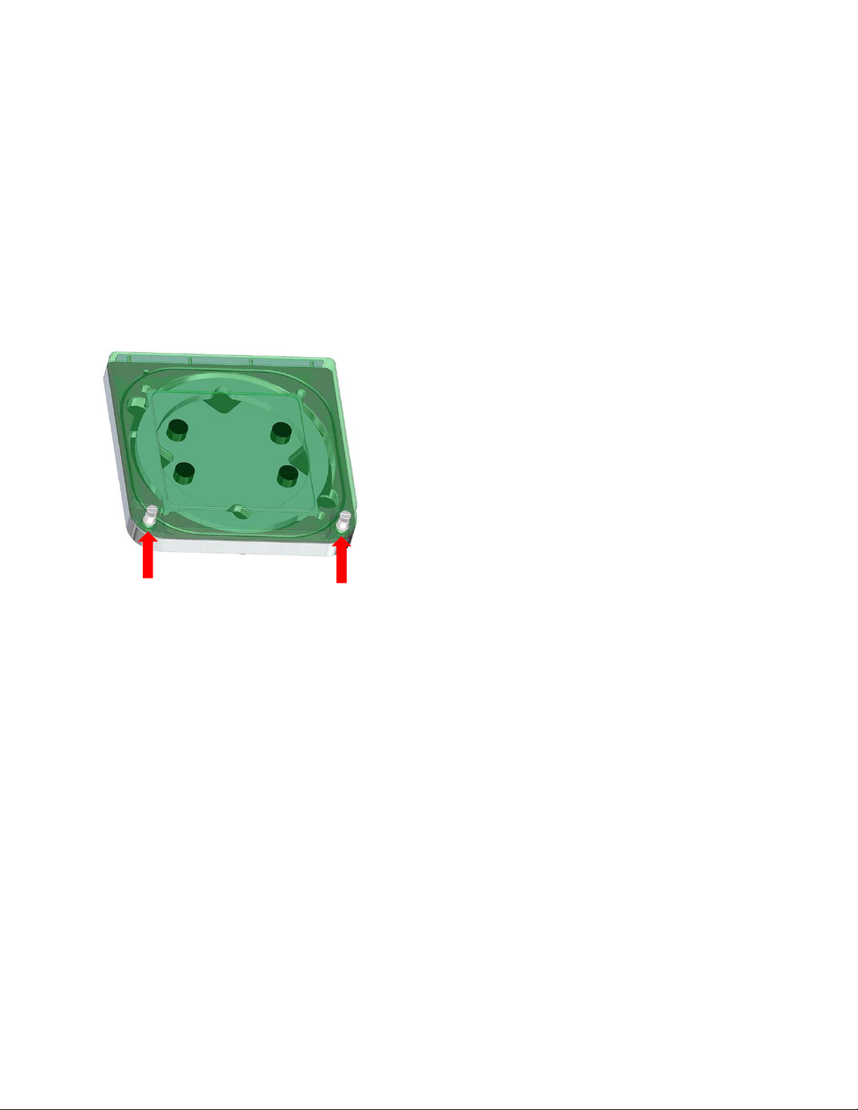
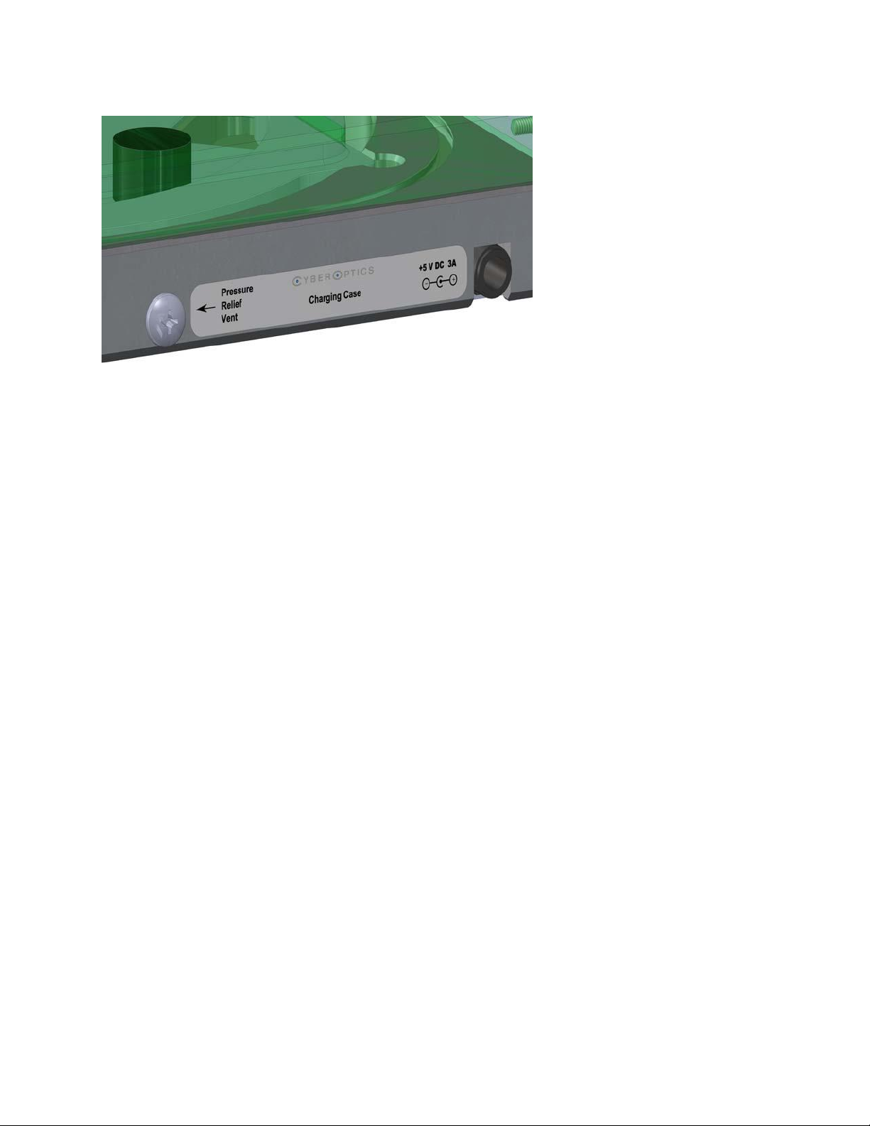
The charging case is air-tight. After air transport it may be necessary to relieve the pressure differential in order to
open the case. To do so, loosen the pressure relief vent screen until air enters the case. Then re-tighten the screw.
Opening the Charging Case
To open the charging case:
1) Loosen the captive screws on the top of the case.
2) Lift the lid of the charging case using the captive screws.
Closing the Charging Case
To close the charging case:
1) Lower the lid.
2) Tighten the captive screws until the top of the case is secured.
Loosen the captive screws

23
Using the AMS Controls
AMS devices are designed to operate “hands free” in normal use.
• The unit is turned on by inserting the unit in the charging case and applying power to the charging case.
• The unit is completely turned off by activating the “shutdown” button in the MultiView software.
• A “shutdown” turns off all internal electronics in the AMS. After a shutdown the unit must be restarted in
the charging case. Therefore, if the intent is to put the unit into standby mode where the electronics are
still active, the “stop” button in MultiView should be used instead of the “shutdown” button.
• In abnormal situations, the reset switches on the front panel can be used to activate a shutdown or to
turn the unit on from a shutdown. See “Controls and LED Indicators” on page 10 for a view of the reset
switches. The switch indicated by a combined “1” and “0” symbol turns the unit both on and off.
Using the AMS Indicators
The AMS has the following status LEDs (see “Controls and LED Indicators” on page 10).
• Charger On. Glows green, when power is applied to the charging case.
• Charging. Glows red, when the unit is being charged. Goes dark when the battery has reached 100%
charge. Glows red, if the charger is connected and the battery discharges below 95%. Goes dark when the
inductive charger is no longer powered.
• Unit On. Indicates when the device is on.
• Connect/Pair. Note: Glows green, when the unit is successfully paired with a link box. Blinks red/green
slowly, when it is searching for a link. This usually occurs just after turn on or before the link box is
powered by the host computer. Blinks red/ green rapidly, when the pairing function is activated by the
“C” reset switch. This rapid blinking indicates it is receptive to a new pairing.
• When the AMS is on and has been removed from its charger and is ready for in-tool use, the “Unit on”
and the “Connect/Pair” LEDs should both be glowing steady green. The AMS does not necessarily need to
be removed from its charger to be used, nor does it need to be used in-tool.
24
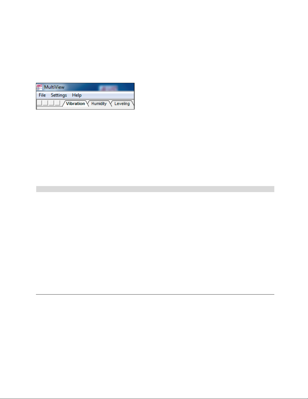
Using the Vibration, Humidity, and Leveling Tabs
The MultiView opening screen contains three tabs, which allow you to access the following AMS functions.
• Vibration
• Humidity
• Leveling
Click on the appropriate tab, and the opening screen for that particular function is displayed.
Changing Colors in the Trace Screen
You can change the colors used to display traces and other elements of the display. The table below shows the
display elements that you can change.
Display Element
Description
RMS
RMS trace
X
X trace
Y
Y trace
Z
Z trace
Indicator
Vertical line at the right edge of the trace display, where new data is first displayed
Go/No-Go lines
Horizontal lines showing current active Go/No-Go tolerances
Trigger lines
Horizontal lines showing current active trigger settings
Grid lines
Horizontal and vertical section lines
Text
Labels on axes and for annotation
Background
Background color of the trace
25
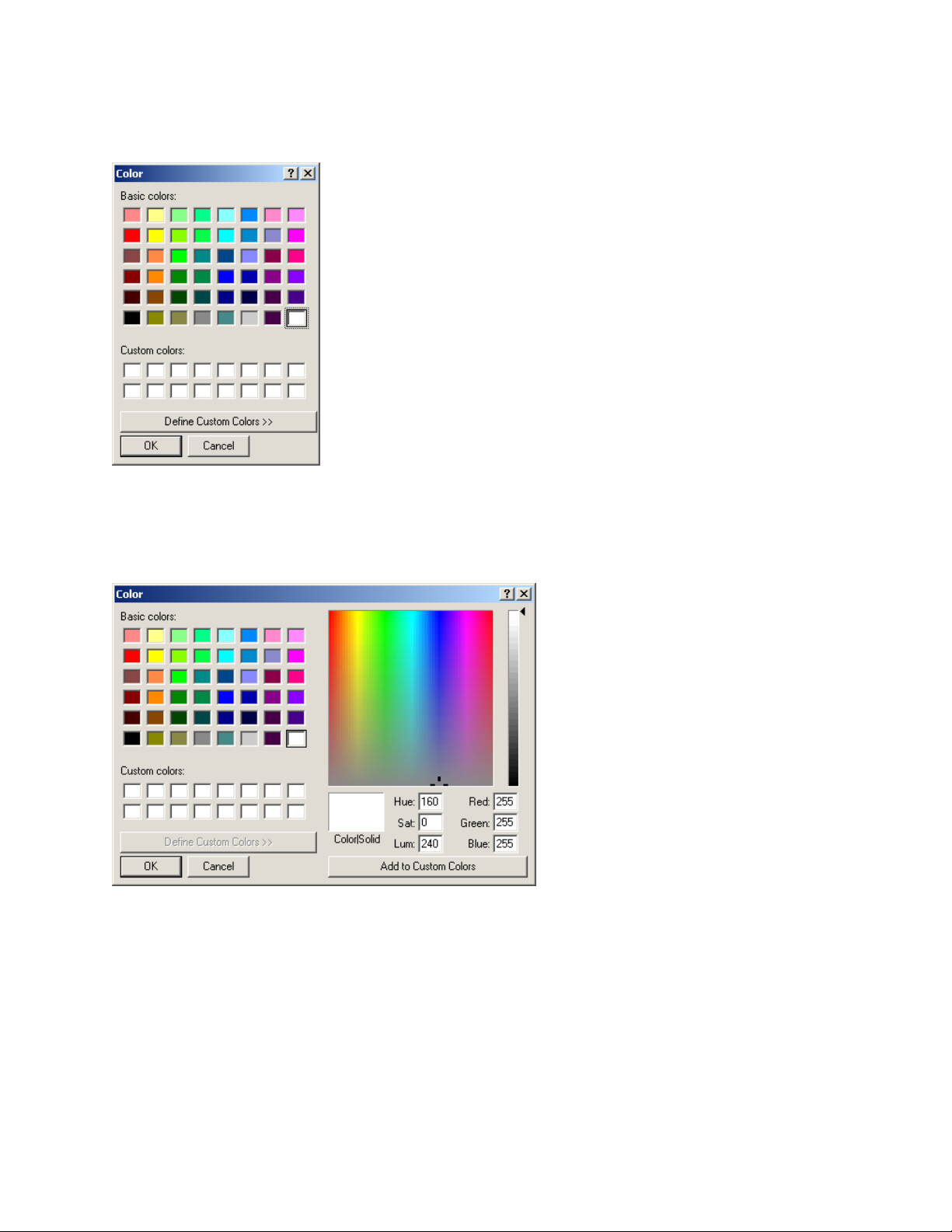
To change colors of the display elements, do the following.
1) From the Settings > Select Colors menu item, choose the display element you want to change. The color
palette is displayed.
2) If you want to use one of the existing color definitions, skip to the next step. If you want to define a custom
color, click Define Custom Colors. The color palette expands, as shown below. Specify the color as a
combination of hue, saturation, and luminosity, or as a combination of red, green, and blue, and click Add to
Custom Colors.
3) Click on the color you want to use for the display element and click OK.
4) To reset all colors to the default values, go to the Settings > Select Colors menu and choose Restore Defaults
to All.
5) To reset only the background color to the default value, go to the Settings > Select Colors menu, and choose
Restore Default Background.

26
Printing the MultiView Window
You can print an image of the MultiView window to have a graphical record of the session. To print an image of the
MultiView window, do the following.
1) Choose File > Print.
2) In the Print dialog, click OK.
3) You can also select a printer other than the default and change the printer setup, or see a preview of what
MultiView will print.
• To select a different printer, change the paper selection or print orientation, or set printer properties,
choose the File > Print Setup menu item.
• To see a preview of what MultiView will print, choose the File > Print Preview menu item.
27
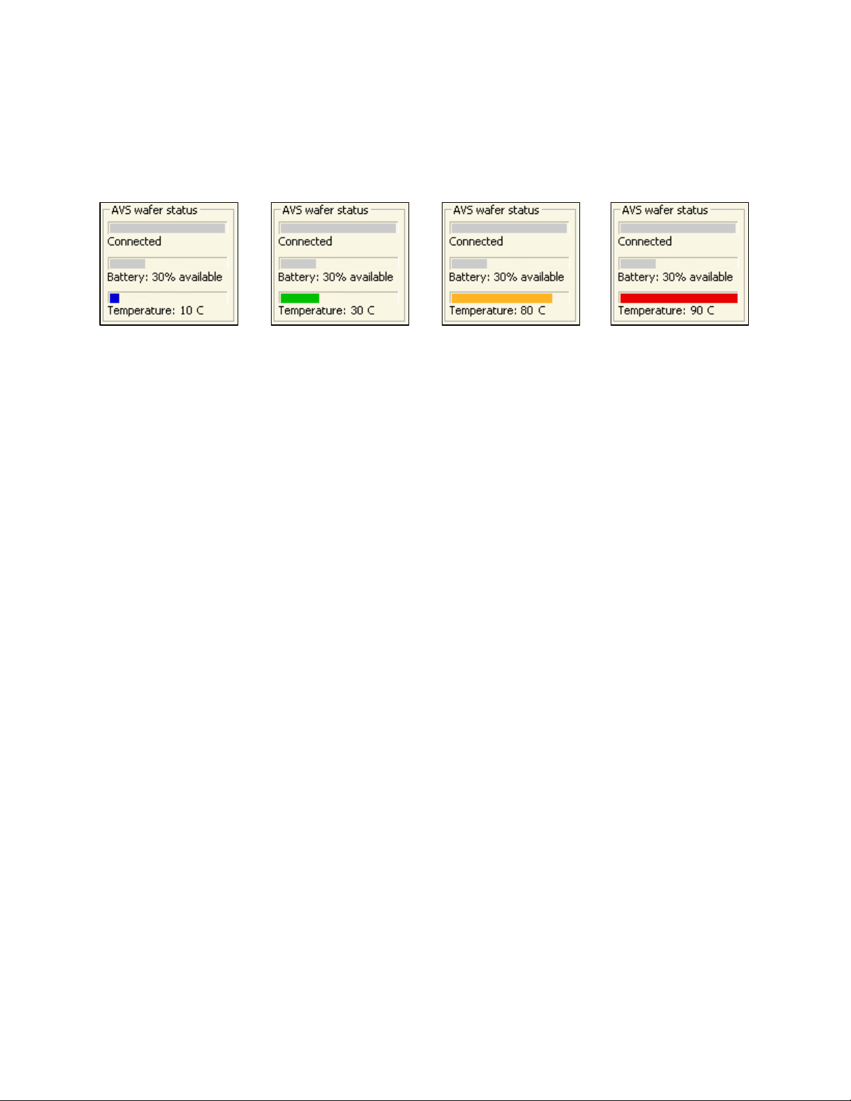
Monitoring the Operating Temperature of the AMS
The operating range for the AMS is 20–70 °C. The AMS can withstand exposure to higher temperatures for very
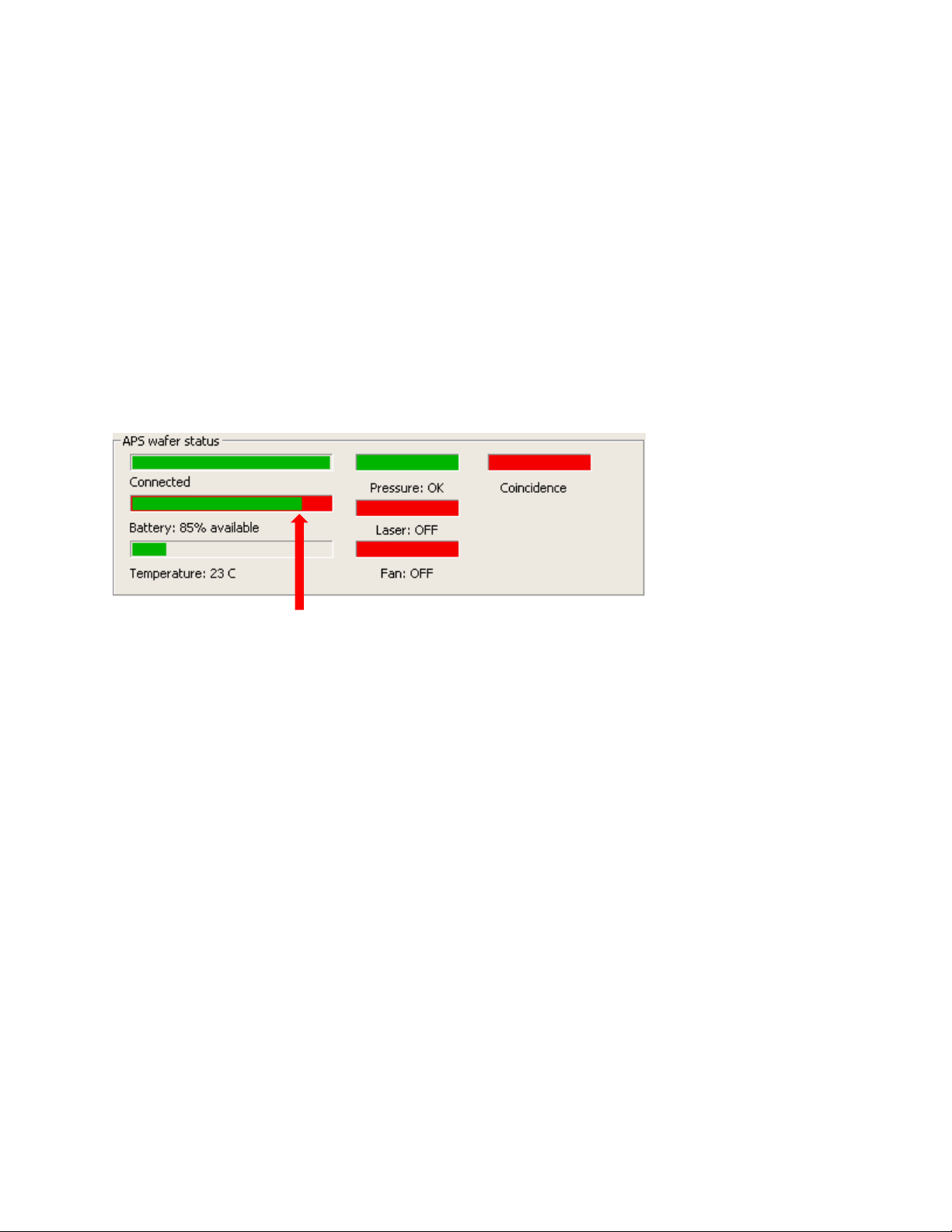
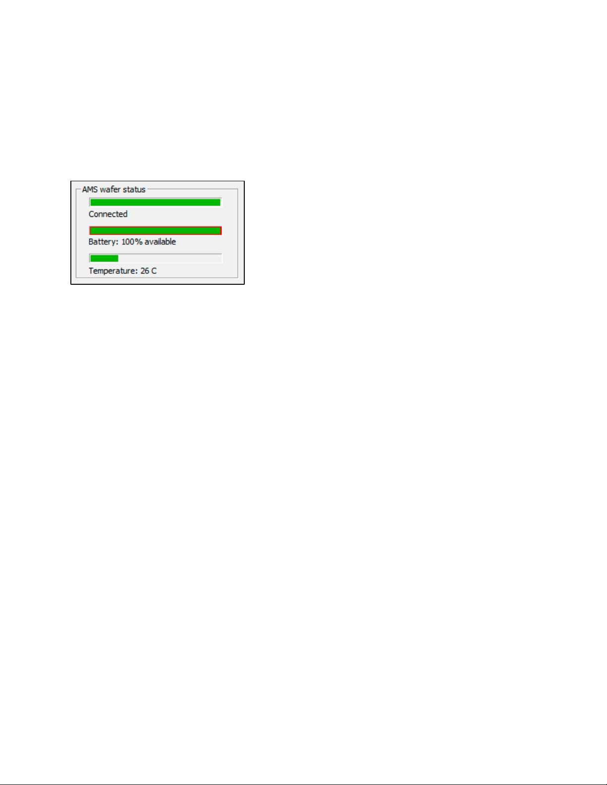
brief periods, if not in direct contact with a heating element. The Temperature monitor in the AMS wafer status of
the MultiView window shows the current operating temperature of the AMS using a numeric readout and a bar
graphic (as shown below).
Low Optimum Warning Danger
<20 °C 20–70 °C 71–80 °C > 80 °C
The temperature bar changes color to indicate where the current temperature is relative to the accurate operating
range, using the following color-coded bars.
• Blue
Less than 20 °C. The AMS is operating below the range, where it produces accurate readings.
• Green
20–70 °C. The AMS is operating in its optimum temperature range, where it produces readings meeting the
specified accuracy.
• Orange
71–80 °C. The AMS is operating above the range, where it produces the most accurate readings, but not so hot
that the AMS will be damaged.
• Red
Greater than 80 °C. The AMS is operating at a temperature so high that it might be damaged.
28
Using the Rechargeable Battery
The AMS operates from an internal rechargeable battery. From a full charge, the battery provides about four hours
of continuous use. Before using your AMS device for the first time, charge it for two hours.
The battery can be recharged about 400 times before the charge life starts to degrade significantly. The battery is
not user replaceable. For information on replacing the battery, see “Annual Factory Calibration and Battery
Replacement” on page 125.
Battery performance degrades at temperatures outside the temperature range: 15–45 °C.
Monitoring the Battery Level
MultiView receives frequent updates from the AMS on the status of the AMS’s battery. The Battery indicator in
the AMS status area of the MultiView window shows the approximate percentage of operating time remaining
before you must charge the battery.
Charging the Battery
To charge the AMS device’s battery:
1) Use only the battery charger supplied with your AMS device. Using a different battery charger might damage
your AMS or create a safety hazard.
2) Do not charge the AMS, if the temperature is higher than 45°C. Charging the AMS device at a temperature
higher than 45 °C might damage the AMS housing or create a safety hazard.
Battery status—connected and at 85% of full charge
29
3) Place the AMS device in the charging case (see “Opening and Closing the Charging Case” on page 22). Close
the lid.
4) Plug the charger line adapter into a 100 VAC to 240 VAC mains, and plug the other end into the charging case
connection on the right side of the charging case.
The charging case is air-tight. After air transport it may be necessary to relieve the pressure differential in
order to open the case. To do so, loosen the Pressure Relief Vent screw until air enters the case. Then retighten the screw.
5) When power is applied to the charging case, the Charger on LED will light and the Charging LED will also light,
unless the unit is already fully charged. In addition, the Unit on LED will light. If the unit is still paired to a
powered link box, the Connect/ Pair LED will light.
6) Charge the unit until the Charging LED goes dark. The unit is now fully charged and ready for data collection.
However, the unit can be used if not fully charged.
7) The AMS can remain in the charging case with power applied to the case even when fully charged. The battery
will not be damaged. The AMS should be stored in the sealed charging case when not in use.
30
Monitoring the Wireless Connection to the AMS Device
The MultiView application communicates with the AMS device by using a Bluetooth wireless link. The wireless link
has a range of up to 30 ft (10 m).
The Connection indicator in the AMS wafer status area of the MultiView window shows the quality of the wireless
connection between the AMS and the link module. The connection quality is indicated by the color of the bar and
the wording below the bar.
• Green—Connected. The connection between the link and AMS is good. With a good connection, the AMS
device is sending the maximum number of readings per second to the link module (at least 200 readings per
second).
• Yellow—Poor connection. There is some interference or other problem with the signal that is preventing the
link and AMS device from communicating at their maximum rate. When the indicator is yellow, the readings
are still accurate but aren’t being updated as frequently.
• Red—No connection. Indicates that there is no connection between the AMS device and link module. The
values in the display do not update when the indicator is red.
The Bluetooth wireless link technology used in the AMS is a low-power technology that operates in the 2.4 GHz
radio frequency band. This unlicensed band is also used by many other types of devices, such as cordless phones
and microwave ovens. Another 2.4 GHz device operating in close proximity could interfere with the AMS system.
When this happens, separating the devices by at least 6 ft (2 m) usually solves the problem.
Other factors can also affect the wireless link, such as the distance between the AMS device and link, and obstacles
between the device and link that block the signal. If MultiView indicates that the connection isn’t good, try moving
the wireless link module a few feet closer to the AMS device.
After turning off the AMS, the Connection indicator might not change to red for a few seconds.
 Loading...