

Physician’s Manual
VNS Therapy® Programming System
For Healthcare Professionals
May 2017
Note: This manual contains
information on the use of the
VNS Therapy programming
software programming
system. Physicians should
refer to the VNS Therapy Pulse
Generator physician’s
manuals for additional
important prescribing and
safety information.
1 of 58 — 26-0009-7500/0 (OUS)

Physician’s Manual — VNS Therapy Programming System
© Copyright 2017 LivaNova, Inc., Houston, Texas
All rights reserved.
2 of 58 — 26-0009-7500/0 (OUS)

1. DESCRIPTION AND USE 8
1.1. General Description 8
1.1.1. Intended Use 8
1.2. System Communication 8
1.2.1. Programmer Communications 8
1.2.2. Wand Communications 8
1.2.3. Communication Distance 9
1.2.3.1. Wand and Programmer 9
1.2.3.2. Wand and Generator 9
2. PRECAUTIONS 10
3. G
ET STARTED 11
3.1. Parts Included 11
3.2. Prepare System for Use 11
3.3. Basic Operation 11
3.3.1. Charge the Programmer 11
3.3.2. Turn Programmer ON/OFF 12
3.3.3. Turn the Programmer Screen ON/OFF 12
3.3.4. Check Programmer Battery 13
3.3.5. Set the Programmer Date and Time 13
3.3.6. Turn on Wand/Check Wand Battery 13
3.4. Connect Wand/Programmer 15
3.4.1. Preferred Wireless Wand Setup 15
3.4.2. Wired Wand Setup 15
Physician’s Manual — VNS Therapy Programming System
4. INTERROGATING THE GENERATOR 16
4.1. Interrogate (No Preferred Wand) 16
4.2. Interrogate (With Preferred Wand) 18
4.3. Interrogate (Change Preferred Wand) 19
5. HOW TO USE THE SOFTWARE 20
5.1. Summary Screen 20
5.2. Quick Access Bar 21
6. PROGRAM THE DEVICE 23
6.1. Edit Patient Data 23
6.2. How to Adjust Parameter Settings 23
6.3. How to Configure Seizure Detection Settings 25
6.3.1. Turning the Detection Feature ON/OFF 25
6.3.2. Set Heartbeat Detection 26
6.3.3. Use Verify Heartbeat Detection 26
6.3.3.1. Visual Indicators During Verify Heartbeat Detection 27
6.3.4. Set the AutoStim Threshold 27
6.3.5. Stimulation Settings on the AutoStim Tab 28
6.3.5.1. Detection and Time Restraints 28
6.4. Potential Error Conditions Related to Programming 28
6.4.1. Partial Programming (Model 102R) 28
6.4.2. Partial Programming Interruption (Models 103-106 and 1000) 28
6.4.3. Cross-programming (Model 102 Generators ONLY) 29
3 of 58 — 26-0009-7500/0 (OUS)

Physician’s Manual — VNS Therapy Programming System
7. GUIDED PROGRAMMING 30
8. S
CHEDULED PROGRAMMING 31
9. D
AY/NIGHT PROGRAMMING 32
10.D
EVICE DIAGNOSTICS 33
10.1. Reading Test Results 33
10.2. System Diagnostics 36
10.3. Normal Mode Diagnostics (Model 102) 36
10.4. Magnet Mode Diagnostics 36
10.5. AutoStim Diagnostics (Model 106 and 1000) 37
10.6. Generator Diagnostics 37
10.7. Diagnostic Test Differences Between Models of Generators 37
10.8. Potential Error Conditions Observed in Diagnostics 38
11.HISTORY 39
12.E
VENTS AND TRENDS 40
13.M
14.P
15.T
ANAGING PROGRAMMER INFORMATION 41
ROGRAMMER SETTINGS 42
ROUBLESHOOTING 43
15.1. Non-responsive Programmer or Wand 43
15.2. Communication Issues 43
15.2.1. Wand Not Connecting to Programmer (Wireless) 43
15.2.2. Wand Not Connecting to Programmer (Backup Cable) 44
15.2.3. Wand Not Communicating with Generator 45
15.3. High/Low Lead Impedance and Low Output Current Issues 46
15.3.1. High Lead Impedance in the OR 46
15.3.2. Low Lead Impedance in OR 47
15.3.3. High Lead Impedance at Follow-up Visits (Model 102) 48
15.3.4. High/Low Lead Impedance or Low Output Current at Follow-up Visit (Models 103-106 and 1000)
49
15.4. Generator Battery Issues 50
15.4.1. Low Battery/End of Service Indications in OR 50
15.4.2. New Generator Disabled Due to EOS at First Interrogation 51
15.4.3. Sudden Decrease In Remaining Battery Power 52
15.5. Heartbeat Detection Issues 52
15.5.1. Heartbeat Detection Inaccurate (Over/Under) in OR or at Follow-up Visit 52
15.6. Seizure Detection Issues 53
15.6.1. Inaccurate AutoStims at Follow-up Visit for Generator Model 106 and 1000 53
16.GENERATOR RESET 55
17.MAINTENANCE, HANDLING, AND DISPOSAL 56
17.1. The Programmer 56
17.2. The Wand 56
17.3. Disposal 56
4 of 58 — 26-0009-7500/0 (OUS)

Physician’s Manual — VNS Therapy Programming System
18.PROGRAMMING SYSTEM SPECIFICATIONS AND GUIDANCE 57
18.1. Wand and Programmer Specification 57
18.2. Electromagnetic Emissions Guidance for Wand 57
19.CONTACT INFORMATION AND SUPPORT 59
List of Tables
Table 1 Diagnostic/Parameter Result Summary 34
Table 2 DC DC Code Conversion and Estimated Impedance Range 36
Table 3 Diagnostic Test Differences Between Models of Generators 37
Table 4 Programming System Specification 57
Table 5 Electromagnetic Emissions 57
Table 6 Electromagnetic Immunity 58
Table 7 Electromagnetic Immunity to Proximity Fields from RF Wireless Communications Equipment 58
List of Figures
Figure 1 System Parts 11
Figure 2 Connect the Charger 12
Figure 3 Power On Programmer 12
Figure 4 Adjust Programmer Time and Date 13
Figure 5 Power On Wand 14
Figure 6 Power Indicator (Battery OK) 14
Figure 7 Low Battery Indicator 14
Figure 8 Wand Battery Replacement 15
Figure 9 Main Screen 16
Figure 10 Wand Search Screen 17
Figure 11 Wand (SN) Selection Screen 17
Figure 12 Successful Wand Connection 18
Figure 13 Interrogate Generator Screen 18
Figure 14 Main Screen - Preferred Wand 19
Figure 15 Summary Screen 21
Figure 16 Quick Access Bar 22
Figure 17 Edit Patient ID Screen 23
Figure 18 Output Warning Screen 24
Figure 19 Confirmation Screen 25
Figure 20 Verify Heartbeat Detection Screen 26
Figure 21 Verify Heartbeat Detection - Test in Progress 27
Figure 22 Programming Failed Warning Screen 29
Figure 23 Accessing Diagnostics 33
Figure 24 Diagnostics Results Example 34
5 of 58 — 26-0009-7500/0 (OUS)

Physician’s Manual — VNS Therapy Programming System
Figure 25 Solution Steps for a Non-responsive Programmer or Wand 43
Figure 26 Solution Steps For Wand Not Connecting to Programmer (Wireless) 44
Figure 27 Solution Steps for Wand Not Connecting to Programmer (Backup Cable) 45
Figure 28 Solution Steps for Wand Not Communicating with Generator 46
Figure 29 Solution Steps for High Lead Impedance in OR 47
Figure 30 Solution Steps for Low Lead Impedance in OR 48
Figure 31 Solution Steps for High Lead Impedance at Follow-up Visits (Model 102) 49
Figure 32 Solution Steps for High/Low Lead Impedance or Low Output Current at Follow-up Visit (Models 103-
106 and 1000) 50
Figure 33 Solution Steps for Low Battery/End of Service Indications in OR 51
Figure 34 New Generator Disabled Due to EOS at First Interrogation 52
Figure 35 Solution Steps for Heartbeat Detection Inaccurate in OR or at Follow-up Visit 53
Figure 36 Solution Steps for Inaccurate Detection at Follow-up Visit (Model 106) 54
6 of 58 — 26-0009-7500/0 (OUS)

Physician’s Manual — VNS Therapy Programming System
1. DESCRIPTION AND USE
1.1. General Description
The LivaNova VNS Therapy ® Programmer, Model 3000 version 1.0, and Programming Wand (“Wand”),
Model 2000, allows you to interrogate and program the following VNS Therapy generators:
Model 102 Pulse
Model 102R Pulse Duo
Model 103 Demipulse
Model 104 Demipulse Duo
Model 105 ApsireHC
Model 106 AspireSR
Model 1000 SenTiva
Note: For a list of symbols and terms used with the LivaNova VNS Therapy Programming System, go
to www.VNSTherapy.com/???.
1.1.1. Intended Use
The VNS Therapy Programming System is intended for use only with VNS Therapy generators in a
professional healthcare facility environment, and is subject to the same indications for use.
1.2. System Communication
The VNS Therapy Programming System includes a computer pre-installed with VNS Therapy
programming software and a programming wand. The wand and the programmer connect wirelessly.
The system allows you to:
interrogate and adjust therapy parameters for the generator
assess generator and lead function
view device histories
export session reports
1.2.1. Programmer Communications
The programmer will indicate communication in the following ways:
Musical notes a successful interrogation, diagnostics, or applied changes
Screen messages for successful, failed, or suggested operation
1.2.2. Wand Communications
The wand indicator lights will illuminate when the:
wand is powered on (two green lights below power button)
wand is connected to the programmer (four green lights around the power button)
wand is communicating with the generator (white flashing generator icon)
wand battery is low (orange battery indicator)
7 of 58 — 26-0009-7500/0 (OUS)

Physician’s Manual — VNS Therapy Programming System
1.2.3. Communication Distance
1.2.3.1. Wand and Programmer
The wireless connection between the programmer and wand will operate up to 3 meters
(approximately 10 feet) under most conditions. If communication is unstable, use the supplied USB
cable to connect the wand and the programmer instead.
1.2.3.2. Wand and Generator
The communication distance between the wand and the generator should not be more than 1 inch.
8 of 58 — 26-0009-7500/0 (OUS)
Physician’s Manual — VNS Therapy Programming System
2. PRECAUTIONS
For optimal performance and safety, review the following:
Do not load other software onto the programmer. Doing so may interfere with the efficiency and function of
the pre-installed VNS Therapy Software.
The programmer is tested to the same level as typical consumer electronic devices. However, the equipment
is not rated for use in the patient environment (as defined by IEC 60601-1). Do not simultaneously touch the
patient and programmer while programming. Additionally, do not plug the programmer into AC power while
it is being used in a patient environment.
Warning: Do not connect unapproved equipment. Doing so can damage the system and/or cause
injury.
Warning: Do not modify the system unless directed to by LivaNova.
Warning: Use of accessories, transducers and cables other than those specified or provided by the
manufacturer of this equipment could result in increased electromagnetic emissions or decreased
electromagnetic immunity of this equipment and result in improper operation.
Warning: Use of this equipment adjacent to or stacked with other equipment should be avoided
because it could result in improper operation. If such use is necessary, this equipment and the other
equipment should be observed to verify that they are operating normally.
Warning: Portable RF communications equipment (including peripherals such as antenna cables and
external antennas) should be used no closer than 30 cm (12 inches) to any part of the Wand, including
cables specified by the manufacturer. Otherwise, degradation of the performance of this equipment
could result.
Warning: MR Unsafe devices include the programming wand, computer, and patient magnet. Theses
devices must not be brought into the MR scanner room.
Warning: Safeguard the VNS Therapy Programming System against theft. Theft could lead to
malicious activities against the System.
9 of 58 — 26-0009-7500/0 (OUS)
Physician’s Manual — VNS Therapy Programming System
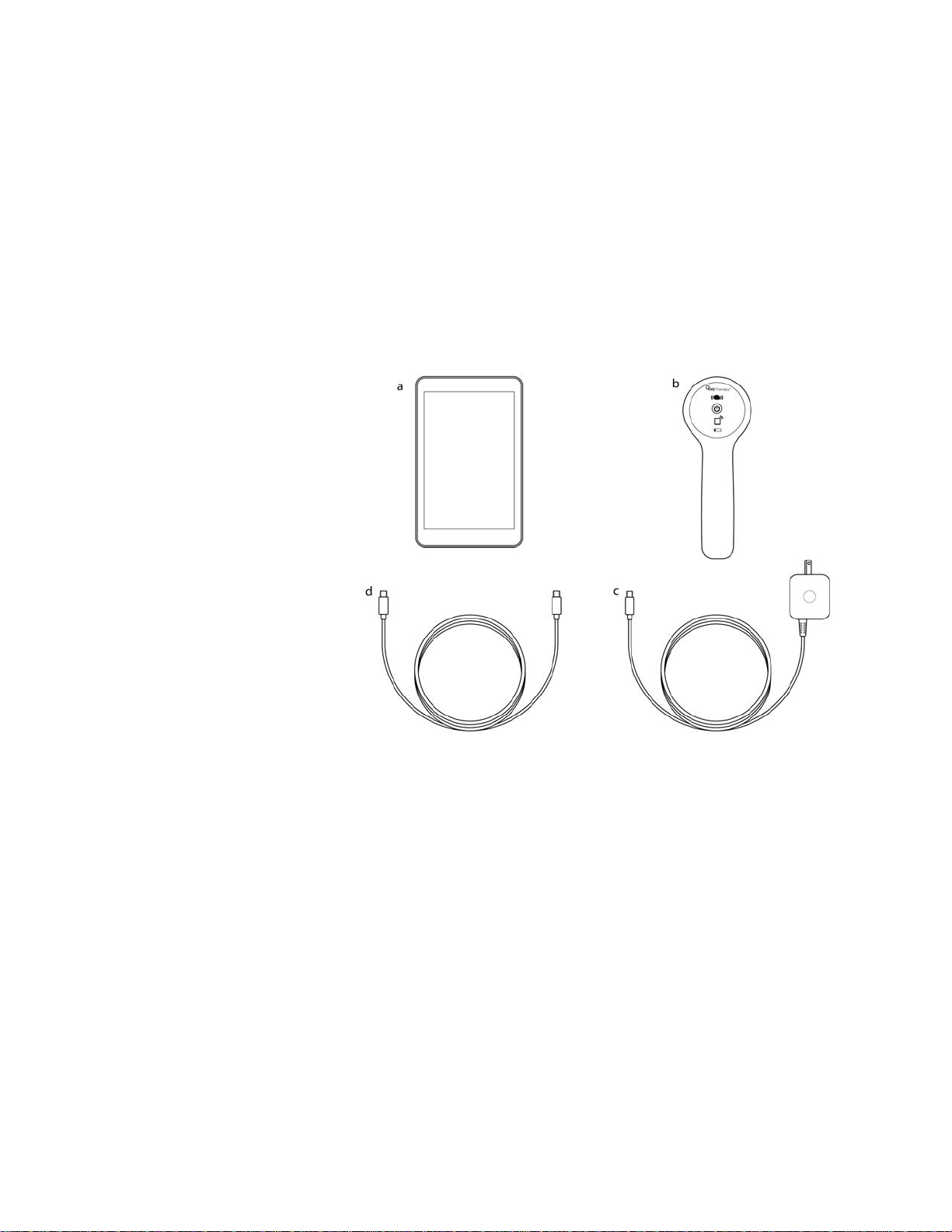
a. Programmer
b. AC Power Adapter
c. Wand
d. Wand USB Cable
3. GET START ED
3.1. Parts Included
The system includes the following items (Figure 1):
Touch-screen Programmer preloaded with the VNS Therapy Software
A/C power adapter
Wand model 2000 with two AA batteries
Backup wand USB cable
Figure 1. System Parts
If preparing for use in a sterile field, follow aseptic practices. Each part of the Programming System is
designed to fit inside commonly available sterile covers (e.g. laser/camera arm drapes). LivaNova
recommends using one sterile cover for each Programming System part.
If any parts of the system are missing, contact LivaNova.
3.2. Prepare System for Use
Before using the programming system in a patient session, make sure the programmer and wand are
fully charged and ready to use. Verify the date and time on the programmer are correct.
3.3. Basic Operation
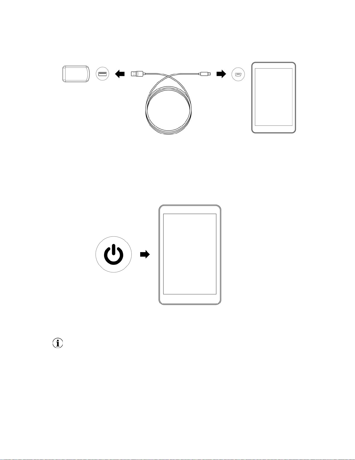
3.3.1. Charge the Programmer
To charge the programmer, connect the AC adapter and plug into an outlet (see figure below). Charge
the programmer when not in use so that there is enough battery power when using during a patient
session.
10 of 58 — 26-0009-7500/0 (OUS)
Physician’s Manual — VNS Therapy Programming System
Figure 2. Connect the Charger
3.3.2. Turn Programmer ON/OFF
To turn on the programmer, press and hold the power button for 3 seconds and then release (Figure 3).
A few seconds after releasing the power button, you will see an on-screen logo, followed by automatic
startup of the VNS software.
Figure 3. Power On Programmer
To turn off the programmer, press and hold the power button for 3 seconds and then release. Follow
on-screen instructions to shut down the programmer.
Note: The power button may not respond if the programmer is still shutting down.Wait for 30 seconds
after a shut down to restart the programmer.
3.3.3. Turn the Programmer Screen ON/OFF
Once the programmer is turned on, the screen will automatically turn off after 5 minutes of inactivity.
You can also turn the screen on or off by quickly pressing and releasing the power button. Use this
method when you want to preserve battery, but not shut down the programmer.
11 of 58 — 26-0009-7500/0 (OUS)
Physician’s Manual — VNS Therapy Programming System
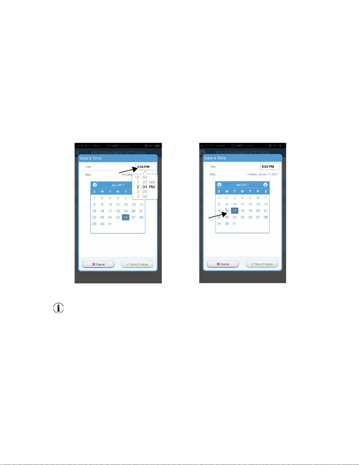
Select time to adjust time
Select day on calendar to adjust date
3.3.4. Check Programmer Battery
After VNS software startup is complete, the programmer battery status can be checked at any time by
viewing the indicator at the top right corner of any software screen. For more information, refer to
“How to Use the Software” on page 19.
3.3.5. Set the Programmer Date and Time
Accurate patient and device history stored in the programmer depends on correct time and date
settings. To adjust the date and time, select Settings from the bottom navigation bar, then Programmer
settings, and Date & Time. You can adjust the time by tapping the current display and scrolling up or
down. To change the date, use the left or right arrow to adjust the calendar, and then tap the desired
date. When finished, choose Save Changes. See Figure 4.
Figure 4. Adjust Programmer Time and Date
Note: The programmer does not automatically adjust for Daylight Saving Time or changes in time
zone. Adjust the time and date manually as needed.
3.3.6. Turn on Wand/Check Wand Battery
Turn the wand on by pressing and releasing the power button (Figure 5). If the battery is OK, green
lights will illuminate (Figure 6). If the battery is low, the low battery indicator will illuminate (Figure 7). If
the battery is low, replace the batteries by removing the cover located on the back of the wand
(Figure 8).
12 of 58 — 26-0009-7500/0 (OUS)
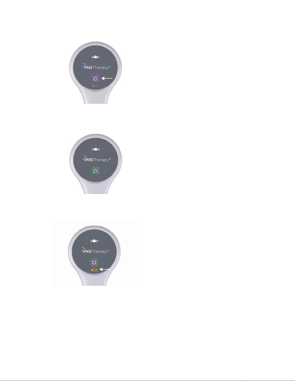
Figure 5. Power On Wand
Figure 6. Power Indicator (Battery OK)
Physician’s Manual — VNS Therapy Programming System
Figure 7. Low Battery Indicator
13 of 58 — 26-0009-7500/0 (OUS)
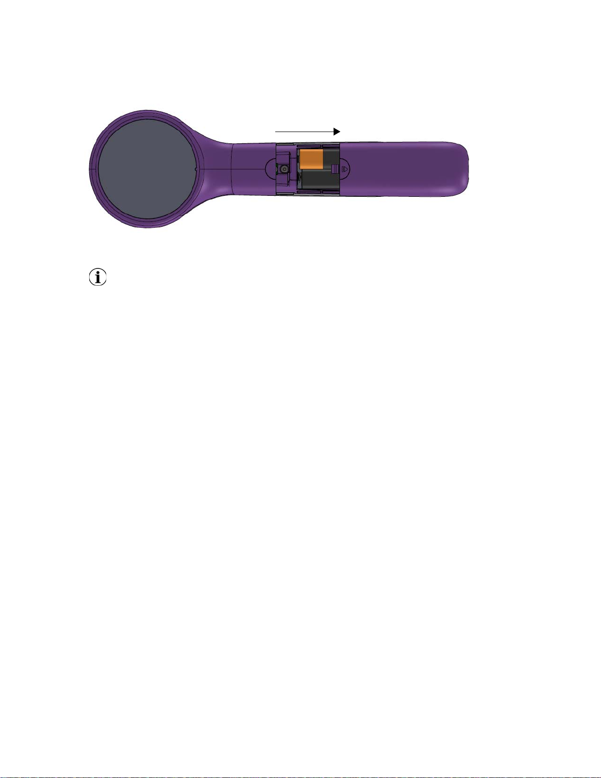
Figure 8. Wand Battery Replacement
Push and slide to open battery compartment
Bottom of Wand
Note: Once powered on, the wand will automatically power down (standby) after 60 seconds of
inactivity to conserve battery.
3.4. Connect Wand/Programmer
Physician’s Manual — VNS Therapy Programming System
The system allows you to connect the wand to the programmer wirelessly or with backup USB cable.
To connect wirelessly, you have two options:
Set up a preferred wand connection that is always used with that programmer. This setup is recommended
for wands and programmers that are always used together. It provides a quicker connection when
interrogating the patient's generator, since the programmer will automatically look for the preferred wand.
Choose a wand as part of interrogating the patient's generator. This method is recommended if you have
several interchangeable programming systems in your area. When interrogating a patient's generator, the
programmer will search for all available wands in range.
3.4.1. Preferred Wireless Wand Setup
To set up a preferred wireless connection between the wand and the programmer, do the following:
1. Power on the programmer
2. Select Settings from the bottom navigation bar
3. Power on the wand
4. Select the Wand Settings menu option, and enable the Preferred wand selection (while the wand is powered
on)
5. Select the desired wand serial number. Once connected, the software will show this serial number as your
preferred wand.
6. Use the back button (upper left) to return to the Main screen
3.4.2. Wired Wand Setup
Included with the system is a USB cable that connects the wand to the programmer. Use this as a back
up method when a wireless connection is not available. Once connected, the software will identify the
specific wand connected via the cable. After interrogate is selected, the four green indicators will light
up once the wand begins communicating with the generator. The green indicator lights will turn off
after 60 seconds of inactivity.
14 of 58 — 26-0009-7500/0 (OUS)
Physician’s Manual — VNS Therapy Programming System
4. INTERROGATING THE GENERATOR
4.1. Interrogate (No Preferred Wand)
You must interrogate the generator before performing other functions, such as applying new
parameters or performing diagnostics tests.
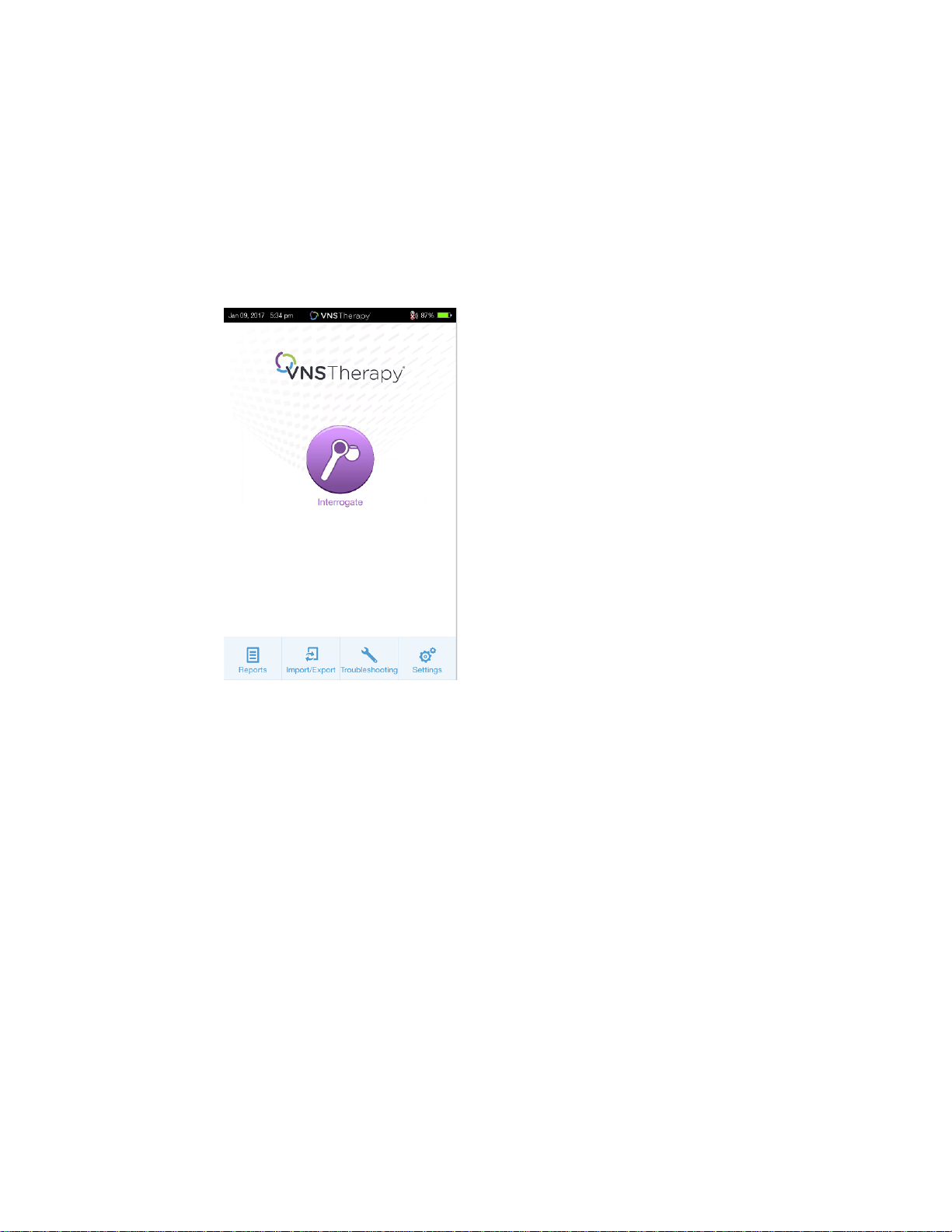
To begin, power on the programmer. Upon startup, the Main screen will display (Figure 9).
Figure 9. Main Screen
Next, turn on the wand by pressing and releasing the power button. Two green lights will illuminate
indicating the wand is ready to connect. While the green wand lights are illuminated (Figure 6), select
Interrogate on the programmer screen. The programmer will search for available wands. See Figure 10.
15 of 58 — 26-0009-7500/0 (OUS)
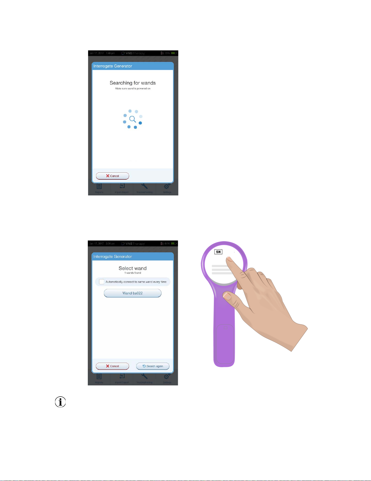
Figure 10. Wand Search Screen
SN location on back of Wand
ba022
Physician’s Manual — VNS Therapy Programming System
The programmer will show all powered-on wands in range. Select the wand you intend to use
(Figure 11), using the wand serial number (SN). The wand SN is located on the back of the wand.
Figure 11. Wand (SN) Selection Screen
Note: To use a specific want in subsequent sessions, check the “Automatically connect to the same
wand every time” box on the screen before choosing a wand.
Once the wand has connected, the software will indicate a successful connection and four green lights
will illuminate around the wand power button (Figure 12).
16 of 58 — 26-0009-7500/0 (OUS)
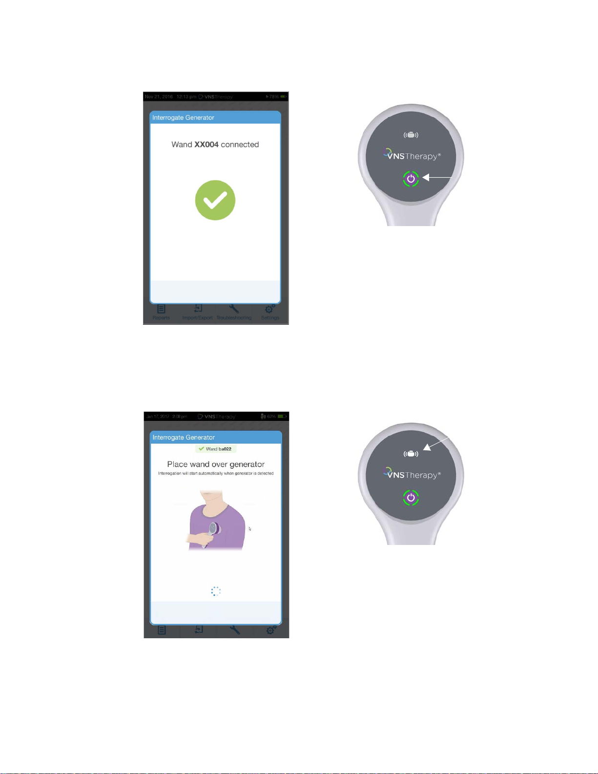
Figure 12. Successful Wand Connection
Successful wand connection lights illuminated
Generator icon will flash during interrogation
Physician’s Manual — VNS Therapy Programming System
Place the wand over the generator as shown on the software (Figure 13). Once the wand recognizes the
generator, the interrogation will complete and the software will display the summary screen. For more
details refer to “How to Use the Software” on page 19.
Figure 13. Interrogate Generator Screen
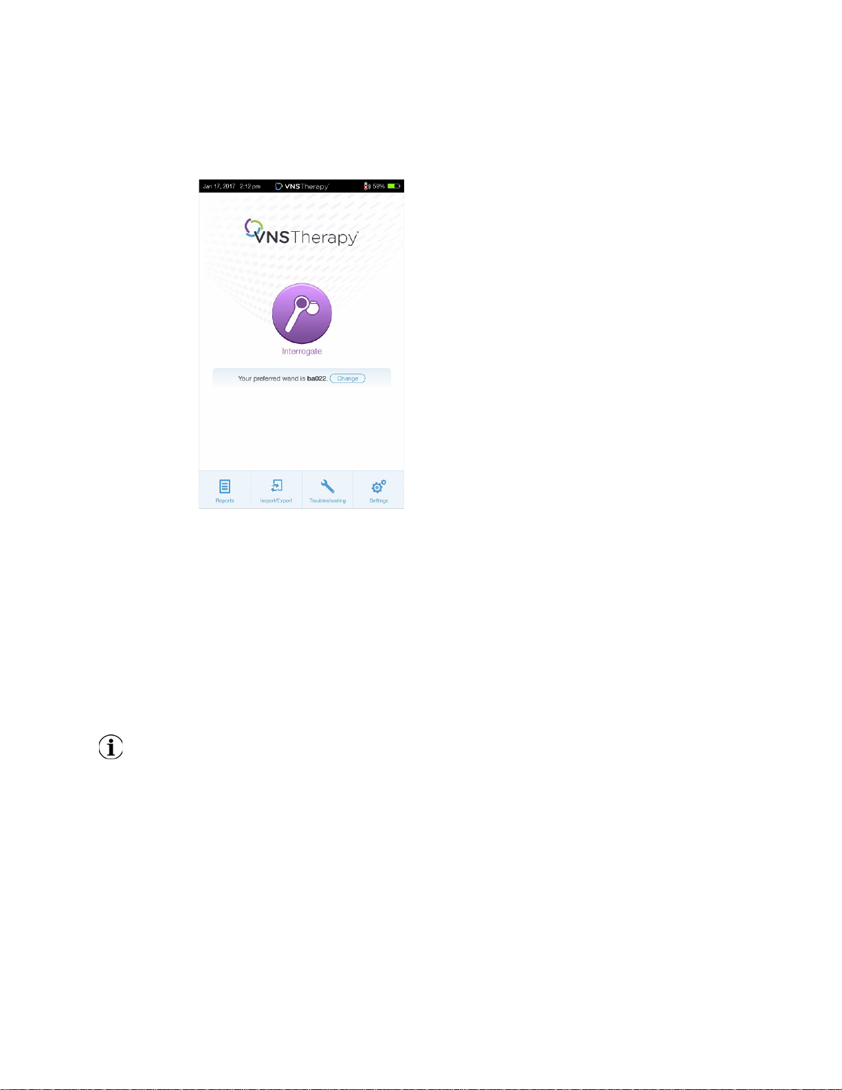
4.2. Interrogate (With Preferred Wand)
If you have set up a preferred wand, the programmer will automatically connect to that wand when you
press Interrogate.
17 of 58 — 26-0009-7500/0 (OUS)
Physician’s Manual — VNS Therapy Programming System
The main screen will display to the preferred wand information. See Figure 14. Make sure wand is
powered on before selection interrogate. After the programmer and wand are connected, place the
wand over the generator to complete the interrogation.
Figure 14. Main Screen - Preferred Wand
4.3. Interrogate (Change Preferred Wand)
If you have set up a preferred wand, but want to connect to a different wand, perform the following
steps:
1. Power on the new wand
2. Select the Change button on the Main Screen.
The programmer will search for all wands that are powered on and in range. Select the intended wand
serial number from the list. When you connect to the new wand, it will become the new preferred wand
and the programmer will automatically connect to it in future sessions. Place the wand over the
generator to complete the interrogation.
Note: To clear the preferred wand and connect manually, select Settings from the Main screen. Within the
Wand Settings, set the Preferred Wand status to Disabled. Select the back button on the upper left of the
screen to return to the Main screen. Next time you interrogate, manually connect to a wand following the
steps in “Interrogate (No Preferred Wand)” on page 15.
18 of 58 — 26-0009-7500/0 (OUS)

Physician’s Manual — VNS Therapy Programming System
5. HOW TO USE THE SOFTWARE
The VNS Therapy Software displays messages and prompts to guide you through the software.
5.1. Summary Screen
After a successful interrogation, the Summary screen will display. From this screen, you can perform the
following functions:
View generator ID information, including model number and serial number
View and edit patient data, such as patient ID and implant date
View last known diagnostics data, such as lead impedance and battery status
Change settings to generator parameters, such as Normal, Magnet, AutoStim, or Detection settings
Perform diagnostics
View events and trends such as magnet activations and daily average AutoStims
Access device history, including parameter settings associated with prior office visits
Interrogate the generator again to verify parameters or refresh data
End programming session
Access other software options
Note: The information displayed is specific to the generator model. Not all parameters will be
applicable for all generator models.
Note: An office visit is defined as any two interrogations separated by more than 12 hours.
19 of 58 — 26-0009-7500/0 (OUS)

Figure 15. Summary Screen
1. Current programmer date
and time
2. Wand connection and
programmer battery
status
3. Ends current session
4. Generator and patient
information
5. Interrogate generator
again
6. Last known diagnostics
measurements
7. View stimulation events
8. Current parameters
9. Navigation bar to
additional software
features
Physician’s Manual — VNS Therapy Programming System
5.2. Quick Access Bar
From any software screen, tap the VNS Therapy logo on the title bar at the top of the screen to access
programmer settings and system information (Figure 16). This drop-down bar shows the following:
Programmer date and time
Wand connection status
Programmer battery level
Sliders to adjust system volume and display brightness
Programming software version
Wand software version and generator firmware, when in-session (i.e. connected)
20 of 58 — 26-0009-7500/0 (OUS)

Figure 16. Quick Access Bar
Physician’s Manual — VNS Therapy Programming System
21 of 58 — 26-0009-7500/0 (OUS)
Physician’s Manual — VNS Therapy Programming System
6. PROGRAM THE DEVICE
To program any information into the patient's generator, you must interrogate the generator.
6.1. Edit Patient Data
For each patient's generator, enter the following information:
Patient ID: three alpha-numeric characters (maximum)
Implant date: the date the generator was implanted
After successful interrogation, the Patient ID, implant date, generator model, and serial number display
at the top of the Summary screen.
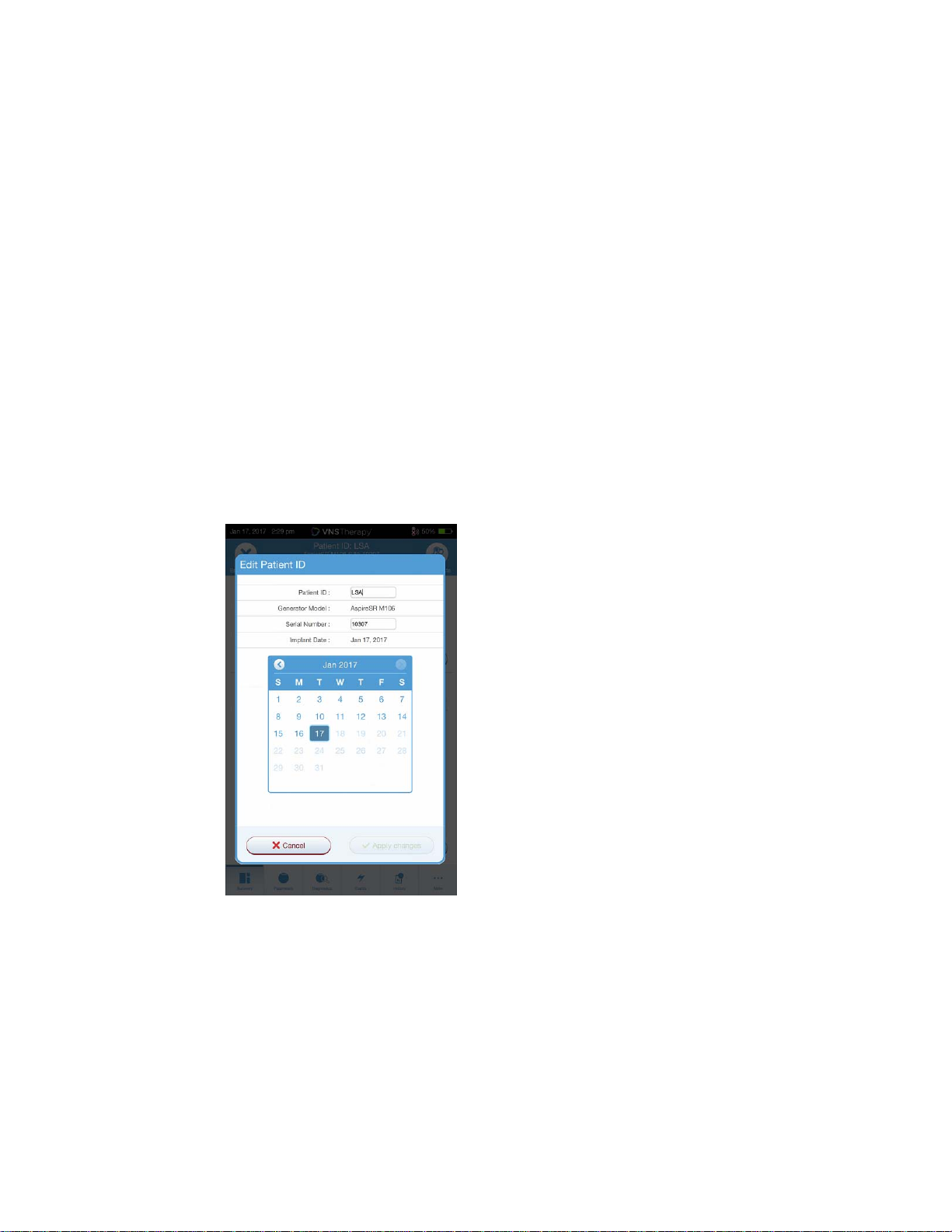
To enter or edit this information, do the following:
1. Interrogate the patient's generator
2. Review the generator information displayed at the top of the screen
3. Select “Edit” and enter the desired information (Figure 17)
4. Apply Changes and Confirm to program the information into the generator
Figure 17. Edit Patient ID Screen
6.2. How to Adjust Parameter Settings
After interrogation, the summary screen will display. To change generator settings from this screen,
select Edit parameter or select Parameter on the navigation bar at the bottom.
From the Parameters screen, you can change stimulation or detection parameters, depending on the
model of generator. Refer to the Technical Manual for a full list of programmable parameters available
for each generator. For models 102-105, only Normal Mode and Magnet stimulation parameters are
available. For models 106 and 1000, AutoStim and Detection parameters are also available. Detection
parameters will display on a separate tab. Review all tabs when adjusting parameters.
22 of 58 — 26-0009-7500/0 (OUS)

Physician’s Manual — VNS Therapy Programming System
To change a parameter setting, first select the tab of interest on the Parameter screen, and then follow
these steps:
1. Tap the Value for the parameter you want to change. A pop-up menu displays the range of possible values. If
there are values greater than or less than those shown on the screen you can view them by scrolling up or
down.
2. Select the new target value for the parameter. For Output Current, if the target value selected is greater than
0.25 mA compared to the currently programmed value in the generator, an Output Warning will appear
(Figure 18).
Note: LivaNova recommends that during the initial parameter adjustments after implant, the
output current be set to 0 mA and then slowly increased by 0.25 mA increments until the patient
feels the stimulation at a comfortable level. Patients who are receiving replacement generators
may also be started at 0 mA Output Current, followed by incremental increases of 0.25 mA to
allow for re-accommodation to the therapy.
Figure 18. Output Warning Screen
3. New parameter selections that have not been programmed to the generator are in green. Programmed,
unchanged, settings are in black.
4. Select Apply Changes at the bottom of the Parameter screen, to proceed to the Confirmation screen
(Figure 19).
5. Confirm the updated parameter setting(s) are correct. If correct, place the wand over the generator and select
Confirm to program the new settings to the generator. If incorrect, select Cancel to return to the Parameter
screen to make further adjustments.
6. Upon successful update to parameters, you will be notified with an on-screen message showing the newly
programmed parameter settings.
23 of 58 — 26-0009-7500/0 (OUS)

Figure 19. Confirmation Screen
Physician’s Manual — VNS Therapy Programming System
If any parameter changes were made during a particular patient visit, it is recommended to perform a
final interrogation prior to the end of the patient visit in order to confirm the generator is set to the
desired values. To perform the final interrogation, navigate to the Parameter screen and then press the
Interrogate button at the top right portion of the screen.
Caution: For models 102(R) generators, do not use frequencies of 5 Hz or less for long-term
stimulation. These frequencies always generate an electromagnetic trigger signal that results in
excessive battery depletion of the implanted generator; therefore, use these low frequencies for
short periods of time only.
Caution: Excessive stimulation is the combination of an excess duty cycle (i.e. one that occurs
when ON time is greater than OFF time) and high frequency stimulation (i.e. stimulation at ? 50
Hz). Excessive stimulation has resulted in degenerative nerve damage in laboratory animals.
Furthermore, excess duty cycle can be produced by continuous or frequent magnet activation (>
8 hours). While LivaNova limits the maximum programmable frequency to 30 Hz, it is
recommended that you do not stimulate with excess duty cycle. Physicians should also warn
patients about continuous or frequent magnet use as this could lead to early battery depletion.
[IS ALL THIS INFORMATION NECESSARY?]
6.3. How to Configure Seizure Detection Settings
You can adjust seizure detection settings under the Detection tab on the Parameter screen for models
106 and 1000 generators.
6.3.1. Turning the Detection Feature ON/OFF
You may enable or disable Detection. If Detection is Disabled, then the model 106 and 1000 generators
use only Normal and Magnet stimulation. If Detection is Enabled, then parameters for AutoStim will
become available, in addition to Normal and Magnet parameters.
Note: If Detection is disabled, the parameters on the Detection tab are not visible and AutoStim
is not activated.
24 of 58 — 26-0009-7500/0 (OUS)

Physician’s Manual — VNS Therapy Programming System
When you enable Detection for the first time, the software will prompt you to set the Heartbeat
Detection setting and AutoStim Threshold. These settings work together to ensure the generator is
accurately detecting the patient's heartbeats, and set the criterion for AutoStim delivery based on
changes in heart rate, respectively. Once Detection is enabled, you can adjust the settings from the
Detection tab as needed.
6.3.2. Set Heartbeat Detection
In order for the generator to accurately detect heartbeats, the heartbeat detection must be set for the
individual patient.
For model 106 and 1000 generators, you must manually select from a range of heartbeat detection
sensitivity values: 1 (least sensitive; for use with largest amplitude ECG signals) to 5 (most sensitive; for
use with smallest amplitude ECG signals). The setting will not change unless manually programmed to
a different value.
6.3.3. Use Verify Heartbeat Detection
When Detection is enabled, the software will walk you through heartbeat detection setting verification
and AutoStim threshold selection. Afterwards, select the Verify button on the Detection tab to confirm
the accuracy of the heart rate detected by the generator or to change the heartbeat detection setting.
To do so, complete the following steps:
1. Press Verify to advance to the Verify Heartbeat Detection screen (Figure 20). If Detection has been Enabled,
the Verify Heartbeat Detection screen will automatically display.
Figure 20. Verify Heartbeat Detection Screen
2. On the Verify Heartbeat Detection screen, tap the Heartbeat Detection setting field to change the value (if
desired). Place the wand over the generator and press Start to begin the test.
3. Keep the wand over the generator during the entire Verify Heartbeat Detection process. The generator will
transmit a signal and the programmer will display the detected heart rate in beats per minute (BPM) for up to
two minutes (Figure 21).
25 of 58 — 26-0009-7500/0 (OUS)

Physician’s Manual — VNS Therapy Programming System
Figure 21. Verify Heartbeat Detection - Test in Progress
4. Wait for the heart rate display to stabilize (at least 10 seconds) and compare the generator-detected heart
rate displayed on the programmer with an independent source (such as BPM from another ECG monitor or a
manual pulse count). Accurate detection should be within 10% or ±5 bpm, whichever is greater. If the heart
rate reported by the programmer is too high, then the Heartbeat Detection setting should be adjusted
downward (toward setting 1). If the heart rate reported by the programmer is too low, then the Heartbeat
Detection setting should be adjusted upward (toward setting 5). Refer “Troubleshooting” on page 42 for
more information.
5. If the heartbeat detection is verified before the end of two minutes, place the wand over the generator and
select Stop on the screen.
Once you observe accurate heartbeat detection, you have completed the verification process. If you are
enabling Detection, select Next to set the AutoStim Threshold. Otherwise, select Done to return back to
the Parameter screen.
6.3.3.1. Visual Indicators During Verify Heartbeat Detection
During heartbeat verification, the following visual indicators will display in the BPM window:
?? indicates lost/no communication, or no heart beats detected by the generator
<40 BPM will display if the system detects a heart rate below 40 BPM
>230 BPM will display if the system detects a heart rate above 230 BPM
Between 40-230, the system-calculated heart rate will display
Caution: For Model 106, if AutoStim or Magnet stimulation is programmed on, the Verify Heartbeat
Detection feature may be interrupted if AutoStim or Magnet stimulation is activated during the Verify
Heartbeat Detection Process. In this case, ?? will display on the screen. If ?? displays, LivaNova
recommends you temporarily disable all output currents for the model 106 (i.e. programmed to 0 mA)
and retry the heartbeat verification. After the calibration process is completed, you may reprogram
the output currents as appropriate.
6.3.4. Set the AutoStim Threshold
The AutoStim Threshold is a setting on the Detection tab that can be set from 20% to 70% (in 10%
increments). This setting allows you to determine minimum heart rate change required for AutoStim,
26 of 58 — 26-0009-7500/0 (OUS)

Physician’s Manual — VNS Therapy Programming System
and should be tailored to the individual patient. For the most sensitive detection and the smallest heart
rate change for stimulation, choose 20%. For the least sensitive detection and thus the largest heart
rate change for stimulation, choose 70%.
Note: Additional guidance for how to program this patient-specific setting can be found in the VNS
Therapy System Physician's Manual.
6.3.5. Stimulation Settings on the AutoStim Tab
The AutoStim parameter settings determine the stimulation output delivered when AutoStim
Threshold is reached. Alter these settings from the stimulation tab on the Parameter screen.
6.3.5.1. Detection and Time Restraints
In order to allow enough detection time between scheduled stimulation periods, the programming
software will not allow you to program certain combinations of Normal Mode and AutoStim values. If
you program a Normal Mode Off Time of 1.1 minutes or less while AutoStim/ Detection is enabled, you
will be prompted to change the values. Otherwise, detection will be turned OFF at the next
programming attempt.
Caution: LivaNova recommends you monitor the patient briefly after parameter changes to ensure
stimulation is tolerable. LivaNova also recommends the output current for the AutoStim Mode does
not exceed the output current for the Normal Mode or the Magnet Mode, especially for patients who
experience discomfort.
6.4. Potential Error Conditions Related to Programming
6.4.1. Partial Programming (Model 102R)
Each parameter is programmed and verified individually during a programming event for model 102(R)
generators. If the communication is interrupted during programming, generators can be set to
unintended settings. The software will display a warning message indicating that the programming
failed and device settings were altered or potentially altered due to the interrupted programming
attempt. If this occurs, you should interrogate the generator immediately to verify current programmed
settings. If necessary, reprogram to desired settings.
6.4.2. Partial Programming Interruption (Models 103-106 and 1000)
For models 103-106 and 1000 generators, the device parameters are programmed and verified as a
group during a programming event, which is not susceptible to partial programming. If an interruption
occurs during programming, the software will display a warning message indicating that the procedure
failed and allows the user to retry or cancel the programming operation (Figure 22). If you decide to
cancel, interrogate the generator to verify settings before reattempting the programming operation.
27 of 58 — 26-0009-7500/0 (OUS)

Physician’s Manual — VNS Therapy Programming System
Figure 22. Programming Failed Warning Screen
6.4.3. Cross-programming (Model 102 Generators ONLY)
Model 102(R) generators are susceptible to an event known as cross-programming. This occurs when
parameter settings from a patient's generator are inadvertently programmed to another patient's
generator. This can happen if you don’t interrogate the generator between patients visits and both
patients have the model 102 or 102R generator. Always perform an initial and final interrogation to
verify parameter settings at each office visit for all patients.
28 of 58 — 26-0009-7500/0 (OUS)

7. GUIDED PROGRAMMING
Physician’s Manual — VNS Therapy Programming System
29 of 58 — 26-0009-7500/0 (OUS)

8. SCHEDULED PROGRAMMING
Physician’s Manual — VNS Therapy Programming System
30 of 58 — 26-0009-7500/0 (OUS)

9. DAY /NIGHT PROGRAMMING
Physician’s Manual — VNS Therapy Programming System
31 of 58 — 26-0009-7500/0 (OUS)
Physician’s Manual — VNS Therapy Programming System
10. DEVICE DIAGNOSTICS
Several Diagnostics tests are available in the programming software to assess functionality of the
implanted system. You may access them after a completed interrogation by selecting Diagnostics, or
Perform Diagnostics on the Summary screen (see Figure 23).
Figure 23. Accessing Diagnostics
Depending on the model of generator interrogated, you may have access to different types of tests.
Typical tests include System Diagnostics, Normal Mode Diagnostics, Magnet Diagnostics, and AutoStim
Diagnostics. Make sure to follow all the instructions on the programmer screen, as they vary for each
selection.
It's important to note that the tests described in this section are designed for assessing system
functionality using the implanted components. Another test, Generator Diagnostics, is designed
specifically for use with a test resistor and should only be accessed for troubleshooting scenarios
during implantation surgery. Please see “Troubleshooting” on page 42 for more details on accessing
Generator Diagnostics.
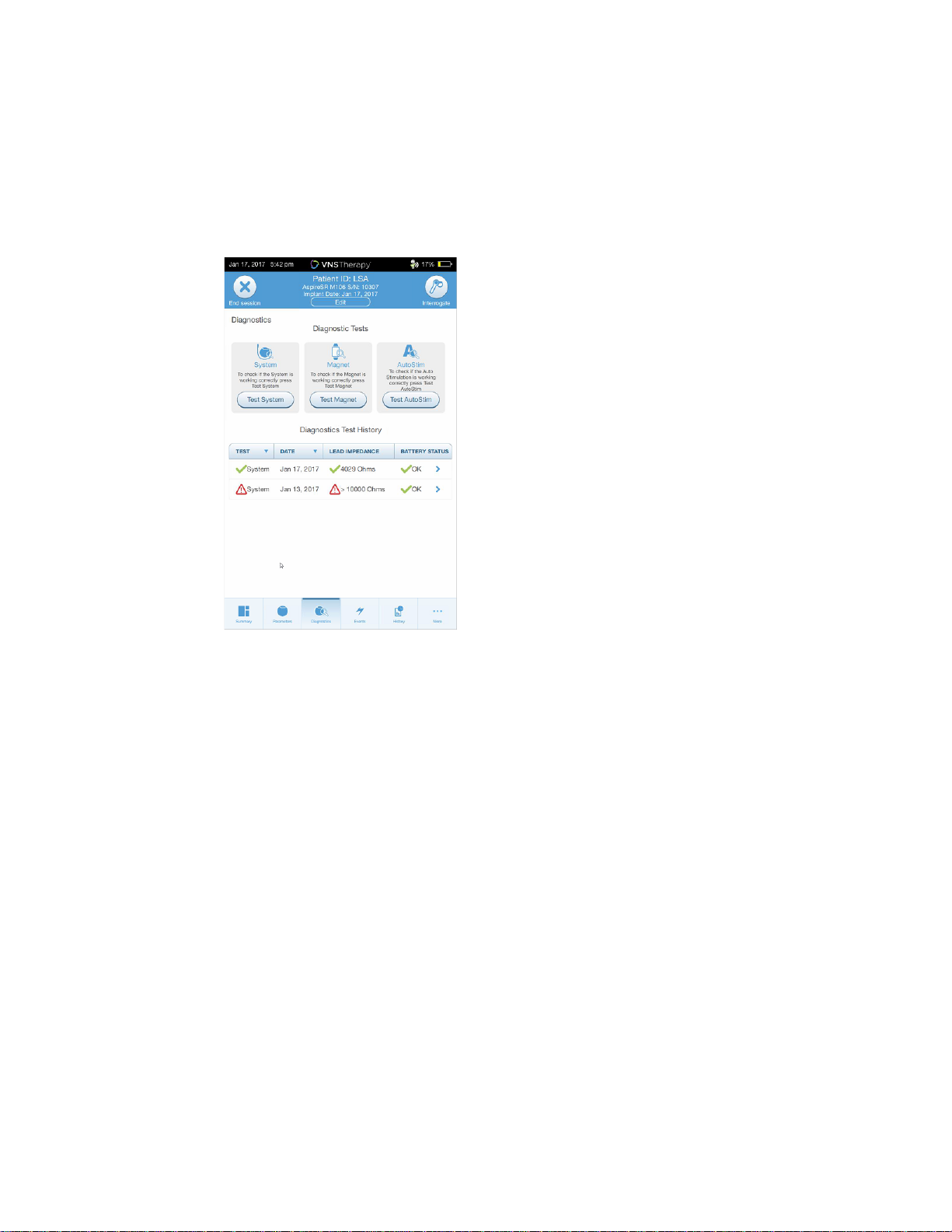
10.1. Reading Test Results
Figure 24 shows a typical results screen after completion of a diagnostics test.
32 of 58 — 26-0009-7500/0 (OUS)

Figure 24. Diagnostics Results Example
Physician’s Manual — VNS Therapy Programming System
The various test parameters and their values/meanings across the different diagnostics tests are
summarized in the Table 1. Additional details regarding specific diagnostics tests are further detailed in
the remaining sections of this physician's manual. For model102 generators, the lead impedance values
are estimated based on DC DC code (displayed in previous versions of VNS software) and the
conversion between DC DC code and estimated impedance range are listed in Table 2. For abnormal
result, refer to the “Troubleshooting” on page 42, for additional instructions.
Table 1. Diagnostic/Parameter Result Summary
Parameter Name(s) Parameter Description
Lead Impedance Indicates measured or
estimated impedance when
delivering the output
current during testing and
whether it's within normal
range.
Parameter Values/
Results
M103-106 and 1000:
Measured lead impedance
value (ohms) and overall
status of OK, LOW, or HIGH
M102: Estimated lead
impedance range (ohms)
and overall status of OK,
LOW, or LIMIT
What Does the Value or
Result Mean?
OK: Impedance is within
acceptable operating range.
No special attention is
required.
LOW: Impedance is lower
than expected and it may
be indicative of a short
circuit condition or a
defective generator. See
Section 14, Troubleshooting
for additional instructions.
HIGH or LIMIT: Impedance
is higher than expected and
the generator may not be
able to deliver the
programmed therapy. See
Section 14, Troubleshooting
for additional instructions.
33 of 58 — 26-0009-7500/0 (OUS)

Physician’s Manual — VNS Therapy Programming System
Parameter Name(s) Parameter Description
Generator Battery Indicates battery status of
the generator using one of
the following:
OK
Intensified Follow-up
Indicator (IFI)
Near End of Service (N
EOS)
End of Service (EOS)
Parameter Values/
Results
M103 and subsequent
models:
OK
IFI = Yes
N EOS = Yes
EOS = Yes
M102:
OK
N EOS = Yes
What Does the Value or
Result Mean?
OK: Battery level is within
normal operating range and
no special attention is
required.
IFI = Yes: The battery has
depleted to a level where
more
frequent clinical monitoring
is recommended.
N EOS = Yes:
M103 and subsequent
models: The Generator
should be replaced as soon
as possible.
M102: A System
Diagnostics Test is
recommended to verify the
Near EOS status. If
confirmed, the pulse
generator should be
replaced as soon as
possible.
Output Current / Current
Delivered
Indicates the stimulation
output current applied /
delivered during the
diagnostics test, and overall
status of whether the
current was delivered
EOS = Yes: The generator is
no longer supplying
stimulation and immediate
replacement is
recommended. If the
generator is not replaced, it
will eventually lose the
ability to communicate with
the software.
Parameter value Indicates the stimulation
output current applied /
delivered during the
diagnostic test.
OK: Current is being
delivered at the
programmed level.
M103-106 and 1000:
LOW: Programmed current
is possibly not being
delivered at the specified
level.
M102:
Limit: Programmed current
is possibly not being
delivered at the specified
level.
34 of 58 — 26-0009-7500/0 (OUS)

Physician’s Manual — VNS Therapy Programming System
Caution: Battery depletion can occur between visits and may not be detected by the various battery
indicators. Therefore, for patients with magnet activation enabled, LivaNova recommends a daily
magnet activation by the patient as a means to check stimulation and to consult with the physician to
perform diagnostics testing if patient no longer feels stimulation.
Table 2. DC DC Code Conversion and Estimated Impedance Range
DC DC Code Estimated Impedance Range
0 <1.7 kΩ*
1 1.8-2.8 kΩ*
2 2.9-4.0 kΩ*
3 4.1-5.2 kΩ*
4 5.3-6.5 kΩ*
5 6.6-7.7 kΩ*
6 7.8-8.9 kΩ*
7 >9.0 kΩ*
*Correspondence to estimated lead impedance value at 1mA,
500μs
10.2. System Diagnostics
The System Diagnostics test assesses the electrical continuity between the generator and the bipolar
lead when connected. The test measures the generator's ability to deliver programmed output current
and the lead impedance status. A successful System Diagnostics during surgery or post-implant shows
that both the generator and lead are working properly.
You can perform this test on all generators supported by the VNS Programming Software during
implantation and patient follow-up visits. LivaNova recommends you perform this test before other
diagnostic tests.
10.3. Normal Mode Diagnostics (Model 102)
The Normal Mode Diagnostics test will let you know if the generator is ready to deliver output current.
Perform this test regularly at follow-up visits only if the patient can tolerate at least .75 mA. Any setting
less than 0.75 mA with a frequency less than 15 Hz or ON time less than 30 sec will render an unreliable
test result. Make sure the patient’s settings meets the minimum requirement.
Note: For models 103-106 and 1000 generators, the System Diagnostics test serves the same function
as Normal Mode Diagnostics since the test is run at the programmed device settings.
10.4. Magnet Mode Diagnostics
The Magnet Mode Diagnostics test will let you know if the generator is delivering the programmed
magnet output current. To do perform this rest, pass the magnet over the generator for at least one
second and then place the wand over the generator. This action will enable stimulation at the
programmed Magnet Mode output current. If you perform this incorrectly, the test will be invalid and a
message will display on the screen indicating the magnet swipe was not detected. Pass the magnet
over the generator again to restart the test.
35 of 58 — 26-0009-7500/0 (OUS)

Physician’s Manual — VNS Therapy Programming System
For the model 106 generator, do not leave the magnet over the generator for longer than 3 seconds
when performing the Magnet Mode Diagnostics. Otherwise, stimulation will stop and the Magnet
Mode Diagnostics results will invalid. In addition, similar to Normal Diagnostics, any setting less than
0.75 mA with a frequency less than 15 Hz or ON time less than 30 sec will result in an unreliable test.
Make sure the patient's settings meet the minimum requirement.
10.5. AutoStim Diagnostics (Model 106 and 1000)
The AutoStim Diagnostics test determines whether the device is delivering the programmed AutoStim
output current. The desired AutoStim current should be programmed before you perform the
AutoStim diagnostic. The result will indicate whether the programmed AutoStim current is being
delivered given the lead impedance that is present.
10.6. Generator Diagnostics
The Generator Diagnostics test is designed specifically for use with a test resistor and should only be
accessed for troubleshooting scenarios during implantation surgery. Please see “Troubleshooting” on
page 42 for more details on using Generator Diagnostics.
10.7. Diagnostic Test Differences Between Models of Generators
Some Diagnostic tests operate differently depending on which model generator is used. These
differences are outlined below in Table 3.
Table 3. Diagnostic Test Differences Between Models of Generators
Items of Interest Model 102(R) Models 103-106 and 1000
Parameter Settings During System
Diagnostics
Parameter Settings During Generator
Diagnostics
Lead Impedance Lead impedance is not directly
Stimulates at 1.0mA, 500
Caution: Patients with lower
parameter settings may feel
discomfort during this test.
Stimulates at 1.0mA, 500
Hz.
Caution: The Generator
Diagnostics test should only
be run in the operating room
setting with the test resistor.
Caution: The model 102
generator will be set to 0mA
after the test.
measured. Instead, a DC-DC Converter
Code is reported and is indicative of
the estimated lead impedance at 1mA
and 500μs.
μs, and 20 Hz
μs, and 20
Normal Mode Output Current is
programmed to 0mA: Stimulates at
1.0mA, 500μs, and 20Hz.
Normal Mode Output Current is
programmed to > 0mA: Stimulates at
the programmed Normal Mode
parameters
Normal Mode Output Current is
programmed to 0mA: Stimulates at
0.25mA
Normal Mode Output Current if
programmed to > 0mA: Stimulates at
the programmed Normal Mode
parameters.
The actual lead impedance
measurement is reported.
36 of 58 — 26-0009-7500/0 (OUS)

Physician’s Manual — VNS Therapy Programming System
10.8. Potential Error Conditions Observed in Diagnostics
If diagnostics testing is interrupted, follow on-screen instructions to repeat the test and verify the
patient's parameters. The model 102 parameters are especially susceptible to be changed to
unintended settings during an interrupted diagnostic test due to the break in communication between
the programmer and the wand; therefore, it's especially important to re-verify the patient's parameters
after a diagnostic test interruption. Always re-interrogate to verify settings after an interrupted
diagnostics test.
37 of 58 — 26-0009-7500/0 (OUS)

11. HISTORY
Physician’s Manual — VNS Therapy Programming System
38 of 58 — 26-0009-7500/0 (OUS)

12. EVENTS AND TRENDS
Physician’s Manual — VNS Therapy Programming System
39 of 58 — 26-0009-7500/0 (OUS)

Physician’s Manual — VNS Therapy Programming System
13. MANAGING PROGRAMMER INFORMATION
40 of 58 — 26-0009-7500/0 (OUS)

14. PROGRAMMER SETTINGS
Physician’s Manual — VNS Therapy Programming System
41 of 58 — 26-0009-7500/0 (OUS)

Physician’s Manual — VNS Therapy Programming System
Issue
Non-responsive Programmer or Wand
Solution Steps for Programmer:
Charge programmer – Plug programmer into A/C outlet
Shut down – Press hold the power button for 3 seconds, and
then release. Follow on-screen instructions to shut down. If
programmer is still non-responsive, press and hold power button
for 5 seconds and then release to force a shut down.
Reboot – Power on the programmer
Solution Steps for Wand:
Verify wand battery power - If the red low battery light is on,
replace the wand batteries
Perform soft reset - Press and hold wand power button for 3
seconds and release
Contact LivaNova
Technical Support
No
Verify:
Programmer has
adequate charge
Programmer has
correct date/time
Yes
Device
Responsive?
Proceed with intended use
Yes
15. TROUBLESHOOTING
This section provides solution steps to resolve error conditions with the programming system
components or with the implanted generator and lead. For other programming system issues not
included in this section, contact LivaNova.
15.1. Non-responsive Programmer or Wand
If your programmer or wand becomes non-responsive, follow the solution steps in the figure below.
Figure 25. Solution Steps for a Non-responsive Programmer or Wand
15.2. Communication Issues
15.2.1. Wand Not Connecting to Programmer (Wireless)
Potential reasons for no wireless connection between the wand and the programmer include the
following:
Wand not powered on
Depleted wand battery
Electromagnetic interference (EMI), such as OR lights
Defective wand or programmer
42 of 58 — 26-0009-7500/0 (OUS)

Physician’s Manual — VNS Therapy Programming System
Error Messages
“No wands found…”
“Wand (serial number of connected
wand) not found”
Check Wand Power
Press and release power button.
Retry connecting to wand
Yes
Replace batteries
No
Does wand
power
indicator light
appear?
Successful
Connection?
Proceed with intended use
Verify Wand Selection
Confirm wand ID matches wand
selected on programmer
Check for Interference
Confirm wand is 3-4 feet away from
all electronic equipment
Reconnect to Wand
No
Yes
Successful
Connection?
No Yes
Connect with backup cable
Successful
Connection?
No Yes
Contact LivaNova
Technical Support
See Figure 26 for solution steps to resolve problems between the wand and programmer via wireless
connection.
Figure 26. Solution Steps For Wand Not Connecting to Programmer (Wireless)
15.2.2. Wand Not Connecting to Programmer (Backup Cable)
Potential reasons for no connection between the wand and the programmer via backup cable include
the following:
43 of 58 — 26-0009-7500/0 (OUS)

Physician’s Manual — VNS Therapy Programming System
Error Messages
“Wand not connected…”
Check Wand Power
Press and release power button
Retry connecting to wand
Yes
Replace batteries
No
Does wand
power
indicator light
appear?
Successful
Connection?
Proceed with
intended use
Verify Cable Connection
Confirm cable is connected to wand
and programmer. Reinsert if
necessary.
No
Yes
Successful
Connection?
No Yes
Contact LivaNova
Technical Support
Improper cable connection between wand and programmer
Depleted wand battery
Improper USB port recognition of the programmer cable
Defective wand or programmer
See Figure 27 for solution steps to resolve problems between the wand and programmer via backup
cable connection.
Figure 27. Solution Steps for Wand Not Connecting to Programmer (Backup Cable)
15.2.3. Wand Not Communicating with Generator
Potential causes for communication issues between the wand and generator include the following:
Depleted wand batteries
Moving wand away from generator during communication
Electromagnetic interference (EMI), such as OR lights
Generator battery at End of Service (EOS)
44 of 58 — 26-0009-7500/0 (OUS)

Physician’s Manual — VNS Therapy Programming System
Error Messages
“Generator not found...”
“Error communicating with
generator…”
Check Wand Placement
Confirm wand is placed over the generator
Rotate wand 45 degrees
Confirm generator pocket is not more than 1 inch below
the skin, not muscle (during surgery)
Retry Communication
Proceed with session
Yes
Contact LivaNova
Technical Support
No
Successful
Communication?
Defective wand, programmer, or generator
See Figure 28 for solution steps to resolve communication problems between the wand and generator.
Figure 28. Solution Steps for Wand Not Communicating with Generator
15.3. High/Low Lead Impedance and Low Output Current Issues
15.3.1. High Lead Impedance in the OR
If a system diagnostics test results in high lead impedance, the following are possible causes:
Improper connection between the lead and the generator
Incorrect placement of lead on the nerve (initial implant only)
Allowing nerve to become dry (initial implant only)
Defective lead or generator
See Figure 29 for solution steps.
45 of 58 — 26-0009-7500/0 (OUS)

Physician’s Manual — VNS Therapy Programming System
Error message
Lead Impedance “HIGH”
Verify Lead Insertion into Generator
Back out setscrew(s), remove lead pin(s), and leave the hex screwdriver engaged in setscrew(s).
Verify the setscrew(s) is not visible in the lead receptacle(s).
Insert connector pin(s) and tighten setscrew(s) until the hex screwdriver clicks.
Confirm the lead pin(s) is past the back end of the connector block.
For single-pin generators, verify the end of the connector ring is inside of the lead receptacle.
For Initial Implant: Irrigate dry nerve site and remove pooled fluid if necessary.
Verify proper lead electrode placement on the nerve.
Retry System Diagnostics.
Troubleshoot Generator
Back out setscrew(s) and remove
lead pin(s).
Insert test resistor into generator
and tighten setscrew(s) with hex
screwdriver until the screwdriver
clicks.
Select More Troubleshooting
on the programmer.
Select Generator Diagnostics
Start on the programmer.
Proceed with implant.
Contact LivaNova Technical
Support
“OK”
“HIGH”
Reinsert Lead into Generator
Back out setscrew(s) and remove test resistor.
Verify the setscrew(s) is not visible in the lead receptacle(s).
Engage the hex screwdriver in the setscrew(s).
Insert connector pin(s) and tighten setscrew(s) until the hex
screwdriver clicks.
Visually inspect the lead receptacle(s) and verify that the
lead pin(s) is past the back end of the connector block(s).
Retry System Diagnostics.
Proceed with implant.“HIGH” “OK”
Lead
Impedance
Value?
“HIGH”
“OK”
Lead
Impedance
Value?
Lead
Impedance
Value?
Figure 29. Solution Steps for High Lead Impedance in OR
15.3.2. Low Lead Impedance in OR
If a system diagnostics test results in low lead impedance, the following are possible causes:
During Initial Implant
Incorrect placement of the lead on the nerve
Excessive irrigation of the nerve
Defective generator or lead
During Generator Replacement
Short-circuit condition within the lead
Defective generator
See Figure 30 for solution steps.
46 of 58 — 26-0009-7500/0 (OUS)

Physician’s Manual — VNS Therapy Programming System
Error message
“Lead Impedance “LOW”
Troubleshoot Generator
Back out setscrew(s) and remove lead pin(s).
Insert test resistor into generator and tighten
setscrew(s) with hex screwdriver until the screwdriver
clicks.
Select More Troubleshooting on the programmer.
Select Generator Diagnostics Start on the
programmer.
“LOW”
Lead
Impedance
Value?
Contact LivaNova Technical
Support
Initial Implant Generator Replacement
Type of
Implant?
Check the Lead
Verify lead electrodes have been correctly placed
on the nerve.
Remove pooled fluid if nerve site is saturated.
Retry System Diagnostics
Lead
Impedance
Value?
Proceed with Implant
“OK”
“LOW”
“OK”
Initial Implant
Generator Replacement
Type of
Implant?
Reinsert Lead into Generator
Back out setscrew(s) and remove test resistor.
Verify the setscrew(s) is not visible in the lead receptacle(s).
Engage the hex screwdriver in the setscrew(s).
Insert connector pin(s) and tighten setscrew(s) until the hex
screwdriver clicks.
Visually inspect the lead receptacle(s) and verify that the
lead pin(s) is past the back end of the connector block(s).
Retry System Diagnostics.
Lead
Impedance
Value?
Proceed with Implant
“OK”
“LOW”
Figure 30. Solution Steps for Low Lead Impedance in OR
15.3.3. High Lead Impedance at Follow-up Visits (Model 102)
Possible causes for high lead impedance at follow-up visits for the model 102 generator include the
following:
47 of 58 — 26-0009-7500/0 (OUS)

Physician’s Manual — VNS Therapy Programming System
Error message
Lead Impedance “HIGH”
Perform a Systems Diagnostic
and Normal Mode Diagnostics
and record all results.
Systems Diagnostics Results =
Output Status: LIMIT
Lead Impedance: HIGH
Normal Mode Results =
Output Status: LIMIT
Yes
Systems Diagnostics Results =
Output Status: OK
Lead Impedance: HIGH
Normal Mode Results =
Output Status: LIMIT
Systems Diagnostics Results =
Output Status: OK
Lead Impedance: OK
Normal Mode Results =
Output Status: LIMIT
Systems Diagnostics Results =
Output Status: OK
Lead Impedance: OK
Normal Mode Results =
Output Status: OK
Near End
of
Service?
No
Contact LivaNova
Technical Support
Possible lead discontinuity, lead disconnection
from the generator, fibrosis between the nerve and
electrode, electrode detachment from the nerve, or
a defective generator.
Generator cannot deliver
programmed output. Reduce
output current or frequency
and widen pulse width.
Generator is performing as
intended
Replace generator
as soon as possible
Evaluate results
Lead discontinuity
Lead disconnected from generator
Fibrosis between nerve and electrode
Electrode detachment from nerve
Defective generator
High battery impedance, generator approaching EOS
See Figure 31 for solution steps.
Figure 31. Solution Steps for High Lead Impedance at Follow-up Visits (Model 102)
15.3.4. High/Low Lead Impedance or Low Output Current at Follow-up Visit (Models
103-106 and 1000)
Possible causes for high or low lead impedance or low output current at follow-up visits for models 103106 and 1000 generators include the following:
Lead discontinuity
48 of 58 — 26-0009-7500/0 (OUS)

Physician’s Manual — VNS Therapy Programming System
Error message
”A LOW Lead Impedance has
been detected...”
Lead Impedance “LOW”
Perform a Systems Diagnostics.
Record results.
Possible Causes:
Lead discontinuity
Lead disconnection
from the generator
Fibrosis between the
nerve and electrode
Electrode detachment
from the nerve
Defective generator
Contact LivaNova Technical Support
Possible Causes:
Lead discontinuity
Lead disconnection
from the generator
Fibrosis between the
nerve and electrode
Electrode detachment
from the nerve
Defective generator
Possible Cause:
Increased impedance
in the system
Possible Causes:
Short-circuit condition
within the lead
Defective generator
Error message
”A HIGH Lead Impedance has
been detected...”
Lead Impedance “HIGH”
Error message
”Programmed current is possibly not
being delivered...”
Output Current “LOW”
Generator is
delivering
stimulation as
intended.
System
Diagnostics
Values
Lead Impedance “OK”
Output Current “OK”
Lead Impedance “OK”
Output Current “LOW”
Lead Impedance “LOW”
Output Current “OK”
Lead Impedance “HIGH”
Output Current “LOW”
Lead Impedance “HIGH”
Output Current “OK”
Lead disconnected from generator
Fibrosis between nerve and electrode
Electrode detachment from nerve
Defective generator
Short-circuit condition within the lead
See Figure 32 for solution steps.
Figure 32. Solution Steps for High/Low Lead Impedance or Low Output Current at
Follow-up Visit (Models 103-106 and 1000)
15.4. Generator Battery Issues
15.4.1. Low Battery/End of Service Indications in OR
If a generator displays a low battery or End of Service (EOS) indicator while implanting, the possible
causes include the following:
Prior to Surgery:
Generator has been recently exposed to low storage temperatures
49 of 58 — 26-0009-7500/0 (OUS)

Physician’s Manual — VNS Therapy Programming System
Perform System Diagnostics or Generator
Diagnostics with device in sterile package.
Record results.
Lead Impedance “any”
Impedance Value “any”
IFI = No
Proceed with
implant.
Wait approximately 30 minutes
with generator at room
temperature.
Diagnostic
Results
Contact LivaNova Technical
Support
Error Message
“Generator Battery N EOS…”
“Generator Battery EOS…”
“Frequent monitoring recommended. The
Intensified Followup Indicator (IFI) is set…”
“Generator disabled…
Same battery status
indicator or warning
message as above
Number of
attempts
1 2
Defective generator
During Surgery:
Electrosurgical equipment used near the generator
Generator exposed to electrostatic discharge (ESD)
See Figure 33 for solution steps.
Figure 33. Solution Steps for Low Battery/End of Service Indications in OR
15.4.2. New Generator Disabled Due to EOS at First Interrogation
Generator models 103-106 and 1000 batteries can temporarily drain and become disabled if exposed
to certain conditions. These conditions include the following:
Electrosurgical equipment used near the generator
Generator exposed to electrostatic discharge (ESD)
See Figure 34 for solution steps.
50 of 58 — 26-0009-7500/0 (OUS)

Physician’s Manual — VNS Therapy Programming System
Error message
“Generator is currently disabled...”
Contact LivaNova Technical
Support
Enable Stimulation and Check System
Select OK
Enter desired parameters
Select Apply Changes
Perform System Diagnostics Test
Battery
Status?
Proceed with intended use
Monitor Patient for low
battery indicators
Note: Battery life will be
shortened
“IFI”=Yes or No “N EOS”=Yes or “EOS”=Yes
Replace Generator immediately
All Other Errors
Figure 34. New Generator Disabled Due to EOS at First Interrogation
15.4.3. Sudden Decrease In Remaining Battery Power
If the generator battery suddenly decreases at an office visit, the following are possible causes:
First visit after VNS or other surgery: exposure to specific conditions in the OR (see Low Battery/End of Service
Indications in OR) during surgery. If this condition occurred and was not detected in the OR, it is possible you
may detect this at the follow up visit. Device will still function normally, but will have decreased battery life.
Monitor the patient closely for any low battery indicators.
Significant change in the lead impedance or increase in programmed stimulation parameters can also result
in a change in the estimated battery power remaining. Evaluate battery power remaining between
consecutive patient visits before adjusting stimulation parameters. Review lead impedance for any
significant changes.
If any device issue is suspected, contact LivaNova Technical Support.
15.5. Heartbeat Detection Issues
15.5.1. Heartbeat Detection Inaccurate (Over/Under) in OR or at Follow-up Visit
The heartbeat detection setting may need to be adjusted to correctly detect heartbeats. See Figure 35
for solution steps to correct an over/under detection reading.
Note: The wand must be held over the generator during the entire Verify Heartbeat Detection
process.
51 of 58 — 26-0009-7500/0 (OUS)

Physician’s Manual — VNS Therapy Programming System
Heartbeat Detection is inaccurate
BPM is too high, low, ***** or ‘?????’
Check Hardware
Confirm the programmer is not plugged into a wall outlet.
Check Software
Confirm Detection is enabled.
Check Wand Placement
Verify wand is over the generator
Check Verify Heartbeat Mode
For Model 1000, switch to manual Verify Heartbeat
Adjust Heartbeat Detection
setting upward
(toward “5”).
Low
Adjust Heartbeat Detection
setting downward
(toward “1”).
Confirm accuracy in different
body positions (e.g. off-the-shelf
heart rate monitor or ECG).
No
Done.Yes
BPM?
OK?
High
Yes
Contact LivaNova Technical
Support
Retry with
different
settings.
All settings
attempted with
out success?
No
*****/?????
Contact LivaNova
Technical Support
Figure 35. Solution Steps for Heartbeat Detection Inaccurate in OR or at Follow-up
Visit
15.6. Seizure Detection Issues
15.6.1. Inaccurate AutoStims at Follow-up Visit for Generator Model 106 and 1000
Sometimes generator detection settings may miss detecting heart rate changes that may be associated
with a seizure. The following conditions may be potential causes:
Duty cycle - Because the generator can only detect events during OFF time, the OFF time affects accuracy.
Shorter OFF time means less chance for the generator to detect events. Longer OFF time, on the other hand,
means more chance for the generator to detect events.
Heart rate changes - Exercise, physical activity, and normal sleep can increase the heart rate and cause the
generator to falsely declare an event.
See Figure 36 for solution steps.
52 of 58 — 26-0009-7500/0 (OUS)

Physician’s Manual — VNS Therapy Programming System
Too many or too few AutoStims
Confirm Heartbeat Detection settings (See Solution Steps for
Heartbeat Detection Inaccurate in OR or at Follow-up Visit)
Adjust Threshold for
AutoStim setting
toward 20%.
Too
few
Adjust Threshold for
AutoStim setting
toward 70%.
Too
many
Number
of
AutoStims
Still Inaccurate
after several
adjustments?
Contact LivaNova
Technical Support
Monitor accuracy over
course of therapy.
Yes
No
Continue with
programmed setting
Figure 36. Solution Steps for Inaccurate Detection at Follow-up Visit (Model 106)
53 of 58 — 26-0009-7500/0 (OUS)

Physician’s Manual — VNS Therapy Programming System
16. GENERATOR RESET
To reset the generator, you will need the programming system and a LivaNova Magnet. Contact
LivaNova Technical Support for assistance.
54 of 58 — 26-0009-7500/0 (OUS)

Physician’s Manual — VNS Therapy Programming System
17. MAINTENANCE, HANDLING, AND DISPOSAL
Follow guidelines below for proper handling and storage for the programming system.
To clean external surfaces of the Programming System components, wipe with pre-moistened or damp cloth
using one of the following cleaners: isopropyl alcohol (70-90%), ethanol, or CaviCide®.
Do not sterilize any parts of the system.
Regularly inspect the system parts for damage. Return any damaged parts to LivaNova.
Do not operate the system near water or other fluids. Do not immerse any components in liquids.
17.1. The Programmer
Debris can damage the programmer touchscreen display. Frequently wipe with a soft cloth, using approved
cleaners. Be sure to power off computer and disconnect AC adapter from electrical outlet before cleaning.
For information on operating and storage conditions, see the programming system specification table on
section 17.
17.2. The Wand
Check the wand battery periodically to verify battery status.
Warning: Risk of Fire. Battery can explode or leak and cause injury if installed backwards,
disassembled, charged, crushed, mixed with used or other battery types, or exposed to fire or high
temperature. Disposed of used batteries promptly.
Remove (and install) the battery only when the wand is not in contact with the patient and not connected to
the programmer
Never connect the Programming Wand to external equipment while the battery compartment is open.
For information on operating and storage conditions, see the programming system specification table in
section 17.
17.3. Disposal
When replacing the wand AA batteries, dispose the used batteries in accordance with all applicable
federal, state, and local regulations. Return the programming system hardware to LivaNova for
examination and safe disposal.
55 of 58 — 26-0009-7500/0 (OUS)

Physician’s Manual — VNS Therapy Programming System
18. PROGRAMMING SYSTEM SPECIFICATIONS AND GUIDANCE
18.1. Wand and Programmer Specification
For a complete list of wand and programmer hardware specifications, see the table below.
Table 4. Programming System Specification
Wand Programmer
Storage Conditions
Temperature -20 °C to +55 °C -20 °C to +55 °C
Relative Humidity Up to 95%, including condensation 10% to 93%, non-condensing
Operation Conditions
Temperature +15 °C to +40 °C +15 °C to +40 °C
Relative Humidity 15% to 93%, non-condensing 10% to 93%, non-condensing
Communication Distance between
Wand and Programmer
Power Source Internally powered: 2 Alkaline AA
Transmitter Power Inductive: 1.5 dBm and -0.5 dBm
Transmitter Operating Frequency Inductive: 82 kHz
Receiver Bandwidth Inductive: 12.5 to 135 kHz
Cables USB Type C backup cable (2.87 m)
Applied Part Entire device is Type BF N/A
From 0 to 3 Meters
Batteries (IEC LR6) or 2 Lithium AA
Batteries (IEC FR6)
Bluetooth: 10.4 dBm
89 kHz (102 only)
Bluetooth:2402 - 2480 MHz
Bluetooth: 2402 - 2480 MHz
Operating: internally powered
Recharge: Class II
18.2. Electromagnetic Emissions Guidance for Wand
The wand is intended to be used in the electromagnetic conditions specified in the tables below.
Table 5. Electromagnetic Emissions
Emissions Test Compliance Level
RF Emissions CISPR 11 Group A
Note: The emissions characteristics of this equipment make it suitable for use in industrial areas and hospitals (CISPR 11 class A). If it is used in a residential
environment (for which CISPR 11 class B is normally required) this equipment might not offer adequate protection to radio-frequency communication
services. The user might need to take mitigation measures, such as relocating or re-orienting the equipment.
56 of 58 — 26-0009-7500/0 (OUS)

Table 6. Electromagnetic Immunity
Immunity Test Compliance Level
Physician’s Manual — VNS Therapy Programming System
Electrostatic discharge (ESD)
IEC 61000-4-2
Power Frequency Magnetic Field
IEC 61000-4-8
Radiated RF
IEC 61000-4-3
+/- 8 kV contact discharge
+/-15 kV air discharge
30 A/m
50 & 60 Hz
3 V/m
80 MHz to 2.7 GHz
Table 7. Electromagnetic Immunity to Proximity Fields from RF Wireless
Communications Equipment
Test Frequency Service Compliance Level
385 TETRA 400 27 V/m
450 GMRS 460,
FRS 460
710 LTE Band 13, 17
745
780
810 GSM 800/900
870
930
TETRA 800,
IDEN 820,
CDMA 850,
LTE Band 5
28 V/m
9 V/m
28 V/m
1720 GSM 1800,
1845
1970
2450 Bluetooth,
5240 WLAN 802.11
5500
5785
CDMA 1900,
GSM 1900,
DECT,
LTE Band 1,3,4,25,
UMTS
WLAN,
802.11 b/g/n,
RFID 2450,
LTE Band 7
a/n
28 V/m
28 V/m
9 V/m
57 of 58 — 26-0009-7500/0 (OUS)

Physician’s Manual — VNS Therapy Programming System
19. CONTACT INFORMATION AND SUPPORT
If there are questions regarding use of the VNS Therapy System or any of its accessories, contact
LivaNova:
LIVANOVA USA
100 Cyberonics Boulevard
Houston, Texas 77058
Telephone: +1 (281) 228-7200
1 (800) 332-1375 (US and Canada)
LIVANOVA BELGUIM NV
Ikaroslaan 83
1930 Zaventem, Belguim
Telephone: +32.2.720.95.93
For 24-hour Clinical and Technical Support, call:
USA:
Telephone: 1 (866) 882-8804 (US and Canada)
+1 (281) 228-7330 (Worldwide)
Europe/EMMEA:
Telephone: +32 2 790 27 73
Internet: www.VNSTherapy.com
58 of 58 — 26-0009-7500/0 (OUS)
 Loading...