

Page 1
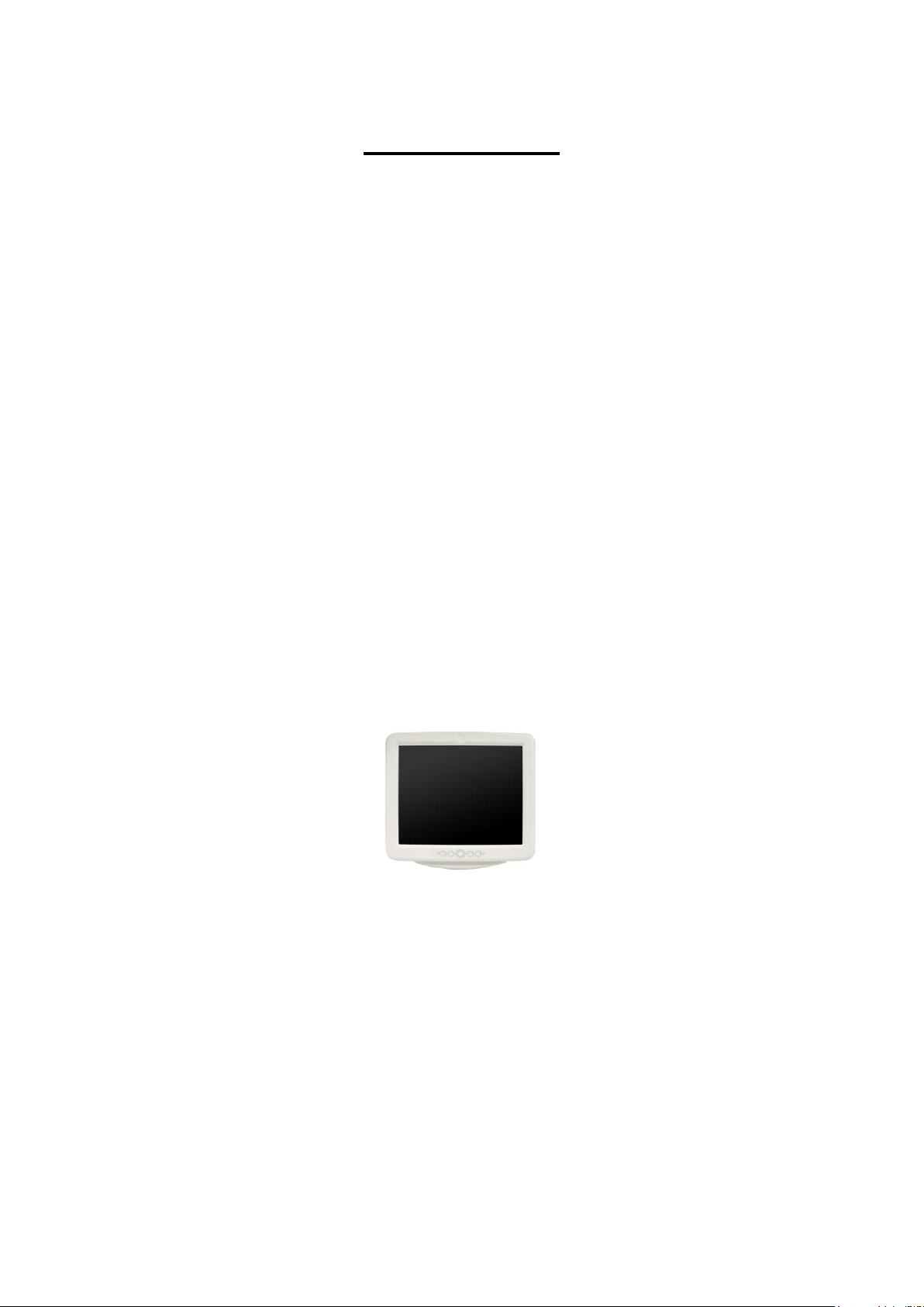
User ’s Manual
iOne-MP17ix (MP176)
All-in-one Medical Panel PC
Copyright© ,2013. All rights reserved
The information in this document is subject to change without notice.
1
Page 2

Table of Contents
I. Safety & Regulatory Notice………………………………………......….……. 3-11
A. FCC Class B……………………………………....................…......……. 3-3
B. Electronic Magnetic Compatibility…………………..........................….. 4-8
C. Safety………………………………………………….........................…. 9-10
D. Intended use………………….......................………………….....…….. 11
II. Product Basic………………………………………............................…........ 12-18
A. Specifications……………………………….....................…..………... 12-14
B. The Packing / Outline / I/O / Control Buttons……......................…….. 15-16
C. Others…………………………………………....................…..…........ 17-18
III. BIOS………………………………………………….................................... 19-27
2
Page 3

I. Safety & Regulatory Notice
A. FCC Class B
This equipment has been tested and found to comply with the limits for a Class B
digital device, pursuant to Part 18 of the FCC Rules.
These limits are designed to provide reasonable protection against harmful
interference when the equipment is operated in a residential environment.
This equipment generates, uses and can radiate radio frequency energy. If not installed
and used in accordance with this user manual, it may cause harmful interference to
radio communications.
Note that even when this equipment is installed and used in accordance with this user
manual, there is still no guarantee that interference will not occur. If this equipment is
believed to be causing harmful interference to radio or television reception, this can
be determined by turning the equipment on and off. If interference is occurring, the
user is encouraged to try to correct the interference by one or more of the following
measures:
Reorient or relocate the receiving antenna
Increase the separation between the equipment and the receiver
Connect the equipment to a power outlet on a circuit different from that to which
the receiver is connected
Consult the dealer or an experienced radio/TV technician for help
Warning:
Any changes or modifications made to the equipment which are not expressly
approved by the relevant standards authority could void your authority to operate the
equipment.
To avoid risk of electric shock, this equipment must only be connected to a supply
main with protective earth.
Do not modify this equipment without authorization of the manufacturer.
3
Page 4
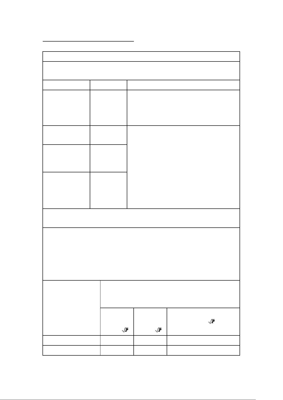
B. Electronic Magnetic Compatibility
Guidance and manufacturer’s declaration – electromagnetic emissions
The iOne-MP176 is intended for use in the electromagnetic environment specified
below. The user should assure the products are used in such an environment.
Emissions test
Compliance
Electromagnetic environment – guidance
RF emissions
CISPR 11
The iOne-MP176 uses RF energy only for its
internal function. Therefore, its RF emissions are
very low and are not likely to cause any
interference in nearby electronic equipment.
RF emissions
CISPR 11
The iOne-MP176 is suitable for use in all
establishments, including domestic
establishments and those directly connected to
the public low-voltage power supply network
that supplies buildings used for domestic
purposes.
Harmonic
emissions
IEC 61000-3-2
Voltage
fluctuations/
flicker emissions
IEC 61000-3-3
Recommended separation distances between
portable and mobile RF communications equipment and the iOne-MP176
The iOne-MP176 is intended for use in an electromagnetic environment in which
radiated RF disturbances are controlled. The user of the iOne-MP176 can help
prevent electromagnetic interference by maintaining a minimum distance between
portable and mobile RF communications equipment (transmitters) and the
iOne-MP176 as recommended below, according to the maximum output power of
the communications equipment.
Rated maximum
output power of
transmitter
W
Separation distance according to frequency of
transmitter
m
150 kHz to
80 MHz
d = 1,2
80 MHz to
800 MHz
d = 1,2
800 MHz to 2,5 GHz
d = 2,3
0,01
0,12
0,12
0,23
0,1
0,38
0,38
0,73
4
Page 5
1
1,2
1,2
2,3
10
3,8
3,8
7,3
100
12
12
23
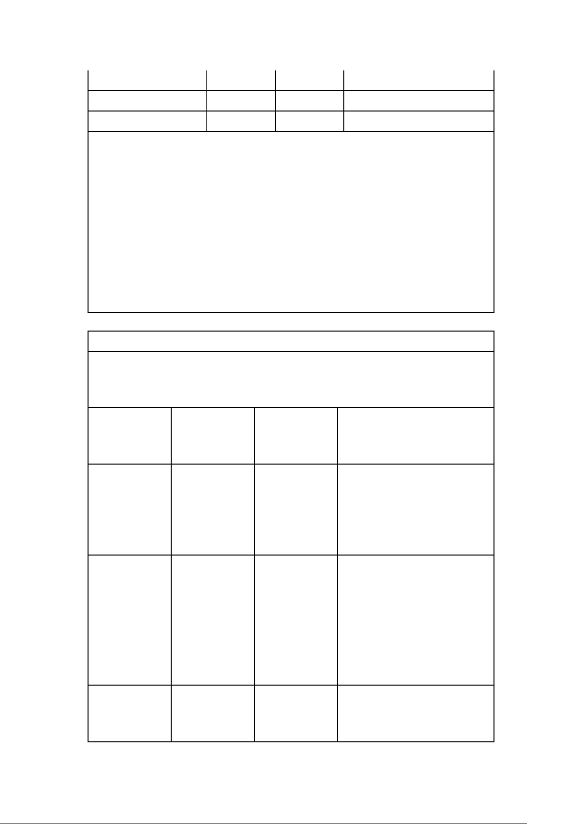
For transmitters rated at a maximum output power not listed above, the
recommended separation distanced in meters (m) can be estimated using the
equation applicable to the frequency of the transmitter, where P is the maximum
output power rating of the transmitter in watts (W) according to the transmitter
manufacturer.
NOTE 1 At 80 MHz and 800 MHz, the separation distance for the higher frequency
range applies.
NOTE 2 These guidelines may not apply in all situations. Electromagnetic
propagation is affected by absorption and reflection from structures, objects and
people.
Guidance and manufacturer’s declaration – electromagnetic immunity
The iOne-MP176 is intended for use in the electromagnetic environment specified
below. The user of the iOne-MP176 should assure that it is used in such an
environment.
Immunity test
IEC 60601
test level
Compliance
level
Electromagnetic environment
–
guidance
Electrostatic
discharge (ESD)
IEC 61000-4-2
6 kV contact
8 kV air
6 kV contact
8 kV air
Floors should be wood, concrete
or ceramic tile. If floors are
covered with synthetic material,
the relative humidity should be
at least 30 %.
Electrical fast
transient/burst
IEC 61000-4-4
2 kV for
power
supply lines
1 kV for
input/output
lines
2 kV for
power
supply lines
1 kV for
input/output
lines
Mains power quality should be
that of a typical commercial or
hospital environment.
Surge
IEC 61000-4-5
1 kV line(s) to
line(s)
1 kV line(s) to
line(s)
Mains power quality should be
that of a typical commercial or
hospital environment.
5
Page 6
2 kV line(s) to
earth
2 kV line(s) to
earth
interruptions and
voltage variations
on power supply
input lines
IEC 61000-4-11
<5 % UT
(>95 % dip in
UT)
for 0,5 cycle
40 % UT
(60 % dip in UT)
for 5 cycles
70 % UT
(30 % dip in UT)
for 25 cycles
<5 % UT
(>95 % dip in
UT)
for 5 sec
<5 % UT
(>95 % dip in
UT)
for 0,5 cycle
40 % UT
(60 % dip in UT)
for 5 cycles
70 % UT
(30 % dip in UT)
for 25 cycles
<5 % UT
(>95 % dip in
UT)
for 5 sec
Mains power quality should be
that of a typical commercial or
hospital environment. If the user
of the iOne-MP176 requires
continued operation during
power
mains interruptions, it is
recommended that the
iOne-MP176 be powered from
an uninterruptible power supply
or a battery.
Power frequency
(50/60 Hz)
magnetic field
IEC 61000-4-8
3 A/m
3 A/m
Power frequency magnetic fields
should be at levels characteristic
of a typical location in a typical
commercial or hospital
environment.
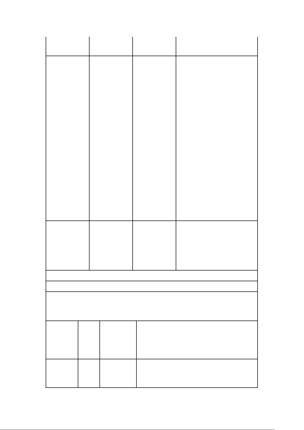
NOTE UT is the a.c. mains voltage prior to application of the test level.
Guidance and manufacturer’s declaration – electromagnetic immunity
The iOne-MP176 is intended for use in the electromagnetic environment specified
below. The user of the iOne-MP176 should assure that it is used in such an
environment.
Immunity
IEC
60601
test
level
Compliance
level
Electromagnetic environment – guidance
Portable and mobile RF communications
equipment should be used no closer to any part
of the iOne-MP176, including cables, than the
6
Page 7
Conducted
RF
IEC
61000-4-6
Radiated RF
IEC
61000-4-3
3 Vrms
150 kHz
to 80
MHz
3 V/m
80 MHz
to 2,5
GHz
Vrms
V/m
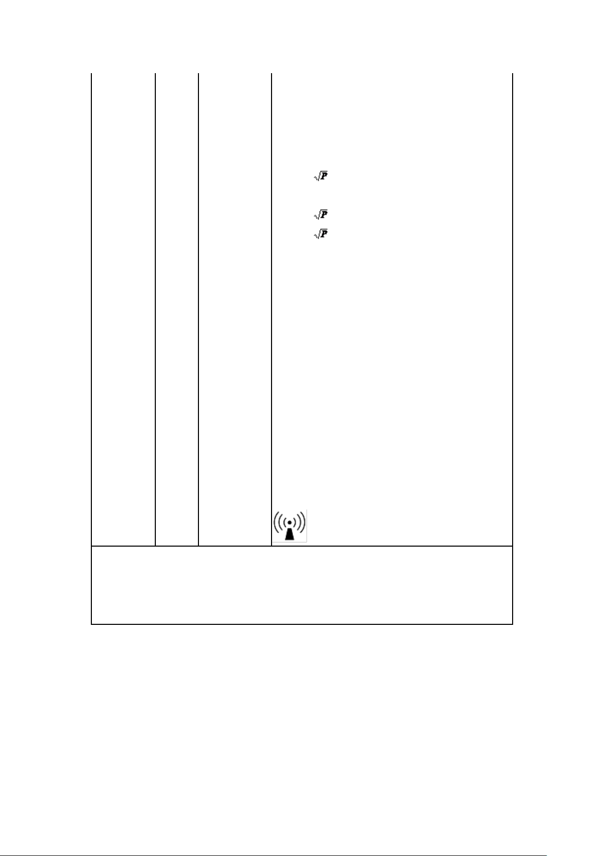
recommended separation distance calculated
from the equation applicable to the frequency of
the transmitter.
Recommended separation distance
d = 1,2
d = 1,2 80 MHz to 800 MHz
d = 2,3 800 MHz to 2,5 GHz
where P is the maximum output power rating of
the transmitter in watts (W) according to the
transmitter manufacturer and d is the
recommended separation distance in meters (m).
Field strengths from fixed RF transmitters, as
determined by an electromagnetic site survey, a
should be less than the compliance level in each
frequency range. b
Interference may occur in the vicinity of
equipment marked with the following symbol:
NOTE 1 At 80 MHz and 800 MHz, the higher frequency range applies.
NOTE 2 These guidelines may not apply in all situations. Electromagnetic
propagation is affected by absorption
and reflection from structures, objects and people.
7
Page 8

a
Field strengths from fixed transmitters, such as base stations for radio
(cellular/cordless) telephones and land mobile radios, amateur radio, AM and FM
radio broadcast and TV broadcast cannot be predicted theoretically with accuracy.
To assess the electromagnetic environment due to fixed RF transmitters, an
electromagnetic site survey should be considered. If the measured field strength in
the location in which the iOne-MP176 used exceeds the applicable RF
compliance level above, the iOne-MP176 should be observed to verify normal
operation. If abnormal performance is observed, additional measures may be
necessary, such as reorienting or relocating the iOne-MP176.
b
Over the frequency range 150 kHz to 80 MHz, field strengths should be less
than V/m.
8
Page 9
C. Safety
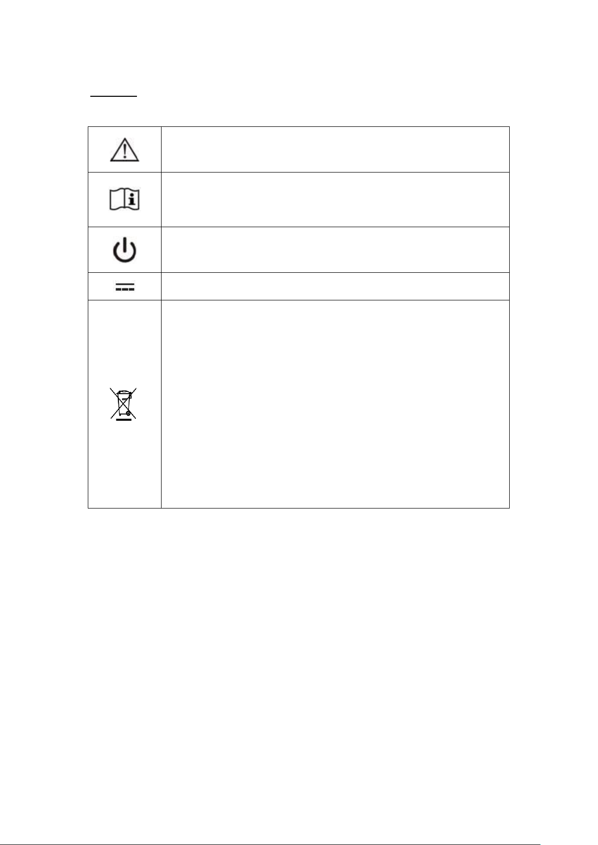
ISO 7000-0434 : Caution, consult ACCOMPANYING DOCUMENTS.
ISO 7000-1641 : Follow operating instructions or Consult instructions
for use.
IEC 60417 -5009 : STAND-BY.
IEC 60417-5031 : Direct current.
EU-wide legislation, as implemented in each Member State, requires
that waste electrical and electronic products carrying the mark (left)
must be disposed of separately from normal household waste. This
includes monitors and electrical accessories, such as signal cables or
power cords. When you need to dispose of your display products,
please follow the guidance of your local authority, or ask the shop
where you purchased the product, or if applicable, follow any
agreements made between yourself.
The mark on electrical and electronic products only applies to the
current European Union Member States.
When networking with electrical devices, the operator is responsible for ensuring that
the resulting system meets the requirements set forth by the following standards:
– EN 60601-1 (IEC 60601-1)
Medical electrical equipment
Part 1: General requirements for safety
– EN 60601-1-1 (IEC 60601-1-1)
Medical electrical equipment
Part 1-1: General requirements for safety
Collateral standard: Safety requirements for
Medical electrical systems
9
Page 10
– EN 60601-1-2 (IEC 60601-1-2)
Medical electrical equipment
Part 1-2: General requirements for safety
Collateral standard: Electromagnetic compatibility; Requirements and tests
Accessory equipment connected to the analog
and digital interfaces must be in compliance
with the respective nationally harmonized IEC
standards (i.e. IEC 60950 for data processing
equipment, IEC 60065 for video equipment,
IEC 61010-1 for laboratory equipment, and
IEC 60601-1 for medical equipment.)
Furthermore all configurations shall comply with the system standard IEC 60601-1-1.
Everybody who connects additional equipment to the signal input part or signal output
part configures a medical system, and is therefore, responsible that the system
complies with the requirements of the system standard IEC 60601-1-1. The unit is for
exclusive interconnection with IEC 60601-1 certified equipment in the patient
environment and IEC 60XXX certified equipment outside of the patient environment.
If in doubt, consult the technical services department or your local representative.
10
Page 11

D. Intended Use
The iOne-MP17ix is designed to serve as a medical PC for general purpose usage in
the hospital environment and for diagnosis. It could be used for Surgical, Radiology,
PACS (Picture Archiving Communication Systems), LIS (Lab Information Systems)
and Electronic Medical Record purpose.
It shall not be used in life-supporting systems.
Warning: Critical diagnostic decision must not be based solely on images displayed
by this device.
Caution: Use suitable mounting apparatus to avoid risk of injury.
The sound pressure level at the operator’s position according to IEC 704-1:1982 is no
more than 70dB (A).
A. Grounding reliability can only be achieved when the equipment is connected to an equivalent
receptacle marked “Hospital Only” or “Hospital Grade”.
B. Use a power cord that matches the voltage of the power outlet, which has been
approved and complies with the safety standard of your particular country.
C. Caution: This power adapter “Sinpro MPU101-105” is a forming part of this
medical PC.
11
Page 12
II. Product Basic
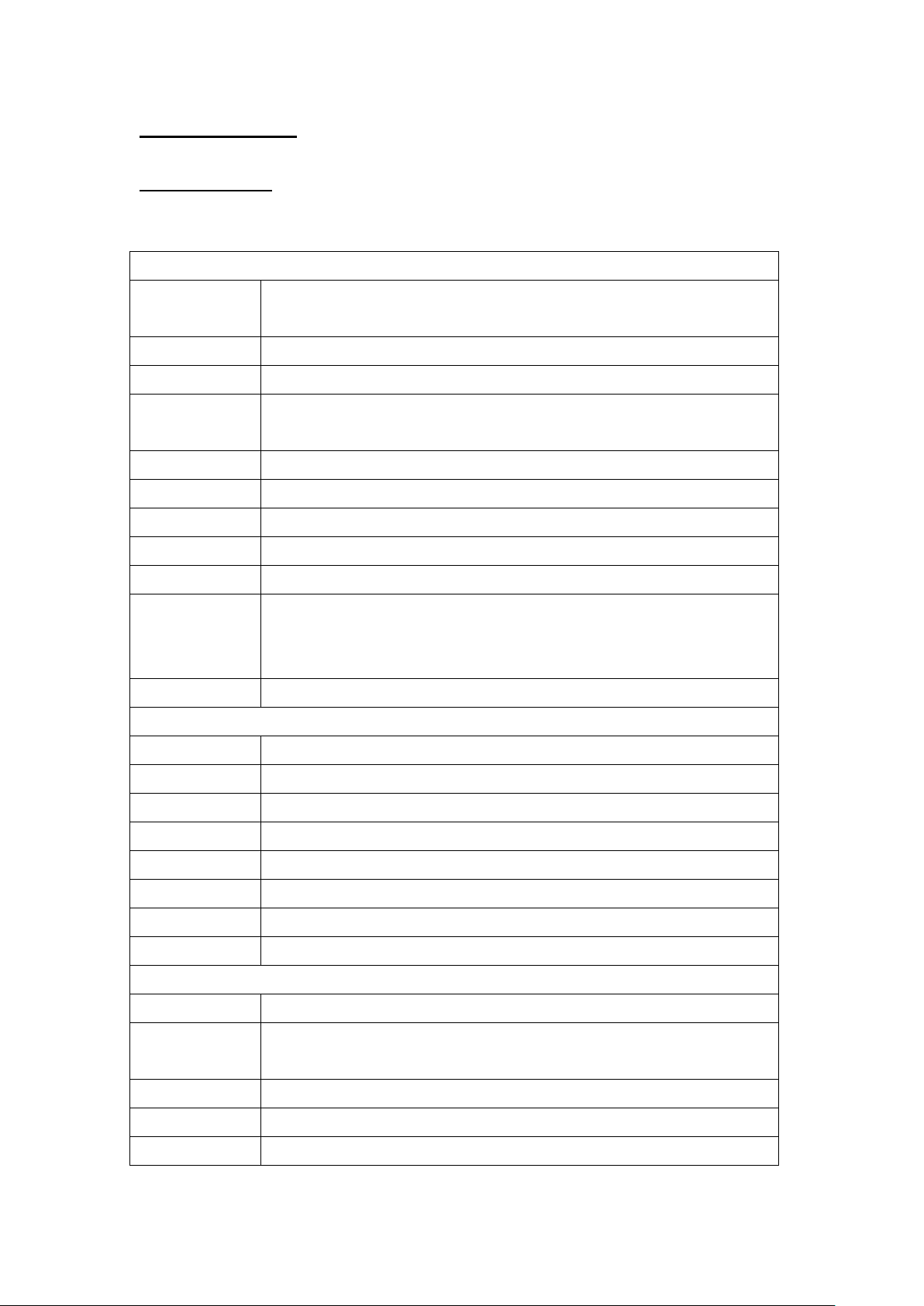
Main System
CPU
. Support Intel Sandy Bridge & Ivy Bridge mobile CPU w/
PGA988 package, 35W TDP (max.) and integrated graphics
Chipset
Intel BD82HM65 PCH
Graphics
. Intel HD Graphics HD 3000 or Intel HD Graphics HD 4000
Memory
8GB maximum, x 2 DDR3 SODIMM, 1066/1333MHz,
2GB/4GB/8GB
Serial ATA
SATA2 x 2, 300MB/s transfer rate
USB
x 7 (socket), USB 2.0 (x 4 external, x 3 internal)
COM
x 6 (x 2 external, x 4 internal)
Audio
Realtek ALC262 audio codec, 2+2 watts amplifier
LAN
Marvell 88E8071 Gigabit Ethernet x 2
BIOS
. AMI BIOS, 4M EEPROM
. RTC wake up/Wake on LAN/Power on after power failure/
PnP/ACPI
Speaker
2 watts x 2 (front bottom)
LCD Panel
Size
17“ 5:4
Resolution
1280 x 1024
Brightness
380 nits
Contrast
1000:1
Color numbers
16.7M (6-bit x 3 + FRC)
Viewing angle
170 (H) / 160 (V)
Response time
5 ms (R + F)
Backlight
CCFL, 50,000 hours life time
Touch Panel
Technology
Resistive touch, 5-wire
Light
transmittance
81 ± 3%
Hardness
≧ 3H
Touch stylus
No limitation
Resolution
4096 x 4096
A. Specifications
12
Page 13
13
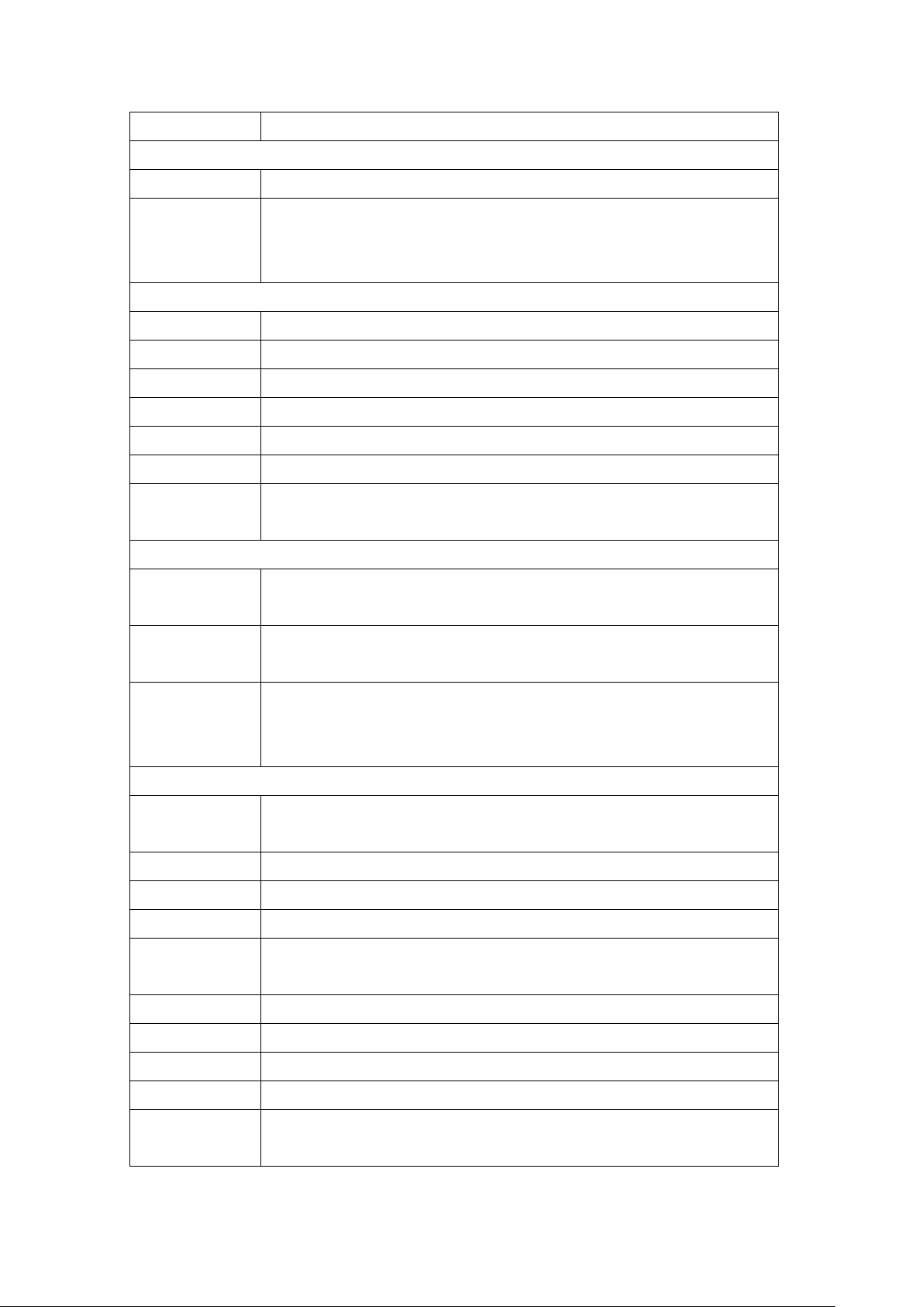
Life time
35 million activations
Storage & Expansion
HDD
2.5” SATA HDD drive bay x 1 + anti-vibration kit
Expansion slot
. PCI-E (x16) x 1 or PCI x 1 (optional)
. Card size: 100 x 155 x 18/0.5 mm or 68 x 220 x 18/0.5 mm
. Mini PCIe x 2 (52 pin card-edge type)
I/O & Control Keys
USB
USB 2.0 x 4
COM
DB-9 x 2 (RS232, RS232/422/485)
LAN
RJ-45 x 2, Gigabit
Video-out
DVI-I x 1
Audio
Line-out, Microphone-in (3.5 mm phone-jack)
Power input
DC-in x 1, 6V~32V
Control keys
. Front side, membrane type
. Power on/off, Brightness, Audio volume
Power
Power adaptor
External, 100 watts, 90~264V AC in, 12V DC out, medical grade,
(Sinpro MPU101-105)
Power
consumption
. 75 watts (typical, without any add-ons)
Internal
battery
(optional)
. Rechargeable Lithium-Ion, 2S2P, 29.2Wh (avg.) / 27.74Wh
(min.), for 20-25 minutes operating (approx.)
. Charge time: 2 hours (system off), 3.5 hours (system on)
Mechanical & Environmental
Housing
. Plastic front bezel, rear cover and I/O cover w/ antibacterial
Coating / White color
IP rating
IP65 – front side
Cooling
Variable speed smart fan design, < 30 dB (typical)
Mounting
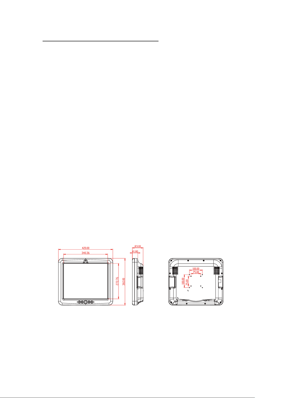
VESA 75 x 75 / 100 x 100 mm
Kensington
lock
Yes, x 1 at bottom
Dimension
420 x 360 x 83 mm (W x H x D, w/o stand)
Weight (net)
6.5 Kg (approximate, w/o power adaptor)
Temperature
. Operating – 0°C~40°C . Storage – -20°C~60°C
Humidity
Operating & storage – 10%~90%, non-condensing
Regulatory
. FCC-B, cUL, CE, VCCI
. Medical 60601-1 3rd edition
Page 14

(EN 60601-1:2006, ANSI/AAMI
ES60601-1:2005, CAN/CSA C22.2 No. 60601-1:08)
Options
Options
. WLAN – mini PCIe module w/ internal antenna x 2
. Bluetooth 2.1 (USB)
. Battery pack
. Power adaptor w/ 2.4m or 3.6m DC cable
. Desktop stand
14
Page 15
B. The Packing / Outline / I/O / Control Buttons
Basic packing list --
. The medical PC: iOne-MP17ix
. Power adaptor (Sinpro MPU101-105)
. AC power cord
. Touch stylus pen
. DVD title (with drivers & user’s manual)
. User’s manual
. Screws (for rear cover VESA mounting)
Note: The contents may vary due to different options or configuration.
Outline dimension –
15
Page 16
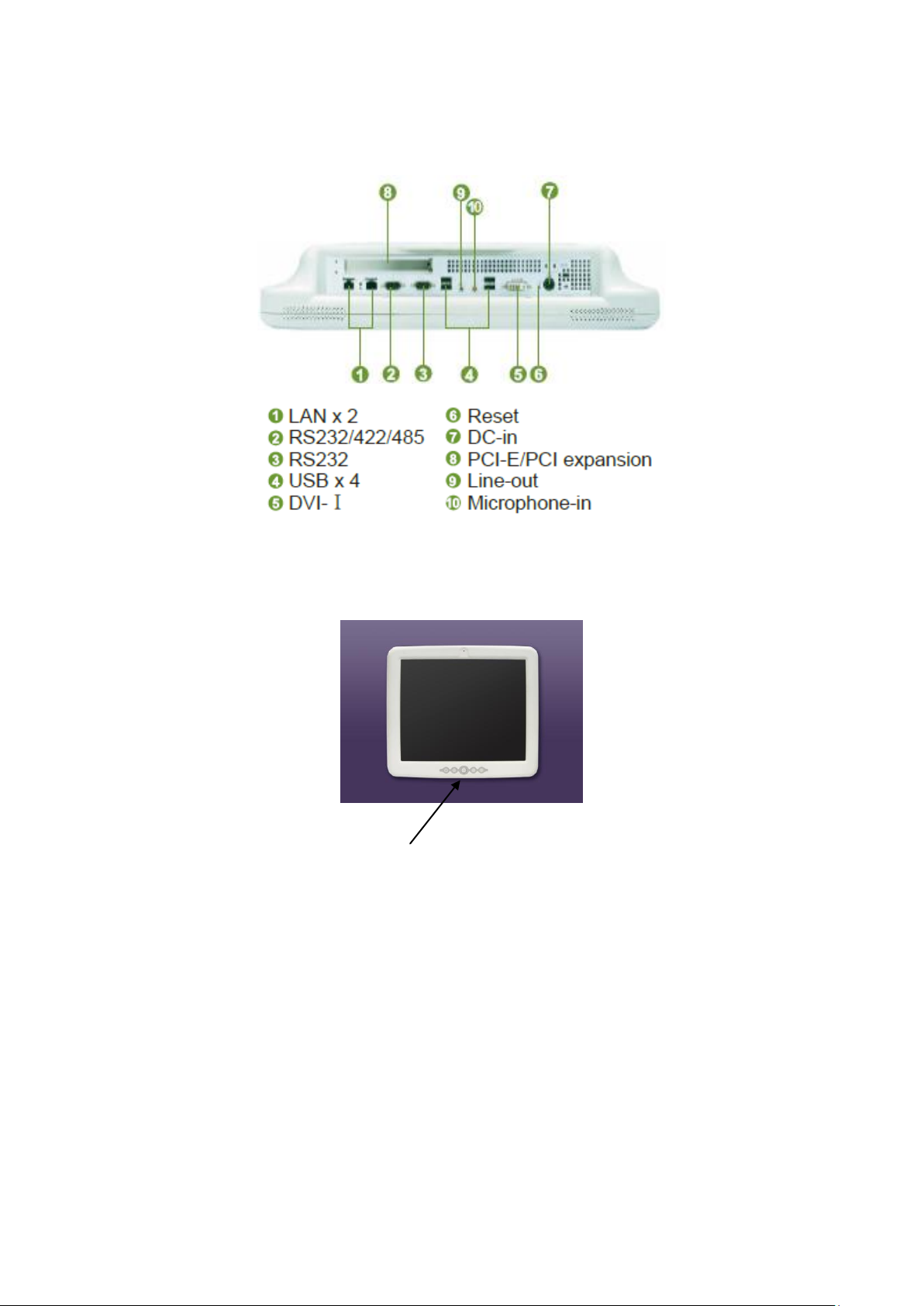
The I/O interface (basic configuration)
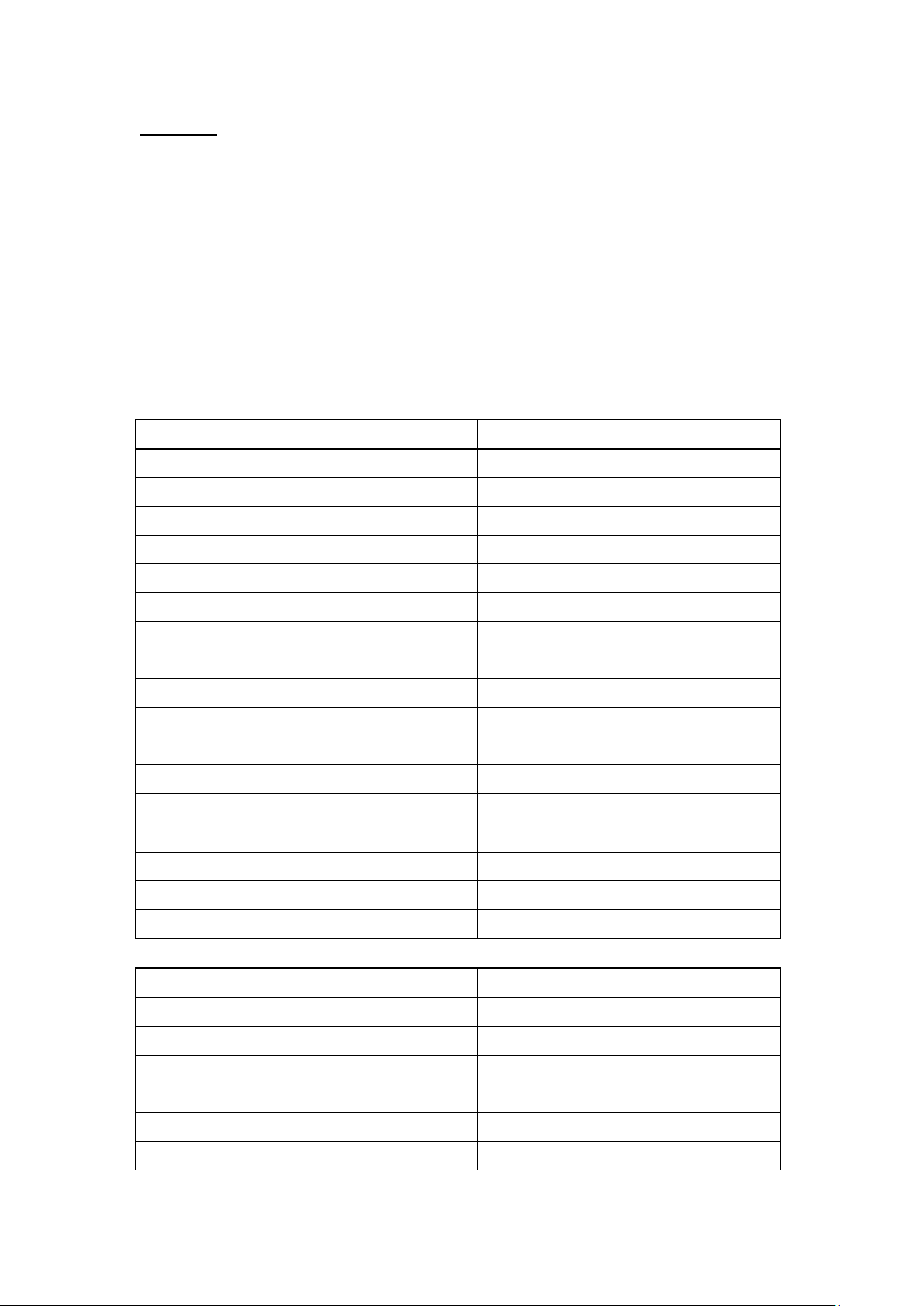
The control buttons
- From left to right -
. Brightness (-)
. Brightness (+)
. Power on/off
. Speaker volume (-)
. Speaker volume (+)
16
Page 17
C. Others
Chemical
Touch panel
40% Sodium Hydroxid
Damage
Acetone
OK
Carbitol Acetate
OK
Cellosolve Acetate
OK
Ethanol / Alcohol
OK
Methylene Chloride
OK
Hydrochloric Acid - 6%
OK
Hexane
OK
Isopropanol (Isopropyl Alcohol)/Propanol
OK
Methyl Ethyl Ketone
OK
Heptane
OK
Toluene
Damage
Turpentine
OK
Vm & P Naptha
OK
Bleach (Sodium Hypochlorite,NaOCI)
Damage
Benzyl alcohol
OK
Hydrogen peroxide
Damage
Chemical
Plastic housing
40% Sodium Hydroxid
Damage
Acetone
Damage
Carbitol Acetate
Damage
Cellosolve Acetate
Damage
Ethanol / Alcohol
500g load with 95% Alcohol--> OK
Methylene Chloride
Damage
To clean or disinfect the system
To clean or disinfect the system, to avoid any damage to the touch panel and the
plastic housing, please check below chemical resistance table to ensure you
disinfectant does not contain harmful ingredients.
We suggest to use Ethanol but do check with the personal who is responsible for
disinfecting.
17
Page 18
Hydrochloric Acid - 6%
Damage
Hexane
Damage
Isopropanol (Isopropyl Alcohol)/Propanol
Damage
Methyl Ethyl Ketone
Damage
Heptane
Damage
Toluene
500g load with 5% Cresol --> OK
Turpentine
Damage
Vm & P Naptha
Damage
Bleach (Sodium Hypochlorite,NaOCI)
500g load with 10% Bleach--> OK
Benzyl alcohol
Damage
Hydrogen peroxide
Damage
Battery cell type
Lithium-Ion rechargeable battery cell (2000mAh/cell)
Configuration
2S2P
Typical capacity
4000mAh (for two cells)
Minimum capacity
3800mAh (for two cells)
Nominal voltage
7.3 V (average)
Energy
29.2 Wh (typical) / 27.74 Wh (minimum)
Charge voltage
8.4 V (typical)
Charge time
.System on (1A): 200 minutes
.System off (2A): 120 minutes
Battery life
Discharge (> 10 minutes) for 300 times, < 70% capacity left
The internal battery (optional)
For those systems installed with internal battery, below is the specifications.
During the transportation, we suggest you to disable battery --
Power off the system
Disconnect the DC power (or AC power cord)
Press the “speaker volume (+)” button for 10 seconds
Next time when you connect the AC power and power on the system, the battery will
be enabled automatically.
18
Page 19
III. BIOS
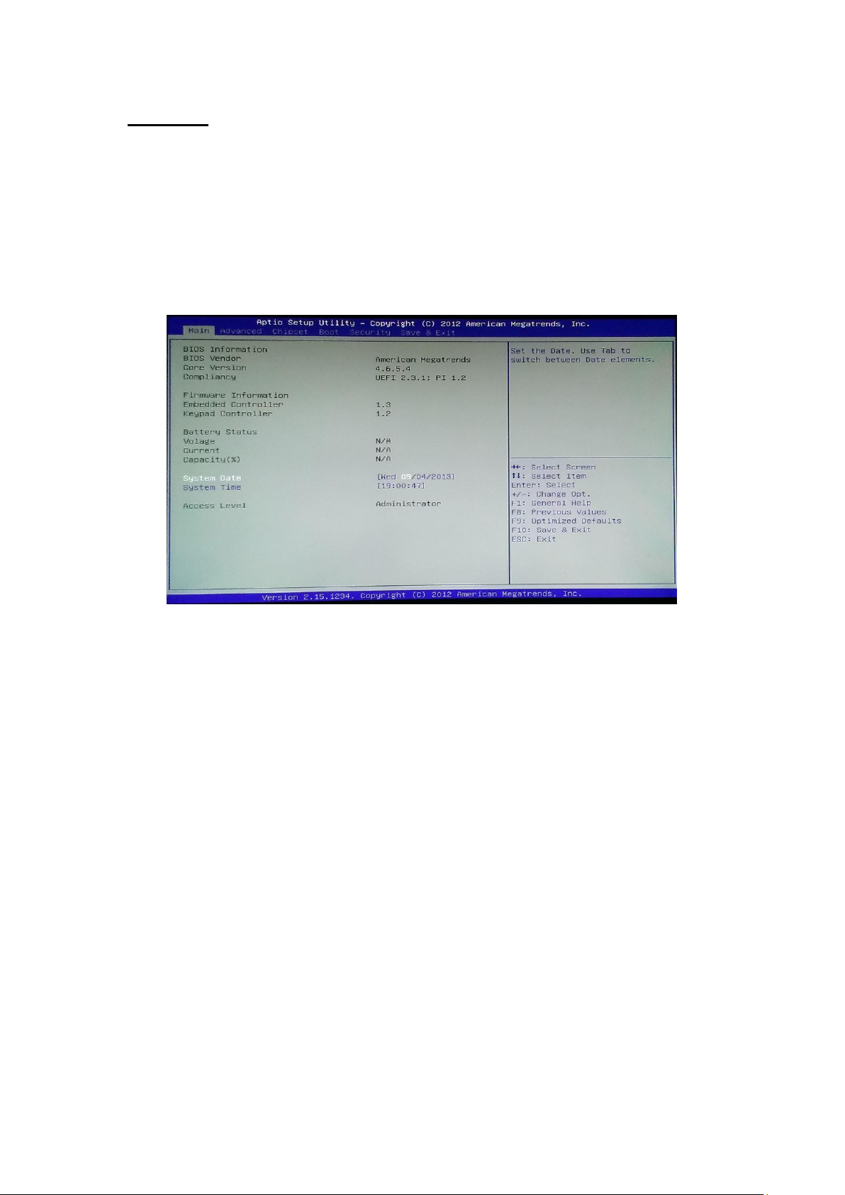
Immediately after powering on the system, during the POST (Power On Self Test)
stage, press the <Del> key to enter the BIOS setup utility program.
Follow the menu & the keys instruction to modify the BIOS configuration & settings.
Main --
19
Page 20
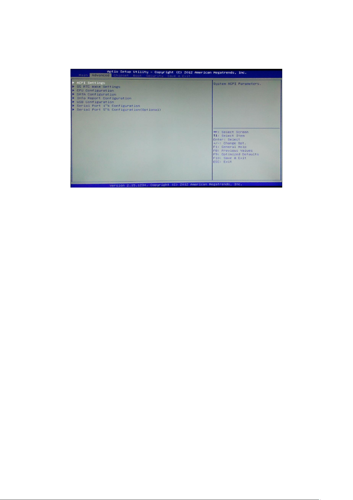
Advanced --
ACPI Settings
Enable ACPI Auto Configuration
Enables or Disables BIOS ACPI Auto Configuration.
Enable Hibernation
Enables or Disables System ability to Hibernate (OS/S4 Sleep State). This option
may be not effective with some OS.
ACPI Sleep State
Select the highest ACPI sleep state the system will enter, when the SUSPEND
button is pressed.
Lock Legacy Resources
Enables or Disables Lock of Legacy Resources.
S3 Video Repost
Enables or Disables S3 Video Repost.
S5 RTC Wake Settings
Wake System with Fixed Time
Enables or disables system wake on alarm event. When enabled, the system will
wake on the time specified.
Wake system with Dynamic Time
Enables or disables system wake on alarm event. When enabled, the system will
wake on the current time+Increase minute(s).
CPU Configuration
20
Page 21

Hyper-Threading
Enabled for Windows XP and Linux (OS optimized for Hyper-Threading
Technology) and Disabled for other OS (OS optimized for Hyper-Threading
Technology)
Active Processor Cores
Number of cores to enable in each processor package.
Limit CPUID Maximum
When CPUID instruction is executed, newer CPU may return a value greater
than 3 which causes certain problem with specific operating systems. Enabling
"CPUID Maximum Value Limit" in the CPU configuration of BIOS setup menu
will limit the returned value to 3 and less to get rid of the problem. The problem
is not seen with newer Windows series operating systems so the default is set to
disabled for it.
Execute Disable Bit
XD can prevent certain classes of malicious buffer overflow attacks when
combined with a supporting OS (Windows Server 2003 SP1, Windows XP SP2,
SuSE Linux 9.2, RedHat Enterprise 3 Update 3.)
Intel Virtualization Technology
When enabled, a VMM can utilize the additional hardware capabilities provided
by Vanderpool Technology
Hardware Prefetcher
To turn on/off the Mid Level Cache (L2) streamer prefetcher.
Adjacent Cache Line Prefetch
To turn on/off prefetching of adjacent cache lines.
TCC Activation offset
Offset from the factory TCC activation temperature.
Primary Plane Current value
The Maximum instantaneous current allow for Primary Plane.
Secondary Plane Current value
The Maximum instantaneous current allow for Secondary Plane.
SATA Configuration
SATA Controller(s)
Enable or disable SATA device.
SATA Mode Selection
Select a configuration for SATA controller.
SATA Test Mode
21
Page 22

This is typically required when the user wants to examine the physical
parameters of the host adapters transmit PHY (eg examine the ‘eye’ on a scope or
similar).
IDE Legacy / Native Mode Selection.
IDE Legacy / Native Mode Selection.
Info Report Configuration
System configration information report. It includes Post report/Error message
report/Summary report
USB Configuration
Legacy USB Support
Enables Legacy USB support. AUTO option disables legacy support if no USB
devices are connected. DISABLE option will keep USB devices available only
for EFI applications
EHCI Hand-off
This is a workaround for 0Ses without EHCI hand-off support. The EHCI
ownership change should be claimed by EHCI driver.
USB Mass Storage Driver Support
Enable/Disable USB Mass Storage Driver Support.
USB transfer time-out
The time-out value for Control, Bulk, and Interrupt transfers.
Device reset time-out
USB mass storage device Start Unit command time-out.
Device power-up delay
Maximum time the device will take before it properly reports itself to the HOST
Controller.
‘Auto’ uses default value: for a Root port it is 100 ms, for a Hub port the delay is
taken from Hub descriptor.
Serial Port 1~4 Configuration
Serial Port 1 Configuration
Set Parameters of Serial Port 1.
Serial Port 2 Configuration
Set Parameters of Serial Port 2.
Serial Port 3 Configuration
Set Parameters of Serial Port 3.
Serial Port 4 Configuration
22
Page 23

Set Parameters of Serial Port 4.
Serial Port 5~6 Configuration(Optional)
Serial Port 5 Configuration
Set Parameters of Serial Port 5.
Serial Port 6 Configuration
Set Parameters of Serial Port 6.
23
Page 24
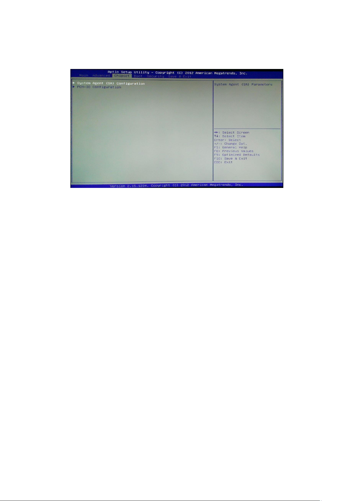
Chipset --
System Agent (SA)/PCH-IO Configuration
This screen provides information on System Agent and PCH parameters.
24
Page 25
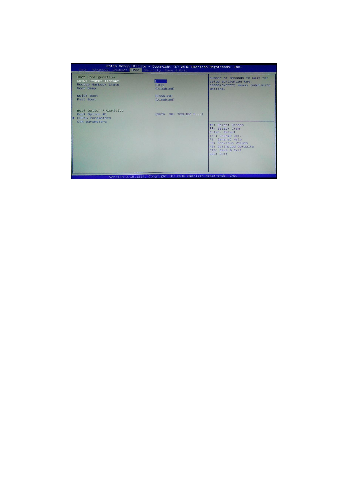
Boot --
Setup Prompt Timeout
Number of seconds to wait for setup activation key. 65535(0xFFFF) means
indefinite waiting.
Bootup Numlock State
Selects the keyboard NumLock state.
Boot Beep
Enables or disables boot status beep
Quiet Boot
Allows you to determine whether to display the Logo at system startup. Disabled
displays normal POST message.
Fast Boot
Enables or disables the quick boot function to speed up the system boot-up process
to shorten the waiting time for entering the operating system and to deliver greater
efficiency for daily use.
CSM16 Parameters
Enable/Disable option ROM execution settings, etc.
CSM parameters
Option ROM execution, boot options filter, etc.
25
Page 26
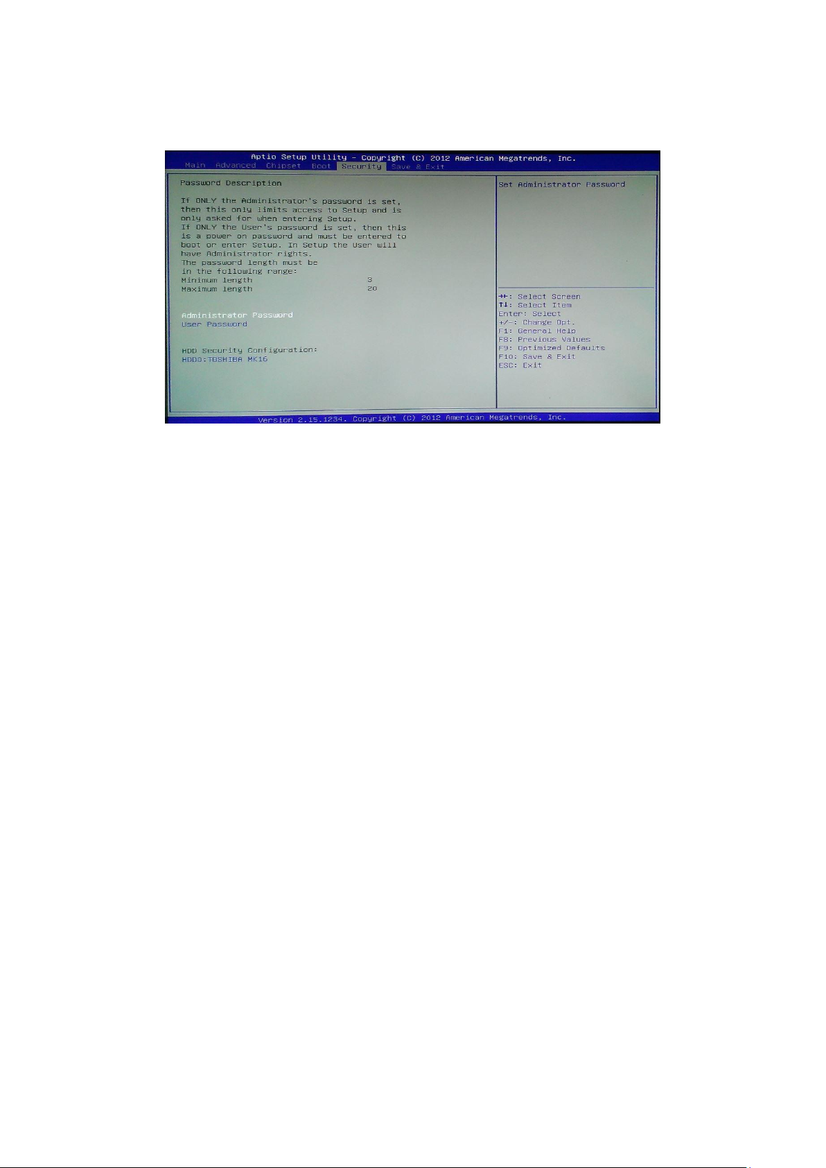
Security –
Enables or disables the security chip. It is recommended that you use this function
with the Administrator/User password.
26
Page 27
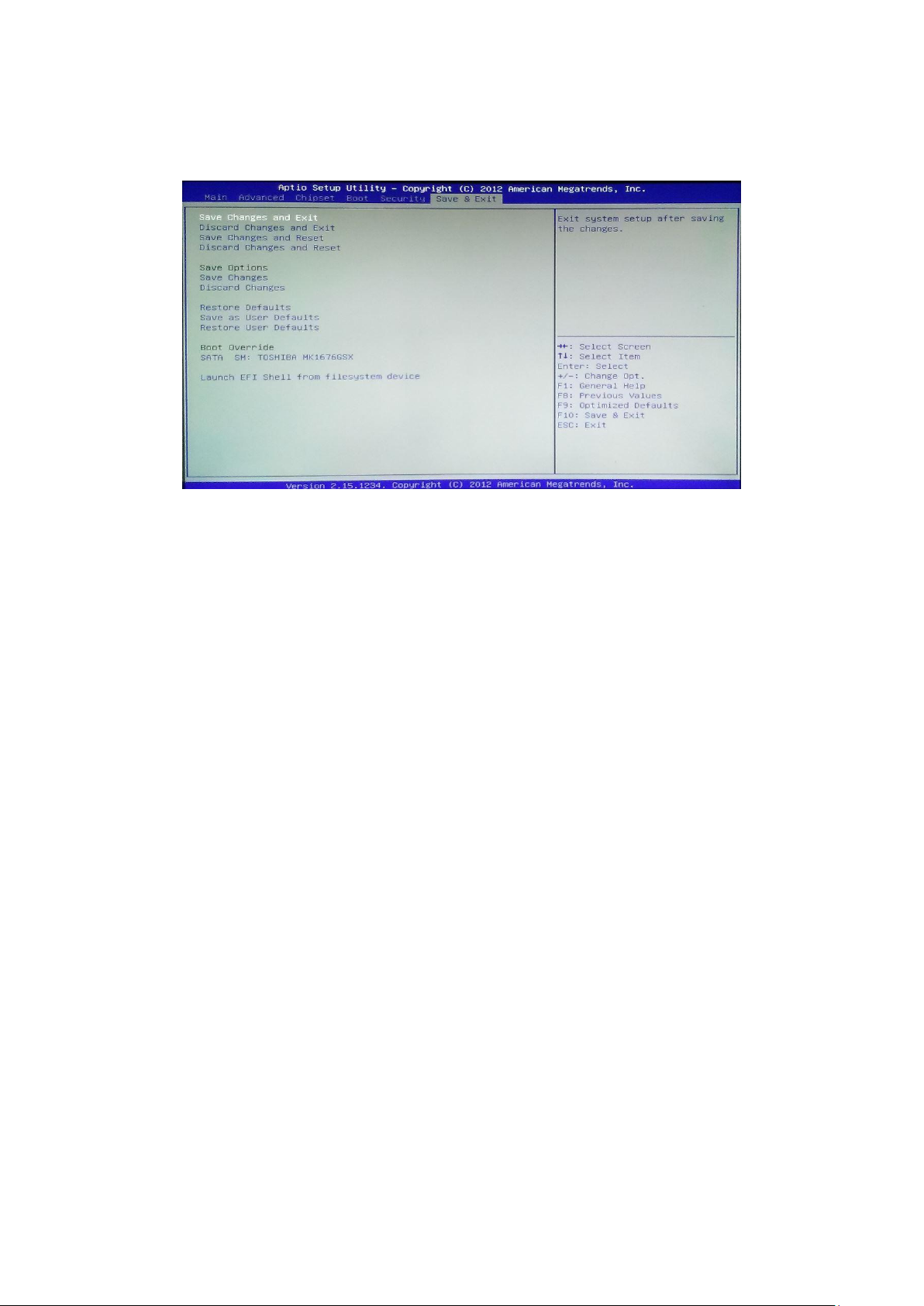
Save & Exit –
Save Changes and Exit
Exit system setup after saving the changes.
Discard Changes and Exit
Exit system setup without saving any changes.
Save Changes and Reset
Reset the system after saving the changes.
Discard Changes and Reset
Reset system setup without saving the changes.
Save Changes
Save the changes done so far to any of setup options.
Discard Changes
Discard the changes done so far to any of setup options.
Restore Defaults
Restore/load default values for all the setup options.
Save as User Defaults
Save the changes done so far as User Defaults.
Restore User Defaults
Restore the User Defaults to all the setup options.
Launch EFI Shell From filesystem device
Attempts to Launch EFI Shell application (Shellx64.efi) from one of the available
filesystem devices.
27
 Loading...