


LCD-PC
r
C22
Ser
es
Use
Gu
de

FCC-B
e
n
2
m
A
A
A
e
o
y
d
b
e
o
n
n
e
b
n
a
c
c
h
r
a
0
m
a
e
p
s
o
s
t
e
u
n
o
e
a
r
l
o
e
n
p
p
o
e
u
e
s
n
a
h
r
e
o
a
o
h
t
t
o
y
m
n
f
e
e
o
t
n
o
the limit
designe
installat
not inst
interfer
will not
to radio
on, the
measur
I
Radio F
for a clas
d to provid
on. This e
lled and u
nce to rad
ccur in a
or televisi
ser is enc
s listed b
eorient or
crease th
onnect th
r
ceiver is
onsult the
equenc
B digital
reasona
uipment g
ed in acc
o commun
articular i
n receptio
uraged to
low.
relocate th
distance
equipme
onnected.
dealer or
Interfer
This equi
evice, pur
le protecti
nerates u
rdance wi
ications. H
stallation.
, which ca
try to corr
receiving
etween th
t into an o
n experie
nce Stat
ment has
uant to p
n against
es and ca
h the instr
owever, th
f this equi
n be deter
ct the inte
antenna.
e equipme
tlet on a c
ced radio/
ment
been teste
rt 15 of th
harmful int
radiate r
ction man
re is no g
ment doe
ined by t
rference b
nt and rec
ircuit differ
elevision t
d and foun
FCC rule
erference i
dio freque
ual, may c
arantee t
cause ha
rning the
one or m
iver.
nt from th
chnician f
d to compl
. These li
n a reside
cy energy
use harm
at interfer
mful interf
quipment
re of the
t to which
r help.
with
its are
tial
and, if
ul
nce
rence
ff and
the
Notice
Notice
Trade
ll trad
Intel® i
Windo
ward
MI® is
The
resp
equi
Shiel
to co
arks
marks are
a register
s® 7/Vist
is a regist
a register
hanges or
nsible for
ment.
ed interfa
ply with t
the prope
d tradem
/XP/NT/20
red trade
d tradem
modificati
omplianc
e cables
e emissio
ties of thei
rks of Inte
0/98/95 a
ark of Ph
rk of Amer
ns not ex
could voi
nd A.C. p
n limits.
respectiv
Corporati
e register
enix Tech
ican Mega
ressly ap
the user'
wer cord, i
owners.
n.
d tradema
nologies L
rends Inc
roved by t
authority
f any, mus
ks of Micr
d.
e party
o operate
be used i
soft Corp
he
order
ration.
i

Safe
Al
e
l
Al
Al
h
o
o
W
AN
e
w
a
n
t
e
n
e
w
n
e
e
s
x
c
a
n
i
p
t
s
s
s
s
v
c
P
o
m
s
u
a
e
N
s
t
a
r
e
e
c
c
m
e
o
t
t
h
r
m
o
d
p
a
0
y
b
b
E
r
s
t
e
o
e
e
g
d
l
Y
c
o
a
u
o
n
a
O
E
e
t
u
o
i
n
n
a
W
ty Instructions
1.
2. K
3. L
4. T
5. C
6. P
7.
8.
9. N
10. D
11. T
12. D
13.
14. If
15. D
ways read
y this equi
e opening
e
uipment f
b
fore conn
ace the po
pl
ways unpl
l cautions
s
ock.
c
nnected t
e Optical
c
ntrols or a
p
ohibited.
hen installi
m
etal shield
C
G
rounding o
any of the
s
rvice pers
odification
m
ep this eq
nfirm the
ce anythi
ver pour
not disa
not touc
ble distrib
SI/NF PA
The po
Liquid h
The equ
The equ
the Use
The equ
The equ
not atte
the safety
uipment a
pment on
s on the e
om overhe
oltage of
cting the
wer cord i
g over th
g the Po
nd warnin
ny liquid i
le the prot
a ground
torage de
justment
the Laser
ng the coa
is reliably
ution syste
70, the N
Outer Co
ollowing s
nnel:
er cord or
s penetra
pment ha
pment ha
's Guide.
pment ha
pment ha
pt to remo
should be
instruction
ay from h
reliable fl
closure ar
ating. DO
he power
quipment
such a w
power co
er Cord b
gs on the
to the ope
ctive grou
d main so
vices are
or perfor
lens insid
ial cable t
onnected
ms should
tional Elec
ductive S
tuations a
lug is da
ed into the
been exp
not worke
been dro
obvious si
e or upgr
onducted
carefully.
midity.
t surface
for air co
OT COV
ource and
o the pow
y that it c
d.
fore inserti
quipment
ning. Thi
nding pin f
ket/outlet.
lassified a
ance of pr
the optica
the TV T
o a protec
be ground
rical Code
ield of a C
ise, have t
aged.
equipmen
sed to mo
well or y
ped and d
gns of bre
de any co
by service
efore sett
vection h
R THE O
adjust ac
r inlet.
nnot be st
ng any ad
hould be
will caus
om the pl
Class 1
ocedures
l storage d
ner, it is n
ive earthin
d (earthe
(NEC ), in
oaxial Cab
he equipm
.
isture.
u cannot
maged.
kage.
ponent b
personnel
ng it up.
nce prote
ENINGS.
ordingly to
pped on.
-on card
oted.
damage
g. The eq
aser prod
ther than t
rive.
ecessary t
system o
) in accord
particular,
le.
nt checke
et it worki
yourself,
t the
110/220V
Do not
r module.
nd/or elec
uipment m
cts. Use
hose spec
ensure th
f the buildi
ance with
Section 82
d by autho
g accordi
ny install
rical
st be
f
fied is
at the
g.
0.93,
rized
g to
tion or
DO NO
STORA
EQUIP
CAUTI
same o
LEAVE
E TEMP
ENT.
N: Dange
equivalen
HIS EQUI
RATURE
of explosi
type reco
MENT IN
ABOVE 5
n if batter
mended
AN UNCO
° C (122°
is incorre
y the ma
ii
DITIONE
). IT MA
ctly replac
ufacturer.
D ENVIR
DAMAG
d. Replac
NMENT
THE
only with
ITH A
the

WEEE
e
p
t
a
e
c
e
v
n
e
n
e
r
e
r
e
u
e
o
d
m
a
s
m
y
p
m
n
c
a
e
e
t
h
n
e
u
c
a
S
r
e
r
o
f
a
n
d
e
h
U
o
d
s
l
n
n
w
i
E
s
u
i
a
b
d
u
d
p
e
Stateme
t
(Waste
The W
retailer
sister D
Directiv
design
2005.
the cos
percent
Instructi
The sy
product
dispose
recyclin
recyclin
resourc
environ
for recy
or wher
Electrical
EE directi
and impo
rective, R
by banni
hase. Th
U-based
s of recov
ges per t
ons for dis
bol show
must not b
of their wa
of waste
of your
s and ens
ent. For
ling, plea
you purc
nd Electro
e places a
ters to tak
HS (Rest
g the pres
WEEE Di
anufactur
ry from m
e WEEE r
osal of W
below is
e dispose
ste equip
electrical
aste equip
ure that it i
ore infor
e contact
ased the
ic Equip
n obligatio
-back ele
iction of H
nce of sp
ective cov
rs, distribu
nicipal col
quiremen
EE by Us
n the prod
of with ot
ent by han
nd electro
ment at th
recycled
ation abo
our local
roduct.
ent)
on EU-b
tronics pr
zardous
cific haza
rs product
tors, retail
ection poi
s.
ers in the
ct or on it
er waste.
ding it ove
ic equipm
time of di
in a mann
t where y
ity office,
sed manu
ducts at th
ubstances
dous subs
s imported
rs and im
ts, reuse,
uropean
packagin
Instead, it
to a desig
nt. The s
posal will
r that prot
u can dro
our house
acturers,
e end of th
) complim
ances in t
into the E
orters are
nd recycli
nion
, which in
s the user’
nated colle
parate co
help to co
cts huma
off your
old waste
istributors,
eir useful l
nts the W
e product
as of Aug
bliged to f
ng of spec
icates th
responsi
ction point
lection an
serve nat
health an
aste equi
disposal s
fe. A
EE
at the
st 13,
inance
fied
t this
ility to
for the
ral
the
ment
rvice
iii

TABLE OF CONTENTS
FCC-B Radio Frequency Interference Statement ...................................................................... i
Trademarks ................................................................................................................................... i
Safety Instructions ...................................................................................................................... ii
WEEE Statement ........................................................................................................................ iii
Introduction ................................................................................................................................. 1
LCD-PC C22 Series Specifications ............................................................................................ 1
Processor Support .................................................................................................................. 1
Motherboard Core Logic ...................................................................................................... .. 1
Memory Support ...................................................................................................................... 1
Networking ............................................................................................................................... 1
Audio ......................................................................................................................................... 1
Hard Disk Drive ........................................................................................................................ 2
Mounting ................................................................................................................................... 2
LCD Panel ................................................................................................................................. 2
Expansion Slots ....................................................................................................................... 2
Front Lower Right Bezel ......................................................................................................... 2
Right Side Bezel ....................................................................................................................... 2
Left Side Bezel ......................................................................................................................... 2
Bottom I/O Panel ..................................................................................................................... 3
Power Supply ........................................................................................................................... 3
Dimensions .............................................................................................................................. 3
Power Management .................................................................................................................... 8
Waking the System Up .......................................................................................................... 10
Energy Saving Tips ............................................................................................................... 10
C22 Series Overview……...…………..…………………………………...…………………………11
On Screen Display Buttons………………………………………………………………………….14
On Screen Display Usage ..................................................................................................... 15
System Assembly ..................................................................................................................... 20
Necessary Tools ...................................................................................................................
Orientation of Key Parts ........................................................................................................ 21
C22 Series Disassembly ....................................................................................................... 22
20
Installing the CPU .................................................................................................................. 24
Installing the CPU Heat Sink ................................................................................................. 25
iv

Installing the Memory Module DDR3 SO-DIMM .................................................................. 26
Installing the Hard Disk Drive ............................................................................................... 27
Installing the Optical Disk Drive ........................................................................................... 28
Installing the Mini-PCIe Card (Optional) .............................................................................. 30
Installing the Cover ............................................................................................................... 31
Figures
Figure 1: Front View with Optional Webcam………….…………………………….....……..……11
Figure 2: Left side view with Optical Drive……………………………………………....…..…….12
Figure 3: Side USB Ports and optional card reader.…………………………………......………13
Figure 4: Touch Panel and Power Button………..……..………………..……………….....……..13
Figure 5: On Screen Display Buttons…………………...…..…………..…………….…..…………14
Figure 6: On Screen Display Icons……………………...…..…………..…………….…..………...15
Figure 7: Back view….. ......................................................................................................... …18
Figure 8: Bottom Panel I/O Ports ............................................................................................. 18
Figure 9: Ctrl+Alt+Del button .................................................................................................. 19
Figure 10: CPU Heat Sink Ventilation Fan .............................................................................. 19
Figure 11: System Fans, CPU Heat Sink Fan and Ventilation............................................... 21
Figure 12: Open system .......................................................................................................... 23
Figure 13: Open system with GPU ......................................................................................... 23
v

Introduction
Congratulations for purchasing the C22 Series. The LCD-PC C22 Series is your best
Slim LCD PC choice. With the fantastic appearance and small form factor, it can easily
be set anywhere. The feature packed platform also gives you an exciting PC experience.
C22 Series Specifications
Processor Support
4th generation Intel® Core™ i3 i5 and Core™ i7 in the LGA1150 package up to 35W
(Max 65W for IGD version).
Motherboard Core Logic
Intel® H81 Express chipset (Haswell)
Memory Support
DDR3 1333/1600 MHz SO-DIMM SDRAM (Un-buffered Non-ECC)
2 DDR3 1333/1600 MHz SO-DIMM slots (8GB Max) with 1.5V.
Video & Graphics
Intel® integrated H81 Chipset with Intel® HD Graphics
Intel GMA HD/Intel Clear Video HD Technology
Built-in support for 1080p HD video playback, HDMI 1.4 & Blu-ray 3D support
Supports Microsoft® DirectX 11.1, OpenCL 1.2 and OpenGL 4.0.
DVMT allocated as needed from 128MB to 1.70GB
Maximum display resolution 2560 x 1600.
Video & Graphics for dedicate Nvidia GPU
Onboard NVIDIA GeForce N14M-GE GPU
2.0GB sDDR3 128-bit RAM
1080p HD video playback, HDMI 1.4 & Blu-ray 3D support.
Supports Microsoft
Maximum display resolution 2560 x 1600.
®
DirectX 11, Shader Model 5.0 and OpenGL 4.1
Networking
Supports 2 PCI Express LAN 10/100/1000 Fast Ethernet by Intel I217V Clarkville-V and
Realtek RTL8111G
Audio
2 internal speakers with 78dB+/-3dB @ 2.0W
HD Audio Codec Realtek® ALC892 Flexible 10-channel audio with jack sensing,
Compliant with Azalia 1.0 Spec
C22 Series
Page 1

Hard Disk Drive
Optional two 2.5” SATA III Hard Disk Drive or SATA SSD - Any Capacity
RFID Reader
Optional one 125KHz or one 13.56MHz.
Wall Mount
Support 75x75mm / 100x100mm VESA mounting hole, using M4 screw. The 75x75mm
can support max screw length of 12mm; and 100x100mm can support max screw length
of 16mm.
Swivel Stand
System Base enables left/right rotation up to 60 degrees, tilt from -5 to 60 degrees.
LCD Panel
21.5" LED widescreen 16:9 format display (1920x1080).
Optional Touch Screen
Ten-finger Multi-touch P-cap solution.
Webcam
Optional 3.0 Megapixel Camera
Expansion Slots
Two mini-PCIe (One full size and one half size)
Wireless
Optional 802.11 b/g/n + Bluetooth or 802.11 a/b/g/n + Bluetooth
Front Lower Right Bezel
Power On/Off Buttons
Display On/Off Adjust and also function as Menu Button
Contrast Adjust
Brightness Adjust
Right Side Bezel
Two USB 2.0 ports (for mouse and keyboard)
Optional card reader
Left Side Bezel
Optional one optical tray type disk drive – 2.5” slim or optional one additional 2.5” SATAII
HDD/SSD.
C22 Series
Page 2

m
A
o
d
o
o
w
2
0
6
5
o
a
p
w
M
C
W
m
i
o
o
t
o
Botto
1 Ctrl+
1 DC/IN
2 USB2
HDMI-I
Mic in
4 TV Tu
udio L
Powe
120 Wa
DC Out
Intern
Option
Dime
598mm
598mm
I/O Pa
lt+Del butt
port, 1 H
.0 ports, 2
port, 1 R
ner ports -
ft & Audi
Supply
t Power A
ut: 19V,
l Batter
l battery
sions
(H) x 420
(H) x 377
el
n
MI-OUT p
USB3.0 p
altek LAN
Optional
Right),
apter, AC
.32A or 1
to last 2
m (W) x 2
m (W) x 5
rt, 1 DP p
rts, 1 Seri
port, 1 Inte
ith TV Tun
Input: 100
V, 10.00A
mins de
2 mm (D)
mm (D) (
rt
l port, 1 C
l LAN port,
er (COAX
240V AC,
120
ending
(with stan
ithout st
OS clear
3 Audio ja
Cable In,
2A, 50-60
Max.
n syste
)
nd)
button, 1 1
ks – Line
CA Comp
Hz
usage/l
394 port, 1
n, Line Ou
site Vide
ading.
and
In,
C22 Se
ies
Page 3

Intended use
The C22 Series is designed for general pc application purpose for hospital environment
and for diagnosis. It could be used for Radiology, PACS (Picture Archiving
Communication Systems), LIS (Lab Information Systems) and Electronic Record
purpose. It shall not be used for life-supporting system.
WARNING: Critical diagnostic decision must not be based solely on images displayed by
this device.
Unpacking
After opening the carton, there is the LCD PC with an accessory box. Check carefully to
see if there are any damages or missing parts.
Read the Manual
Please read this manual carefully and remember to keep this manual for future reference.
Safety Instructions & Cleaning
This product has undergone various tests in order to comply with safety standards.
Inappropriate use or open the housing may be dangerous. Please remember to follow the
instructions below to ensure your safety during the installation and operating process.
Transporting & Placement of unit
1. When moving the unit on a cart; be very cautious. Quick stops, excessive forces and
uneven surfaces may cause the cart to overturn thus risking the unit to fall to the
ground.
2. If the LCD PC unit does fall to the ground, immediately turn the power off and
disconnect cords. Then contact a service technician for repairs. Continual use of
the unit may result cause a fire or electric shock. Also, do not repair the unit on your own.
3. Having two or more people transporting the LCD PC unit is recommended. In addition,
when installing the unit by suspending it also requires two or more people.
4. Before suspending the unit, make sure the material used for suspension is sturdy and
stable. If not properly suspended, the LCD PC unit may fall and cause serious injury to
people standing nearby as well as to the unit itself.
5. If the user wishes to mount the LCD PC unit, remember to use only the mounting
hardware recommended by the manufacturer.
C22 Series
Page 4

Electrical and Power Source Related
1. This LCD PC unit must operate on a power source as shown on the specification label.
If you are not sure what type of power supply used in the area, consult your dealer or local
power supplier.
2. The power cords must not be damaged. Applied pressure, added heat, and tugging
may damage the power cord.
3. The power cord must be routed properly when setup takes place. We advise that this
aspect measure is to prevent people from stepping on the cords or while the unit is
suspended to prevent flying objects from getting tangled with the unit.
4. Do not overload the AC outlets or extension cords. Electrical shocks or fires may occur
from overloading.
5. Do not touch the power source during a thunderstorm.
6. If your hands are wet, do not touch the plug.
7. Use your thumb and index finger, grip firmly on the power cord to disconnect from the
electrical socket. By pulling the power cord, may result in damaging it.
8. If the unit is not going to be in use for an extended period of time, remember to
disconnect the unit.
9. The LCD PC unit uses 19V DC output from an adapter. Connect the unit to a power
source with the same numerical value as indicated. Please use only the power cord
provided by the dealer to ensure safety and EMC compliance.
WARNING: To avoid risk of electric shock, this equipment must only be connected to a
supply mains with protective earth.
Various Factors of Environment
1. Operating Temperature: 0°C to 40°C ; Non-operating temperature: -20°C to 60°C.
2. Operating Humidity (Non-Condensing): 10% to 90%. Non-operating Humidity
(Non-condensing): 10% to 90%.
3.Do not insert objects into the openings.
4. Do not have liquids seep into the internal areas of the LCD PC unit.
5. Having liquids seep in or inserting objects into the unit may result in electric shocks
C22 Series
Page 5

from taking and/or short circuiting the internal parts.
6. Do not place the LCD PC unit in the presence of high moisture areas.
7. Do not install the LCD PC unit in a wet environment.
8. Do not place unit near heat generating sources.
9. Do not place the unit in a location where it will come in contact with fumes or steam.
10. Remember to keep the LCD PC unit away from the presence of dust.
11. If water has flow in or seep in, immediately disconnect the open frame unit. Then
contact a service technician for repairs.
Ventilation Spacing
1. Do not cover or block the openings on the top and back sides of the LCD PC unit.
Inadequate ventilation may cause overheating thus reducing the lifespan of the unit.
2. Unless proper ventilation is present, do not place unit in an enclosed area; such as a
built-in shelf. Keep a minimum distance of 10 cm between the LCD PC unit and wall.
Cleaning the unit
1. Remember to turn off the power source and to unplug the cord from the outlet before
cleaning the unit.
2. Carefully dismount the unit or bring the unit down from suspension to clean.
3. Please use a dry soft cloth to clean the unit.
4. Take a dry cloth and wipe the unit dry. Remember to avoid having liquids seep into the
internal components and areas of the LCD PC unit.
Servicing, Repairing, Maintenance & Safety Checks
1. If the unit is not functioning properly, observe the performance level of the LCD PC
closely to determine what type of servicing is needed.
2. Do not attempt to repair the LCD PC unit on your own. Disassembling the cover
exposes users’ to high voltages and other dangerous conditions. Notify and request a
qualified service technician for servicing the unit.
3. To avoid risk of electric shock, this equipment must only be connected to a supply
mains with protective earth.
C22 Series
Page 6

p
t
c
u
m
s
s
u
r
p
n
0
e
s
d
o
t
p
t
a
e
u
.
s
f
o
o
w
a
e
a
a
s
d
o
d
t
n
t
t
w
c
t
m
e
m
n
s
e
r
D
t
l
a
o
c
a
s
d
T
u
e
h
e
c
p
of the foll
ntact a qu
id was sp
unit is soa
nit is dro
oke or str
power co
the functi
replacem
ns use re
ristics and
ult in starti
wing situa
lified servi
lled on the
ed with liq
ped or da
nge odor i
d or plug i
ns of the
nt parts a
lacement
performa
g a fire, el
ISO 7000-
ISO 7000for use.
ions occur
e technici
unit or obj
ids.
aged.
flowing o
damaged
nit are dy
e needed
arts speci
ce as the
ectrical sh
434: Caut
641: Follo
turn the p
n.
cts have f
t of the op
functional.
or the LC
ied by the
riginal par
ck and/or
on, consul
operatin
wer sourc
llen into t
erating uni
PC unit,
manufactu
s. If unaut
ther dang
ACCOM
instructio
off and u
e unit.
.
ake sure
er, or thos
orized pa
rs.
ANYING
ns or Cons
plug the u
ervice
with the
ts are use
OCUMEN
ult instructi
nit.
ame
it
S.
ons
IEC 60417
IEC 60417
EU-wide l
that waste
must be di
includes m
power cor
please foll
where you
agreemen
electronic
Member S
-5009: re
-5031: Dir
gislation,
electrical
posed of
onitors an
s. When y
w the gui
purchased
s made be
roducts o
ates.
dy to use.
ct current.
s impleme
nd electro
eparately
electrical
u need to
ance of yo
the produ
ween you
ly applies
ted in ea
ic product
rom norm
ccessorie
dispose of
ur local au
t, or if app
self. The
o the curr
h Member
carrying
l househol
s, such as
your pane
hority, or
licable, foll
ark on ele
nt Europe
State, req
he mark (l
d waste. T
signal cabl
PC produ
sk the sho
w any
trical and
n Union
ires
ft)
is
s or
ts,
ies
Page 7

Power
P
P
f
W
O
G
o
p
o
]
o
o
u
m
m
t
e
Manage
ent
Power
as well
To be e
period
Power
[Power
your dis
anageme
s deliver
ergy effici
f user inac
Manage
ptions] in
play and h
t of LCD-
nvironmen
nt, turn of
ivity.
ent in
Windows
rd drive.
C has the
t benefits.
your displ
indows
S allow y
o to [Start
otential to
ay or set y
OS
u to contr
> [Control
save signi
ur LCD-P
l the pow
Panel].
icant amo
to sleep
r manage
nts of elec
ode after
ent featur
ricity
a
s of
Then cli
C22 Se
k on the [
ies
ower Opti
ns] link.
Page 8

n
u
o
o
t
e
a
D
i
f
Select
by clicki
The Sh
rapid an
power pla
ng [Chang
t Down LC
d easy ma
that suits
plan setti
D-PC Men
agement
your pers
gs].
presents
f your syst
nal needs
he options
m power.
You may
of Sleep (
lso fine-tu
3) & Shut
ne the sett
own (S5)
ngs
or
C22 Se
ies
Page 9

Power Management through ENERGY STAR qualified Monitors (Not
supply with the LCD PC)
The power management feature allows the LCD-PC to initiate a low-power or “Sleep”
mode after a period of user inactivity. When used with an external ENERGY STAR
qualified Monitor, this feature also supports similar power management features of the
monitor. To take advantage of these potential energy saving, the power management
feature can be set to behave in the following ways when the system is operating on AC
power:
Turn off the display after 15 minutes.
Initiate Sleep after 30 minutes.
Waking the System Up
The LCD-PC shall be able to wake up from power saving mode in response to a
command from any of the following:
the power button,
the network (Wake on LAN),
the mouse
the keyboard
Energy Saving Tips:
Tune the settings in Power Options under Windows OS to optimize your LCD-PC’s
power management.
Install power saving software to manage your PC’s energy consumption.
Always disconnect the AC power cord or switch the wall socket off if your LCD-PC
would be left unused for a certain time to achieve zero energy consumption.
C22 Series
Page 10

P
2
e
LC
D-PC C2
Figure
1: Front Vi
Series
w with Op
vervie
ional Web am
C22 Se
ies
age 11

Figur
e
P
e
2: Left sid
view wit
Optical D
ive
C22 Se
ies
age 12

Figure 3:
S
e
P
P
t
ide USB
orts and o
tional car
reader
Figur
4: Touch
“ready
Panel and
to use but
Power but
on”
on
C22 Se
ies
age 13

On Sc
e
m
u
s
e
y
y
y
P
e
n
p
s
m
w
e
n
n
n
n
:
m
r
n
u
y
n
e
p
n
e
een Dis
lay Butt
Fig
ns
re 5: On S
creen Dis
lay Button
There a
OS
Ready t
Menu
button/
button
e four but
key
use
rivacy
ons on the
Respon
elay 1.5 s
i
mediatel
lower bez
e time
c
l of the sc
On/off Po
Firstly ent
When tur
off the To
When tur
the Touch
from slee
Turn on t
reen. Fro
F
er
r into Me
off the pri
ch functio
on the pri
function a
mode as
e contrast
right to l
nction
u; Second
acy butto
n as well.
acy butto
nd also wa
ell
adjustmen
ft they are
ly to confir
- it will Tu
, it will tur
ke up the
t on displa
.
n
on
nit
Contras
Brightn
C22 Se
t / + I
ss / - I
ies
mediatel
mediatel
Continuo
keep pres
value
Turn on t
Continuo
keep pres
value
age 14
s send ou
sing the b
e brightne
s send ou
sing the b
pulse whe
tton and i
s adjustm
pulse whe
tton and i
n user’s fi
crease th
ent on dis
n user’s fi
crease th
ger
lay
ger

e
w
O
g
d
P
n
S
W
u
o
d
s
e
s
e
t
r
c
c
s
Base o
out on t
value b
exit aut
Contras
Brightn
“I” sho
the lower
e display,
pressing
matically i
t: Select to
ss: Select
s informati
Fi
ezel OSD
once you
or - , rang
n a matter
toggle gre
to toggle g
n of curre
n Scree
ure 6: On
key, the
ecide the f
e from zer
of 3 secon
ater or les
reater or l
nt display
Displa
creen Dis
hen the Br
nction yo
(Min Valu
s if no sel
er contras
sser brigh
etting.
Usage
play Icons
ghtness /
need to a
) to 100(M
ection is m
t.
ness.
and Cont
just, you
ax Value).
ade.
ast / - will
ould adju
The scree
ome
t the
n will
C22 Se
ies
age 15

o
t
t
n
e
e
P
”Menu” to
b
o
s
d
a
y
select lan
uage.
“Factor
“Shippi
Re-plug
Note: N
shippin
plug in
Default” r
g Mode”
the AC P
ver unplu
mode set
C and/or
sets moni
hen it is “o
wer if batt
AC and/o
ing, pleas
C power.
or to origin
” it cuts th
ry support
r DC powe
wait for a
al settings.
e power fr
is require.
until Win
out 20 sec
m battery
ows shut
before b
or no batte
own norm
oting up s
ry support.
lly. After
stem even after
C22 Se
ies
age 16

n
l
P
m
y
,
S
u
N
C
n
“Displa
Mode Swi
conne
tch” to tur
ting “Disp
the Syste
ay Port In”
into Mon
connector
Di
itor and M
as shown
splay Port
nitor into
in the pict
In (HDMI-I
ystem (P
re.
)
), by
1394 P
Turn off
rt
the Panel
ill turn on
the Privac
Realte
button s
LAN port
that the di
play will b
ecome bla
k.
C22 Se
ies
age 17

P
e
t
Figur
7: Back vi
ew
gure 8: Bo
tom Panel
I/O Ports
C22 Se
ies Fi
age 18

e
P
Figure 9:
C
H
e
trl+ Alt+D
l button
Figur
10: CPU
eatsink V
ntilation F
an
C22 Se
ies
age 19

Syste
b
j
p
u
l
e
e
u
e
c
i
e
P
r
s
h
n
m
u
e
e
n
o
m
e
A
e
s
h
o
e
e
l
q
c
e
o
m
m
e
Assem
ly
This ch
any inst
carefull
compon
This ch
hard di
Neces
pter provi
llation, us
follow all
ents.
pter will in
k drive (H
ary Too
A
a
Pli
ca
Forc
um
es system
e a ground
nstallation
lude instr
D), optica
ls
hillips scr
agnetic h
rs can be
les.
ps/tweez
ers.
assembly
ed wrist st
procedure
ctions for
disk drive
wdriver ca
ad is reco
sed as an
rs can be
informatio
ap before
. Static e
ow to inst
(ODD), mi
be used t
mended.
auxiliary t
sed to pi
and proc
handling c
lectricity m
ll CPU, h
ni-PCIE ca
do most
pplied m
ol to conn
k up tiny s
dures. W
mputer c
ay damag
at sink, m
rd.
f the instal
ximum tor
ct some
rews or s
ile perfor
mponents
the
mory mod
ation. On
ue is 5kg.
onnectors
t up the
ing
and
ules,
with
or
C22 Se
Rub
Elect
Pa
ies
er gloves
ic screwdr
er clip to b
an preven
ver can b
used to
t injury fro
used to s
ject the O
age 20
static ch
cure all s
D when
rge.
rews more
ystem is p
Sy
quickly.
wer off.
tem Asse
bly

Orient
K
s
e
P
C
s
o
m
tion of
Figu
ey Part
e 11: Syst
m Fans,
PU Heat Sink Fan an
d Ventilati
n
C22 Se
ies
age 21
Sy
tem Asse
bly

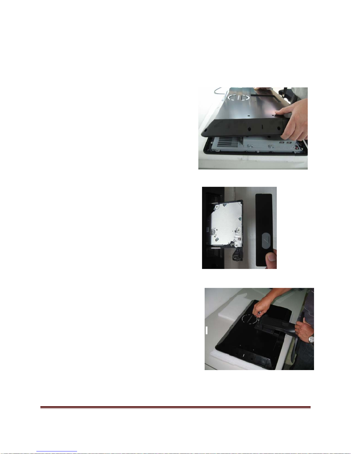
C22 Series Disassembly
ORIENTATION: Presumes the top of the LCD PC is away from you and the bottom or I/O
controller board is nearest you. Do not put any pressure on the LCD PC to avoid adding
pressure to the System or place any equipment/device on top of it during
assembly/disassembly.
1. Place the LCD PC face down on a padded surface.
2. Remove the four screws from the base plate that attaches the stand to the LCD.
Supporting the base while removing the last screw.
3. Open the ODD button rubber and use paper clip to eject the ODD tray. Remove the
ODD bezel and put it at the side, push the ODD tray back to the unit.
4. Remove the thirteen back bezel screws.
5. Carefully remove the back bezel and set aside.
6. Then remove the metal EMI shield by first removing the I/O cover by removing the
three screws on the bottom and another three screws on the surface. Lift the plate
out and up and set aside.
7. Remove the remaining twelve screws around the metal shield covering the
motherboard.
C22 Series System Assembly
Page 22

Figu
r
P
e
p
s
e 12: Op
n system
ithout GP
U
Fig
ure 13: O
en syste
with GPU
C22 Se
ies
age 23
Sy
tem Assembly

Install
r
a
q
o
P
a
r
s
h
a
u
o
y
t
e
v
l
s
a
m
a
g
P
m
s
o
e
a
s
s
l
C
e
n
s
s
d
d
o
k
e
m
h
o
ng the
PU
NOTE:
instructi
purchas
access
If you pur
ns to rem
ed as ‘bar
ries box w
hased you
ve the he
bones’ re
th the unit.
LCD PC
t sink in o
uire the in
1. T
2. R
s a turn-k
der to be
tallation o
e socket
th
e pins fro
place unti
in
ise the pl
pi
ns and op
p
lling out a
C
U socket.
y system,
ble to rea
the heat
as a plasti
damage.
actually i
stic cap t
n the cov
d up on t
ou must fi
h the CPU
ink which i
c cap on it
This shou
stalling a
reveal th
r by pushi
e lever be
rst follow t
. Systems
shipped i
to protect
d remain
PU.
socket
g down,
ide the
e
n the
NOTE:
damag
Any violati
to your m
on of the c
therboard
3. In
Note
direc
emb
with
4. C
in
rrect inst
.
N
te: Do no
dama
stall the C
fo
r correct
b
the edge
: The CP
ion. Mak
dded into
ertical mo
ose the co
tallation.
llation pro
touch the
e.
U after c
ating. Be
of the CP
can only
sure the
the socket
tion and re
ver and th
Replace th
edures m
socket pin
nfirming th
ure to hol
base.
be installe
CPU pins
. If not, ta
install.
lever to c
e heat sin
y cause p
to avoid
e direction
the CPU
in the c
are compl
ke out the
mplete
.
rmanent
rrect
etely
CPU
C22 Se
ies
age 24
Sy
tem Asse
bly

P
t
e
e
a
e
c
a
m
m
i
M
y
a
t
o
e
m
n
h
a
e
P
r
a
e
a
s
e
c
h
s
o
a
e
o
e
c
a
o
m
a
i
a
s
Install
ng the
PU Heat
Sink
1. Pu
fou
hol
2. Alt
bal
Note:
th
3. Se
ne
4. Re
ther
ded
Note:
has m
install
5.. Pu
tw
th
6. Re
the
7. Co
Mot
on the he
screws fi
s on the
rnate pre
nce.
Do not fix
ir position
ure the tw
r the top
ove the th
al pad fr
cated Gra
ake sure
lar to isola
tion.
on the G
screws fi
motherbo
ove the p
same surf
nect the p
erboard l
t sink and
the corre
otherboa
sure while
ny screws
.
o screws
dge of the
ree protec
m GPU H
hics).
that the b
tor from M
U Heatsin
the corre
rd.
otective fil
ce as the
ower cabl
beled CP
make sur
ponding s
d.
securing t
until the fo
t the oppo
bezel.
ive films c
atsink (m
ttom of th
inboard c
k and mak
ponding s
m from the
Fan of the
to CPU F
FAN 1 c
that the
rew
e Screws
ur screws
ite end
vering the
inboard w
GPU Hea
mponents
sure that
rew holes
thermal p
GPU Heat
n on the
nnector.
with
re in
th
tsink
after
the
on
d on
ink.
C22 Se
ies
age 25
Sy
tem Asse
bly

Install
M
P
D
D
e
h
a
r
s
e
s
y
o
e
n
m
M
t
m
ng the
emory
odule D
3 SO-
IMM
1. The m
and wil
2. Insert t
slot at
golden
deeply
mory mod
only fit in
e memo
45° angl
finger on t
inserted in
le has onl
he slot on
module in
. Then pu
e memor
the DIMM
y one notc
way.
to the DIM
h it in unti
module is
slot.
h
l the
C22 Se
ies
3. Press t
metal c
autom
4. Repeat
modul
age 26
e memor
lip at each
tically clos
the steps
to meet y
module d
side of th
e.
o install a
ur needs.
Sy
wn and th
DIMM slo
other me
tem Asse
e
will
ory
bly

Install
n
n
u
e
o
o
a
o
S
H
i
D
s
w
r
o
A
m
v
.
ng the
ard Disk PDrive
1. I
a
fo
S
C
2.
stall the h
d line up t
screw h
cure the f
nnect the
Connect t
Connect t
rd disk wit
e hard dis
le accord
ur screws
SATA cabl
e SATA c
e Power c
h the HDD
k bracket
ingly.
on the Ha
e to the m
ble,
able
bracket
ith
d Disk Dri
therboard
e.
C22 Se
ies
3. C
ca
.
nnect the
ble to the
age 27
ther end
ard Disk
f the SAT
rive as sh
r Cable
Sy
/Power
own.
tem Asse
bly

P
D
h
o
e
e
r
s
t
a
m
D
m
L
v
Install
ng the
ptical Di
k Drive
1.
PC
fram
2.
the f
3. S
Remove
isassembl
e.
Put the
ur screw
ecure the f
back bez
y. Remov
DD on th
oles acco
ur screw
l as indica
the Optic
ODD fra
dingly.
on the O
ed in the
l Disk Dri
e and line
D frame.
CD
e
up
C22 Se
ies
age 28
Sy
tem Asse
bly

P
P
s
r
4. Con
a
s
u
c
M
s
f
f
o
m
h
e
D
ower Cab
ect the S
e.
TA cable.
Connect t
e
5. Co
ODD.
6. Inst
crew hole
7. Sec
f
ame and
nnect the
ll the ODD
over the
re the two
omplete t
ther end o
frame and
etal Supp
screws to
e installati
the cable t
line up th
ort.
ix the OD
n.
o the
two
C22 Se
ies
age 29
Sy
tem Asse
bly

Install
p
2
n
o
s
n
w
a
d
C
a
r
m
ng the
ini-PCIe PCard (O
tional)
1. The mi
notch a
Insert t
Then, p
fingers
deeply i
slots.
. Press d
and se
i-PCIe car
d will onl
e mini-PC
ush it in u
n the mini
nserted in
own the m
ure with th
s have o
fit in one
Ie card at
til the gold
-PCIe car
the mini-P
ni-PCIe c
e small sc
ly one
ay.
45° angle
en
are
Ie
rd
ews.
.
C22 Se
ies
age 30
Sy
tem Asse
bly
D
a
w
a
o
P
t
O
s
Install
1. Sec
2. Sec
3. In
4. Se
ng the
ring the m
re the pla
tall the O
cure the st
over
tal cover
tic cover
D bezel b
and with f
nd I/O pla
ith thirteen
ck to the
ur screws.
e with eig
screws.
DD.
teen scre
s.
C22 Se
ies
age 31
Sy
tem Assembly

P
Sy
s
tem Vie
C22 Se
ies
age 32
System Assembly
 Loading...