

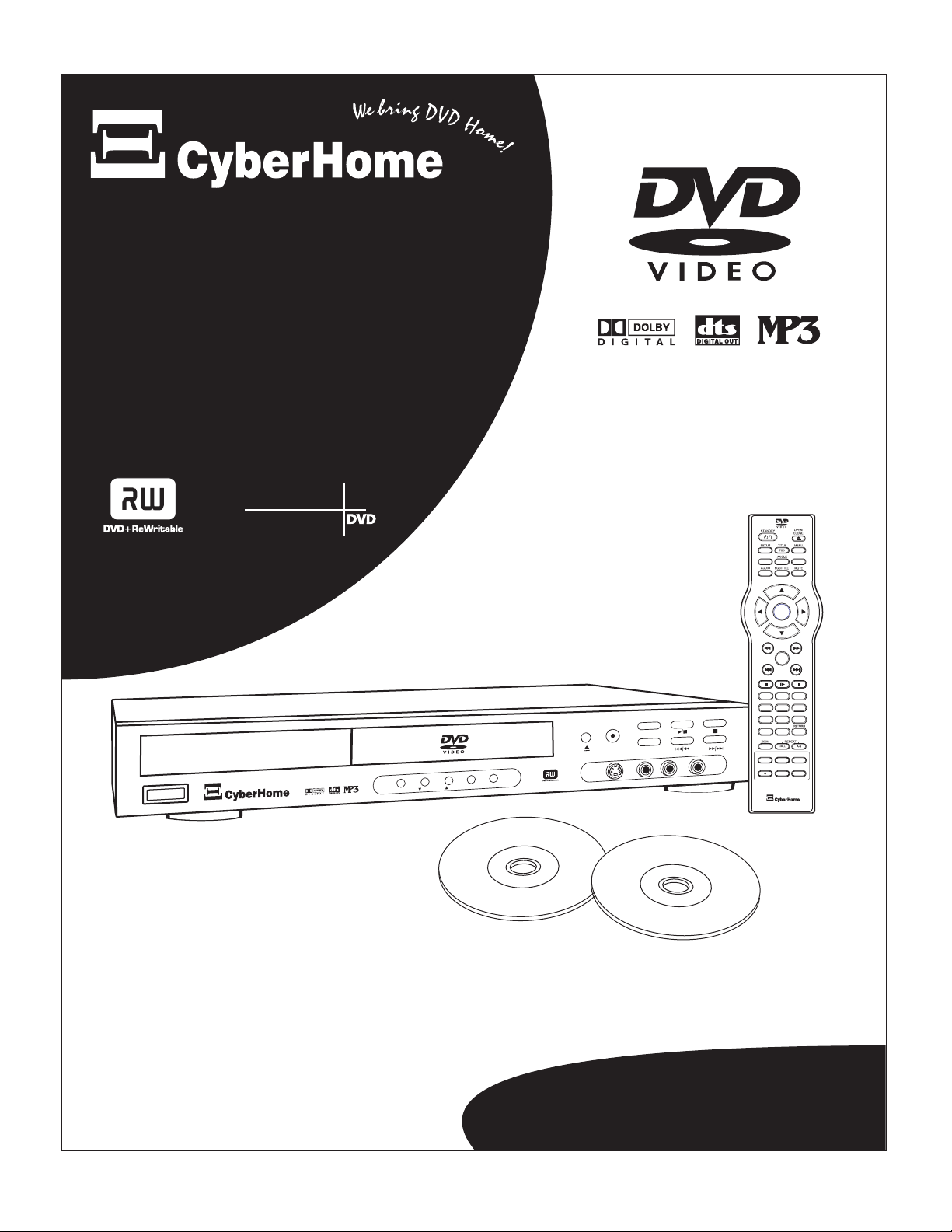
CyberHome Entertainment CH-DVR 1500 User Manual
Digital
Video
Recorder
PROGRESSIVE
SCAN
YS
B
D
N
A
/
T
ON
TM
TM
TM
BOOKMARK
DISPLAY
CH+
ENTER
CH-
PLAY
1 2 3
1 2 3
4 5 6
4 5 6
7 8 9
7 8 9
C-SKIP
+10 0 C
DVD/TV LIVE
REC
SOURCE
REC MODE
0 C
TIMER
EDIT
MT
N
R
U
T
E
R
R
E
T
EN
P
U
N
O
DW
P
U
T
E
S
R
E
C
U
O R
S
EO
VID
R
-
I O
D
A
-
L U
EO
D
VI
-
S
I
L
V
T VE
/
VD
D
D
R
O
EC
Operation Guide
CH-DVR 1500
SAFETY INSTRUCTIONS
CAUTION
RISK OF ELECTRIC SHOCK
RISK OF ELECTRIC SHOCK
DO NOT OPEN
DO NOT OPEN
CAUTION: TO REDUCE THE RISK OF ELECTRIC SHOCK, DO NOT
REMOVE THE COVER (OR BACK). NO USER-SERVICEABLE PARTS
INSIDE. REFER TO QUALIFIED SERVICE PERSONNEL FOR SERVICING.
Explanation of warning symbols
The lightning flash with arrowhead symbol, within an
equilateral triangle, is intended to alert the user to the presence
of not isolated dangerous voltage within the inside of the
product that may be sufficient magnitude to constitute a risk of
electric shock to persons.
The exclamation point within an equilateral triangle is
intended to alert the user to the presence of important
operating and servicing instructions in the literature
accompanying the appliance.
Read the following instructions carefully
WARNING: TO REDUCE THE RISK OF FIRE, ELECTRIC SHOCK OR
ANNOYING INTERFERENCE, DO NOT EXPOSE THIS APPLIANCE TO RAIN OR
MOISTURE AND ONLY USE THE RECOMMENDED ACCESSORIES.
Read these instructions - When using this unit, basic precautions
outlined in this section should always be followed.
Keep these instructions - Retain this user manual for future
reference.
Heed all warnings - Follow all warning labels on the product, and
the safety instructions in this manual.
Follow all instructions - Adhere to the instructions outlined in this
manual and on the unit.
Clean only with a dry cloth - Unplug the unit before cleaning. Do
not use any liquid or detergents for cleaning.
Do not block any ventilation opening. Install in accordance with
the manufacture's instructions.
Do not install near any heat sources such as radiators, heat
registers, stoves, or other apparatus (including amplifiers) that
produce heat.
Do not defect the safety purpose of the polarized plug. A polarized
plug has two blades with one wider than the other. The wide blade
is provided for your safety. If the provided plug does not fit into
your outlet, consult an electrician for replacement of the obsolete
outlet.
Protect the power cord from being walked on or pinched
particularly at plugs, convenience receptacles, and the point where
they exit from the apparatus.
Only use attachments / accessories specified by the manufacturer.
The apparatus shall not be exposed to dripping or splashing and no
objects filled with liquids, such as vases, shall be placed on the
apparatus.
Use only with the cart, stand, tripod, bracket, or
table specified by the manufacturer, or sold with
the apparatus. When a cart is used, use caution
when moving the cart / apparatus combination to
avoid injury from tip-over.
Unplug this apparatus during lightning storms or
when unused for long periods of time.
Refer all servicing to qualified service personnel. Servicing is
required when the apparatus has been damaged in any way, such
as when the power-supply cord or plug is damaged, liquid has
been spilled, objects have fallen into the apparatus, the apparatus
has been exposed to rain or moisture, or when the unit does not
operate normally, or has been dropped.
Power cord protection - To avoid any malfunctions of the unit
and to protect against electric shock, fire or personal injury,
please observe the following:
a) Hold the plug firmly when connecting or disconnecting the
AC power cord to this unit.
b) Do not connect or disconnect the AC power cord with wet
hands.
c) Keep the AC power cord away from heating appliances.
d) Never put any heavy object on the AC power cord.
e) Do not attempt to repair or reconstruct the AC power cord in
any way.
Remove dust, dirt, etc. on the plug at regular intervals.
If the unit has been dropped or otherwise damaged, turn off the
power and disconnect the AC power cord.
If smoke, odors or noises are emitted from the unit, turn off the
power and disconnect the AC power cord.
Placement - Avoid placing the unit in areas of direct sunlight,
heating radiators, closed automobiles, high temperature (over 35°
C (95° F)), high humidity (over 90%), excessive dust, vibration,
impact or where the surface is tilted, as the internal parts may be
seriously damaged.
Non-use periods - When the unit is not used, turn the power off.
When the unit is unused for a long period of time, the unit should
be unplugged from the household AC outlet.
No fingers or other objects inside - Touching internal parts of this
unit is dangerous and may cause serious damage to the unit. Do
not attempt to disassemble the unit.
Do not put any foreign object on the disc tray.
Keep away from water and magnets.
Keep the unit away from flower vases, tubs, sinks, etc. If liquids
are spilled into the unit, serious damage could occur.
Keep magnetic objects, such as speakers, distant from the player.
Stacking - Place the unit in a horizontal position and do not place
anything heavy on it.
Do not place the unit on amplifiers or other equipment which
may become hot.
Condensation - Moisture may form on the lens in the following
cases: a) immediately after a heater has been turned on b) in a
steamy or very humid room c) the unit is moved from a cold
environment to a warm one.
If moisture forms inside this unit, it may not operate properly. In
this case, turn off the power and wait about one hour for the
moisture to evaporate.
Noise interference while a broadcast is being received -
depending on the reception condition of the TV, interference may
appear on the TV screen while you are watching a TV broadcast,
if the unit is switched on. This is not a malfunction of the unit or
the TV. To watch a TV broadcast, turn off this unit.
Caution - Use of controls or adjustments or performance of
procedures other than those specified herein may result in
hazardous radiation exposure.
SAVE THESE INSTRUCTIONS
2

CONTENTS
INTRODUCTION
Features.................................4
Optical disc compatibility . . . . . . . . . . . . . . . . . . . 5
Caring for optical discs.....................5
GETTING STARTED
Checking the package contents . . . . . . . . . . . . . . . 6
Installing batteries in the remote control . . . . . . . . 6
Using the remote control....................6
FUNCTIONAL OVERVIEW
Remote control functions. . . . . . . . . . . . . . . . . . . . 7
Front panel functions.......................8
Front VFD display.........................9
Back panel connections....................10
CONNECTIONS
Video connection to TV . . . . . . . . . . . . . . . . . 11-12
Audio output connections . . . . . . . . . . . . . . . . . . 13
Antenna connections......................13
A/V input connections.....................14
OPERATION OVERVIEW
Powering on the unit......................15
Initial Setup.............................15
PLAYBACK
Selecting the DVD function . . . . . . . . . . . . . . . . 16
Using disc menus.........................16
Basic disc playback.......................17
Advanced disc playback . . . . . . . . . . . . . . . . . . . 18
Using the ZOOM feature...................19
Multi-angle function ......................19
Using subtitles...........................20
Changing the audio track. . . . . . . . . . . . . . . . . . . 20
Displaying playback information . . . . . . . . . . . . 20
Viewing JPG files ........................21
Playing MP3 ............................22
Timer Recording.........................28
EDITING YOUR RECORDINGS
The EDIT menu..........................30
Erasing a Title...........................30
Play Full Title ...........................30
Make Compatible ........................30
Finalize ................................30
Edit Title ...............................31
Inserting Chapter Markers . . . . . . . . . . . . . . . . . . 31
Deleting Chapter Markers..................32
Hiding Chapters..........................32
The HIDE Button.........................33
Show Chapters...........................33
New Picture.............................34
Erasing a DVD+RW disc...................34
THE DVD RECORDER SETUP MENU
Using the Setup Menu.....................35
Language Settings........................35
Video Setup.............................36
Audio Setup.............................36
System Setup............................37
Disc Media Options.......................38
Record Mode Options.....................38
Timer Record............................38
TROUBLESHOOTING
Playback................................39
Recording...............................39
SPECIFICATIONS
.......................................40
INDEX
.......................................41
RECORDING
Intro to recording.........................23
Setting recording options...................24
Setting the Time and Date..................24
TV Tuner Setup..........................25
The Title Navigator screen . . . . . . . . . . . . . . . . . 26
Types of Recordings ......................26
Making a Live Recording . . . . . . . . . . . . . . . . . . 26
3
INTRODUCTION
CH-DVR 1500 Personal DVD+R/RW Recorder and Progressive Scan Player
TM
TM
BOOKMARK
JPG
PROGRESSIVE
Y
B
D
TAN
/
N
O S
SCAN
P
U
T
E
S
E
V
L
V I
T
/
D
V
D
D
OR
C
E
TM
N
R
U
T
E
R
R
E
T
N
E
P
U
N
OW
D
R
E
C
R
OU
S
O
E
D
I
V
O
I
D
A R
L- U
O
E
D
I
V
-
S
DISPLAY
1 2 3
1 2 3
4 5 6
4 5 6
7 8 9
7 8 9
C-SKIP
+10 0 C
DVD/TV LIVE
REC
REC MODE
CH+
ENTER
CH-
PLAY
0 C
SOURCE
TIMER
EDIT
TM
two-way
compatible
TWINWAY
The CH-DVR 1500 is a DVD Recorder/Player with Progressive Scan Video Output. DVD+R/RW Recording gives you
the ability to create your own DVD discs from your home movies, favorite TV programs and more. Because of the
outstanding compatibility of DVD+R/RW discs, the discs you create will be suitable for playback in most DVD
players. You can record from the unit's built-in TV Tuner or an external video source like a video camera. And when
you're ready to watch your recordings or commercial DVDs, you can enjoy them in the highest quality with the unit's
Progressive Scan Video Out and Digital Audio Out.
DVD+R/RW Recorder
Live, Timer and Scheduled Recording Functions
Multiple Recording Modes, HQ, SP, LP, EP, SLP
Up to 6 Hours Recording on one DVD+R/RW Disc
On-Screen Disc Title Navigator gives you quick, easy
access to your Recordings
Built-In TV Tuner, Front and Rear A/V Inputs
Editing features with Auto, Add/Del, Hide Chapters
Your recordings are playable on most DVD Players
Progressive Scan DVD Player
Progressive Scan Video with 3:2 pulldown
Plays DVD, VCD/SVCD, CD-ROM, MP3, JPG and
other disc types
Component Video, S-Video and Composite Video
Outputs
96 kHz / 24 bit D/A converter
Stereo Audio out, Optical and Coaxial digital outputs.
Advanced playback functions: Slow playback, repeat
playback, parental control, MP3 player, JPG player,
screen saver, Zoom In/Out, track selection, on-screen
display and more
4
INTRODUCTION
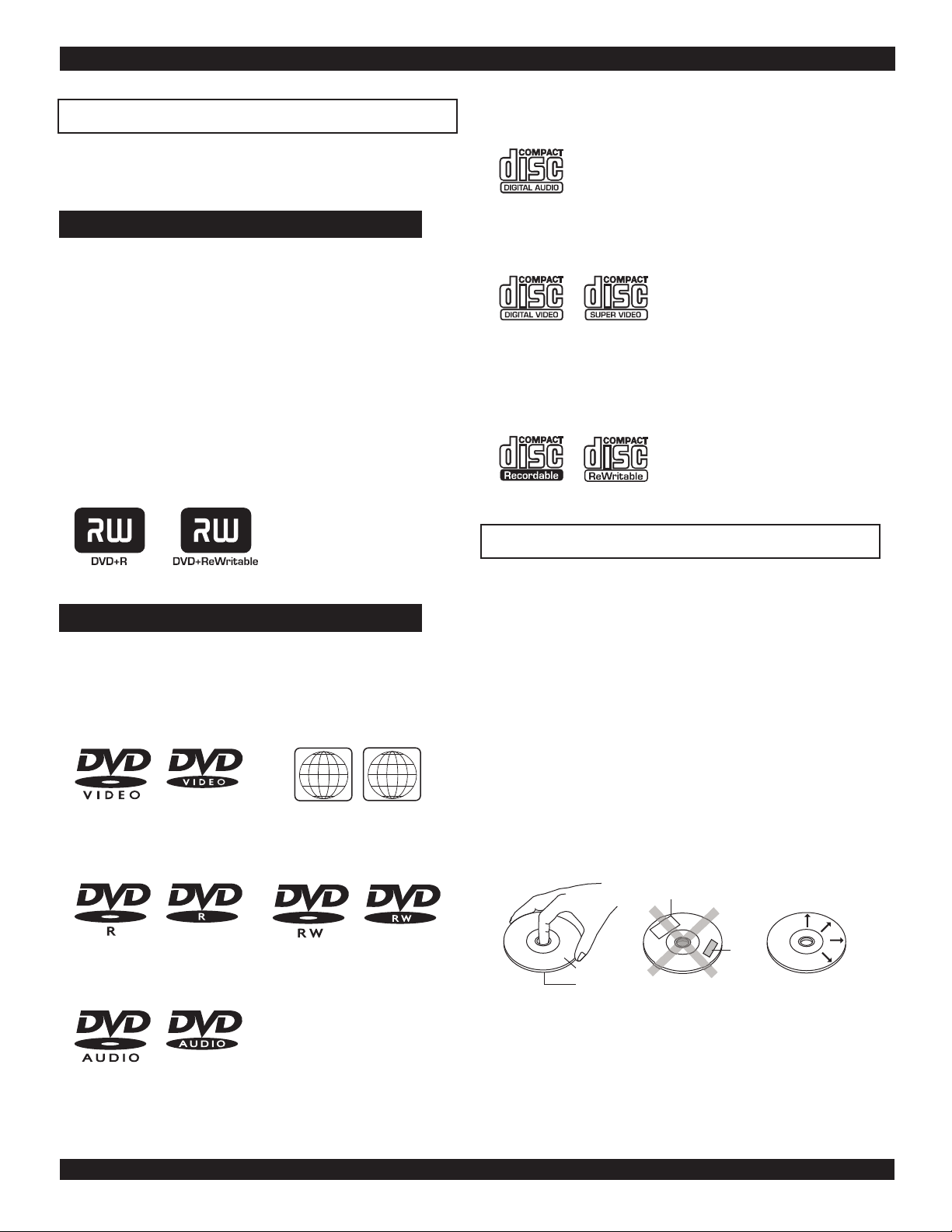
Optical disc compatibility
This unit is compatible with a wide range of available optical
discs for recording and playback.
Discs suitable for Recording and Playback
You must us DVD+R or DVD+RW discs to record on this unit.
DVD+R: These discs can only be written to once. Existing
recordings can be hidden but not deleted. So, any disc space
already used by a recording cannot be regained. DVD+R discs
are required to be "Finalized" before they will be compatible
with standard DVD Players. Once a disc is finalized, no further
recordings can be made.
DVD+RW: DVD+RW discs can be written to and erased
multiple times. Existing recordings can be deleted and disc space
regained. These discs do not require a finalization procedure. As
soon as a recording is made, the disc will be compatible with
standard DVD Players.
CD-Audio: An on-screen navigator is provided to select and
play tracks when using CD-Audio discs.
Video CD - VCD/SVCD: On VCD/SVCD discs, advanced
features such as PBC (Playback Control) are available.
CD-R/RW: This unit features an on-screen navigator for easy
access to playable files stored on CD-R/RW discs, such as JPG
images and MP3 music.
Caring for Optical Discs
Discs suitable for Playback Only
DVD Video: This unit plays DVDs recorded for a particular
region. The region mark on the back of the player must
correspond to that on any DVD discs you wish to play. Units
sold in North America are coded for Region 1, and are
compatible with discs marked accordingly.
TM TM
11
DVD-R/RW: These discs can be played back when recorded in
standard DVD Video format.
TM TM
DVD-Audio: This unit will playback only the 5.1CH sound
track on DVD-Audio discs.
ALLALL
TM TM
Hold a disc by the rim or with an index finger in the central
hole. Never touch the signal surface.
Finger prints or stains on the surface of the disc may cause
signal loss.
Use a soft cloth and wipe in a radiating manner from the
center of the disc to the outer rims when cleaning the disc
surface.
Never add labels or adhesive tapes on the discs and be
careful not to scratch or damage the disc surface.
To prevent discs from becoming bent or deformed, they
should be vertically kept in the disc storage case. To prevent
damage, avoid leaving discs in your car, where they may be
subject to direct sunlight and high temperature.
Do not use any disc accessory to improve the audio quality,
disc protective solutions or lens cleaner. These products may
damage the disc surface.
Labels
Tapes
Labeling Side
Surface
TM TM
5
INTRODUCTION
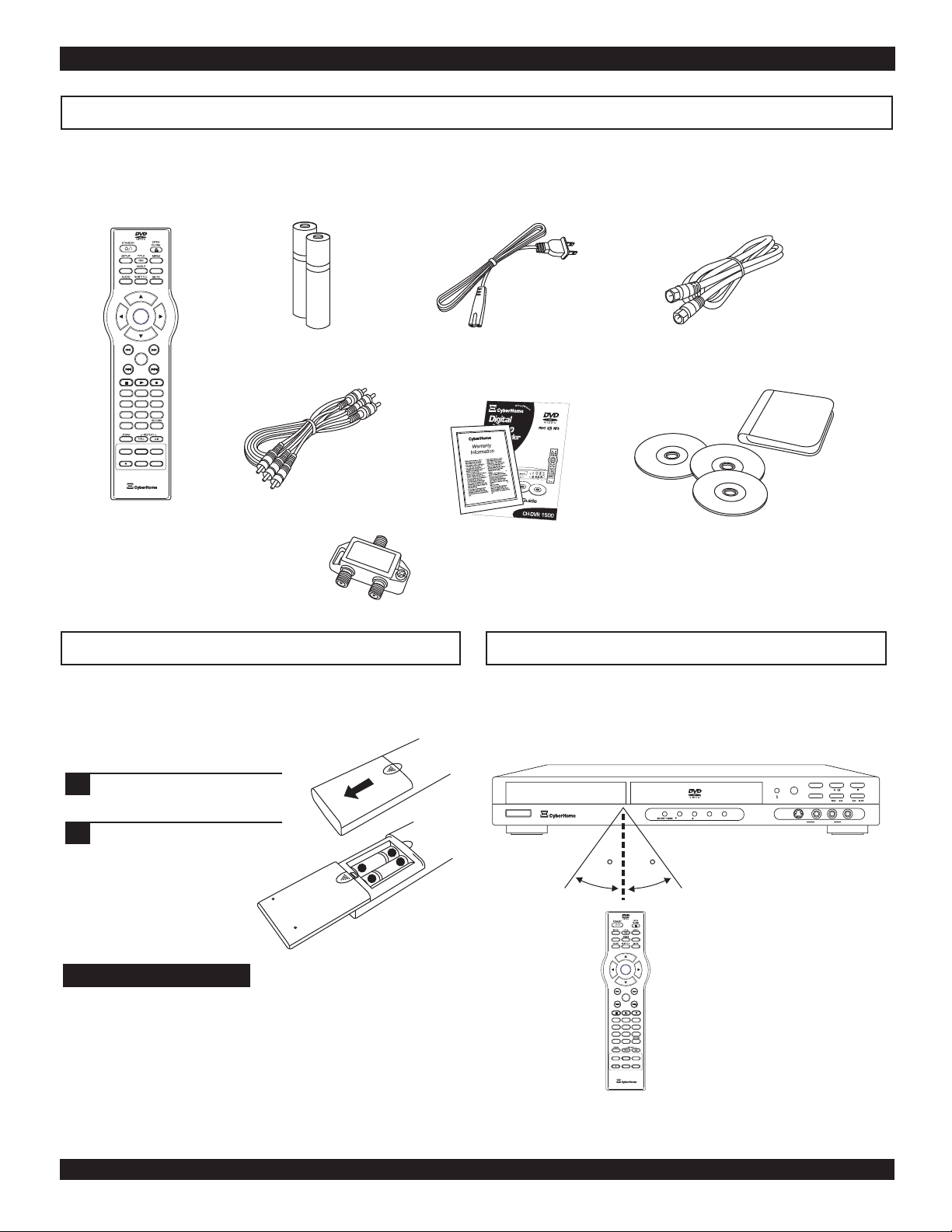
Make sure the package contents are complete
In addition to the DVD/Receiver, your package should contain the following accessories. Check the contents of the package carefully,
as some items may be located under the packing foam.
Remote control
TM
TM
BOOKMARK
DISPLAY
CH+
ENTER
CH-
PLAY
1 2 3
1 2 3
4 5 6
4 5 6
7 8 9
7 8 9
C-SKIP
+10 0 C
0 C
SOURCE
TIMER
DVD/TV LIVE
REC
REC MODE
EDIT
*Optional Splitter for
units without Antenna
Passthrough Connector
Batteries (2) AAA
A/V cable (Composite
Video, Stereo Audio)
(See page 13)
Power cord
This operation manual
and warranty card
11
RF Cable for TV
Blank DVD+RW Discs (3)
& Disc Holder
Installing batteries in the remote control
This unit comes complete with batteries for the remote control.
When installing batteries, be sure to take note of the polarity
markings on the inside of the battery compartment and match
them up with those on the batteries.
Slide off the back cover.
1
Install the batteries in the
2
correct orientation as
shown to the right and
marked on the battery
compartment.
Notes on batteries
If the remote control functions better when it is closer to
the unit, the batteries may be running low.
In case of any leakage of batteries, dispose of the batteries
right away and avoid touching the chemical discharge.
Make sure to clean the remote control’s battery
compartment before installing new batteries.
Do not mix batteries of different types, or use old batteries
with new ones.
+
-
-
+
Operating the remote control
When using the remote control, be sure to stay within a 30
degree angle of the sensor on the receiver. Keep in mind that
any obstructions between the remote control and the receiver
will effect performance.
-
-
CH DVR 1500 DVD PLAYER RECORDER
ON / STANDBY
30 30
TM
TM
BOOKMARK
DISPLAY
CH+
ENTER
CH-
PLAY
1 2 3
1 2 3
4 5 6
4 5 6
7 8 9
7 8 9
C-SKIP
+10 0 C
0 C
SOURCE
TIMER
DVD/TV LIVE
REC
REC MODE
EDIT
DOWN
RETURNENTER
UP
DVD / TV LIVE
/
RECORD
SOURCE
/
L
RAUDIO
S-VIDEO IN 2 VIDEO IN 2
/
6
Remote Control
FUNCTIONAL OVERVIEW
15
17
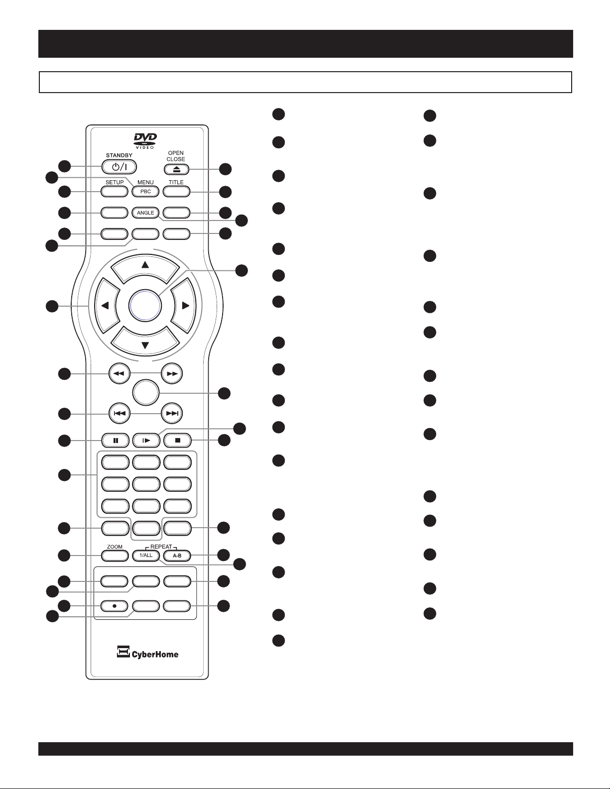
STANDBY - Turns the unit on and
1
sends the unit to Standby mode.
TM
MENU / PBC - Accesses Menus
2
on DVD Discs. With VCD discs,
turns the PBC function On/Off.
1
2
3
BOOKMARK
DISPLAY
4
5
6
DIGEST
HIDE
AUDIO SUBTITLE MUTE
CH+
18
19
20
22
21
SETUP - Accesses the on-screen
3
Setup Menu for settings
adjustment.
DISPLAY - Brings up the on-
4
screen display showing
information for the playback
session.
5
AUDIO - Selects an audio track on
DVD or VCD discs.
21
23
SUBTITLE - Selects available
6
subtitles on DVD discs.
ARROW KEYS (CH+/-) - Use to
7
ENTER
7
navigate disc menus, on-screen
setup menu, etc. In TV tuner mode,
use UP/DOWN to select a channel.
FF/FR - Scan in fast forward or
8
reverse on DVD and other discs.
10
CH-
8
PLAY
9
24
25
26
1 2 3
11
4 5 6
NEXT/PREVIOUS - Advanced to
9
the next track or plays previous
track on DVD and other disc.
10
PAUSE - Use to Temporarily stop
play.
NUMBER KEYS - Use to enter
11
numeric values while setting
options.
C-SKIP - Skips ahead in 30
12
second intervals during playback.
This function is intended to assist
in skipping over commercials
during playback of TV recordings.
12
13
14
16
7 8 9
C-SKIP
REC
SOURCE
REC MODE
DVD/TV LIVE
0 C
TIMER
EDIT
25
27
28
29
30
31
31
ZOOM - Press to magnify the
13
screen with DVD and JPG discs.
DVD/TV LIVE - Switches between
14
Live Recording mode and DVD
Player mode.
SOURCE - Selects the input video
15
source for recording. Choices
include built-in TV Tuner and AV
Inputs.
REC - Press to begin a live
16
recording.
REC MODE - Selects the
17
recording quality mode - HQ, SP,
OPEN / CLOSE - Opens and
18
closes the disc tray.
TITLE - Accesses the title screen
19
on DVD+R/RW discs, displaying a
graphical representation of the
recordings and providing easy
navigation.
BOOKMARK / HIDE - In DVD
20
Playback mode, use to store
specific locations on a disc for
quick navigation. When editing
recordings sets start and end points
for hiding specific sections.
DIGEST / ANGLE - Displays
21
thumbnail images for previewing
files on JPG discs. Selects between
multiple angles with DVD Discs
that support this feature.
MUTE - Temporarily cancels
22
audio playback.
ENTER - Selects options in
23
menus. Plays a disc, chapter or
track with some discs. For other
discs, press PLAY.
PLAY - Plays a disc, chapter or
24
track.
SLOW - Slow motion playback
25
mode in ½,1/4 or 1/8 speed. Press
PLAY to resume normal playback.
STOP - Press once to stop
26
playback and hold the last position
in memory. Playback can be
resumed where it was left off by
pressing PLAY. Press twice to
clear the last playback position.
CLEAR - When entering input,
27
use to delete characters.
A-B REPEAT - Sets the
28
beginning and end points of a
section to repeat.
REPEAT 1/ALL - Selects a
29
repeat option - Chapter, Title or
Disc.
TIMER - Accesses the timer menu
30
for scheduled recording setup.
EDIT - Accesses the edit menu for
31
DVD+R/RW editing options.
LP, SLP, EP.
7
Front Panel
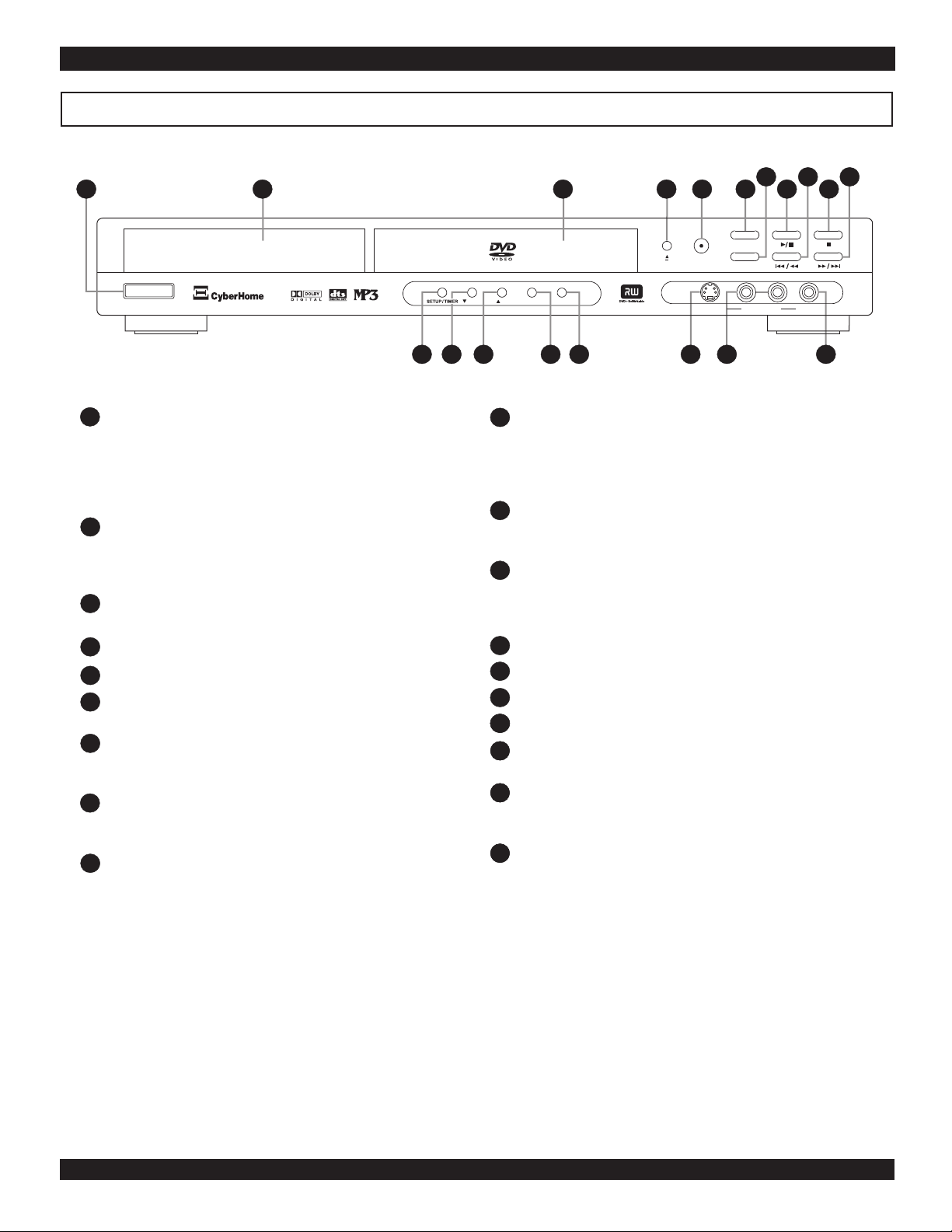
1
FUNCTIONAL OVERVIEW
2 3
9
7
8
6
54
10
11
-
CH DVR 1500 DVD PLAYER RECORDER
ON / STANDBY
ON / STANDBY - Turns the unit on and sends the STOP - Press once to stop playback of a disc and save
1
-
PROGRESSIVE SCAN VIDEO
12
13 14
DOWN
10
TM
UP
RETURNENTER
15 16
17 18 19
DVD / TV LIVE
RECORD
SOURCE
L
S-VIDEO IN 2 VIDEO IN 2
RAUDIO
unit to standby mode. The main power switch on the the location of the stop point. The disc can be played
back of the unit must be turned on before using the back from the stop point by pressing PLAY. To erase the
standby button. In standby mode, the unit will use a stop point and reset the play location to the beginning of
minute amount of power to enable power-on by the the disc, press STOP a second time.
remote control.
VFD DISPLAY - The front Vacuum Flourescent next chapter or track. Press and HOLD to scan in reverse
2
NEXT/FAST FORWARD - Press to advance to the
11
Display shows information about the unit’s operation, mode at 2X, 4X, 8X, 16X, 30X or 60X speed.
such as current chapter and elapsed time during
playback and disc tray status.
DISC TRAY - Loads DVD+R/RW, DVD, CD-ROM, options and settings for the Recorder. Use the Timer for
3
SETUP/TIMER - Accesses the On-Screen Setup Menu
12
and Timer Schedule screen. Use SETUP to change
VCD/SVCD, MP3, JPG and other optical discs. scheduling recordings that will begin automatically.
OPEN/CLOSE - Press to open or close the disc tray. DOWN - Navigates downward in menus, etc.
4
RECORD - Begins a Live Recording. UP - Navigates upwards in menus, etc.
5
DVD/TV LIVE - Switches from DVD playback mode ENTER - Confirms a choice in menus or settings.
6
to Live Recording Input mode.
SOURCE - Selects between available Input Sources
7
when the Recorder is in Live Record mode - TV Tuner,
VIDEO IN 1 / 2, S-VIDEO IN 1 / 2.
PLAY/PAUSE - Begins playback of a disc, chapter or
8
track. Press again during playback to pause, and again
to resume playback.
PREV/FAST REVERSE - Press to return to the
9
previous chapter or track. Press and HOLD to scan in
reverse mode at 2X (twice normal speed). Press and
hold again repeatedly to scan at 4X, 8X, 16X, 30X or
13
14
15
13
16
RETURN - Returns to the previous menu.
S-VIDEO IN 2 - Front S-Video Input for recording. To
11
17
select, use the SOURCE key and select S-VIDEO IN 2.
14
18
LEFT/RIGHT AUDIO IN 2 - Front Stereo Audio
Inputs for recording. These inputs are shared with the
VIDEO IN 2 and S-VIDEO IN 2 inputs.
15
19
COMPOSITE VIDEO IN 2 - Front Composite Video
Input for recording. To select, use the SOURCE key and
select VIDEO IN 2.
60X speed.
8
Front VFD Display
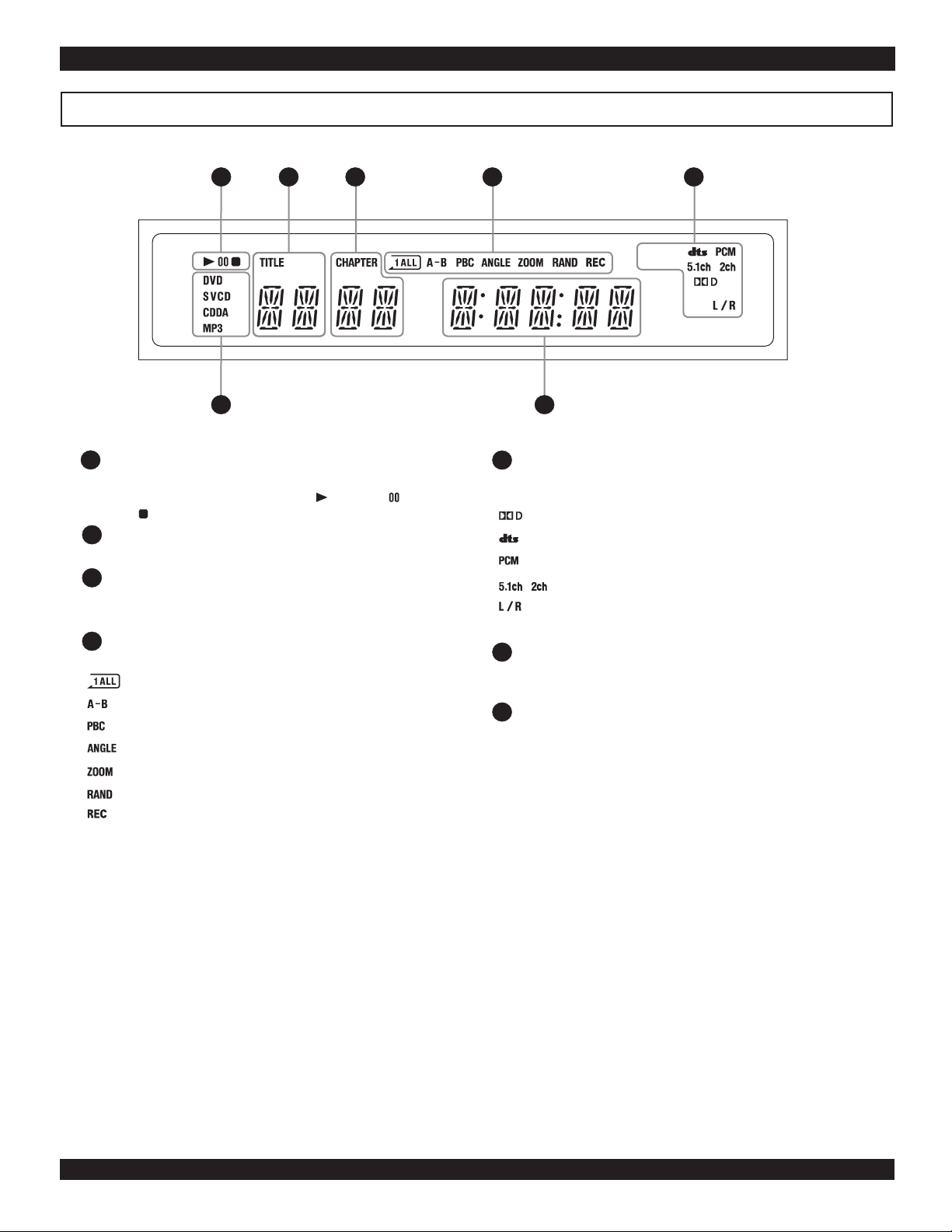
FUNCTIONAL OVERVIEW
1 2 3 4 5
6 7
1
PLAYBACK INDICATORS PROCESSOR INDICATORS
5
These indicators show the playback status of a DVD, CD or These indicators display the status of the surround sound
other optical disc - Currently Playing: , Paused: , processors and type of sound track currently active.
Stopped:
2
TITLE INDICATOR
Displays the number of the current Title on a DVD disc.
3
CHAPTER / PRESET INDICATOR
Displays the number of the current Chapter or Track on
DVDs, Music CDs and other discs.
4
FUNCTION INDICATORS
Indicate the status of advanced disc playback functions:
Repeat Chapter/Title/Track function is active.
Repeat A-B Function is active.
PBC (Playback Control) Function is enabled.
Multi-Angle Mode is active.
The Zoom function is being used.
Tracks are being played in RANDOM order.
6
Displays the type of optical disc inserted - DVD, SVCD,
VCD, CDDA (Music CD), or MP3.
7
When playing a DVD or other optical disc, displays the
elapsed time of the playback session or track. Also displays
disc tray status, system messages and more. When the unit is
in Standby Mode, displays the system clock.
The Dolby Digital processor is active.
The DTS Digital processor is active.
The PCM Digital Stereo processor is active.
Indicates 5.1 Channel or Stereo audio source.
The L/R option is active.
DISC TYPE INDICATORS
MULTI-FUNCTION DISPLAY
Recording indicator.
9
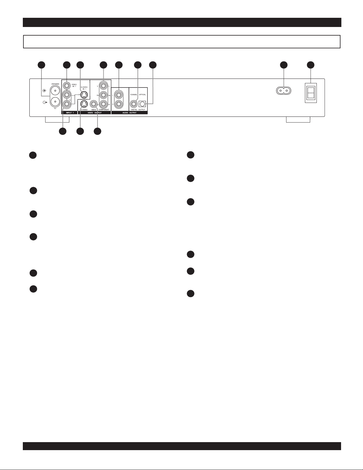
Back Panel
FUNCTIONAL OVERVIEW
1
1
ANTENNA IN / OUT - For Antenna or Cable TV OPTICAL DIGITAL AUDIO OUTPUT - Use to
3
2
121110
5
4
7
6
7
AC IN
~100-230V
8 9
connection. Passthrough connection to TV does not connect to a receiver or other device with 5.1 channel
transfer the output signal from the DVD Recorder. decoders. This output is the coded digital signal.
*Some units do not have a Passthrough connector. In this
case, use the included splitter (See page 13).
2
VIDEO INPUT 1 - Composite Video input for other end to the wall socket.
recording. To select this input, use the SOURCE button
and choose VIDEO IN 1.
3
S-VIDEO INPUT 1 - S-VIDEO input for recording. To
select this input, use the SOURCE button and choose SVIDEO IN 1.
4
COMPONENT/PROGRESSIVE SCAN VIDEO
OUTPUT - Use this output with TVs supporting
Component Video or Progressive Scan input for best
video quality. Select this output in the DVD Recorder’s
SETUP MENU.
STEREO AUDIO OUTPUT - Connect to TVs or other
5
audio equipment supporting Stereo Audio in.
6
COAXIAL DIGITAL AUDIO OUTPUT - Use a
special coaxial digital audio connector to send the raw
coded digital signal to devices supporting digital
8
POWER CORD SOCKET - Plug the matching end
of the power cord into the unit before connecting the
9
MAIN POWER SWITCH - The main power
switch must be set to ON for the unit to function. Make
sure all cable connections are complete before
switching the main power switch to ON. When the
main power switch is turned ON, the unit will enter
Standby Mode, where it may be turned on with the
remote control or the front power switch.
10
STEREO AUDIO INPUTS - Use with S-VIDEO IN
1 or VIDEO IN 1 for recording.
S-VIDEO OUTPUT - Connect to TVs with S-VIDEO
11
in for better picture quality than standard composite
video.
12
COMPOSITE VIDEO OUTPUT - Standard Video
Output supported by most TVs.
decoding.
ON
I
O
OFF
10
CONNECTIONS
Connecting the video output to your TV
In order to use the DVD Recorder, you’ll need to make a video connection to your TV. The capabilities of your TV and the cables
you have on hand will determine the connections you can use. There are 3 possible connection types:
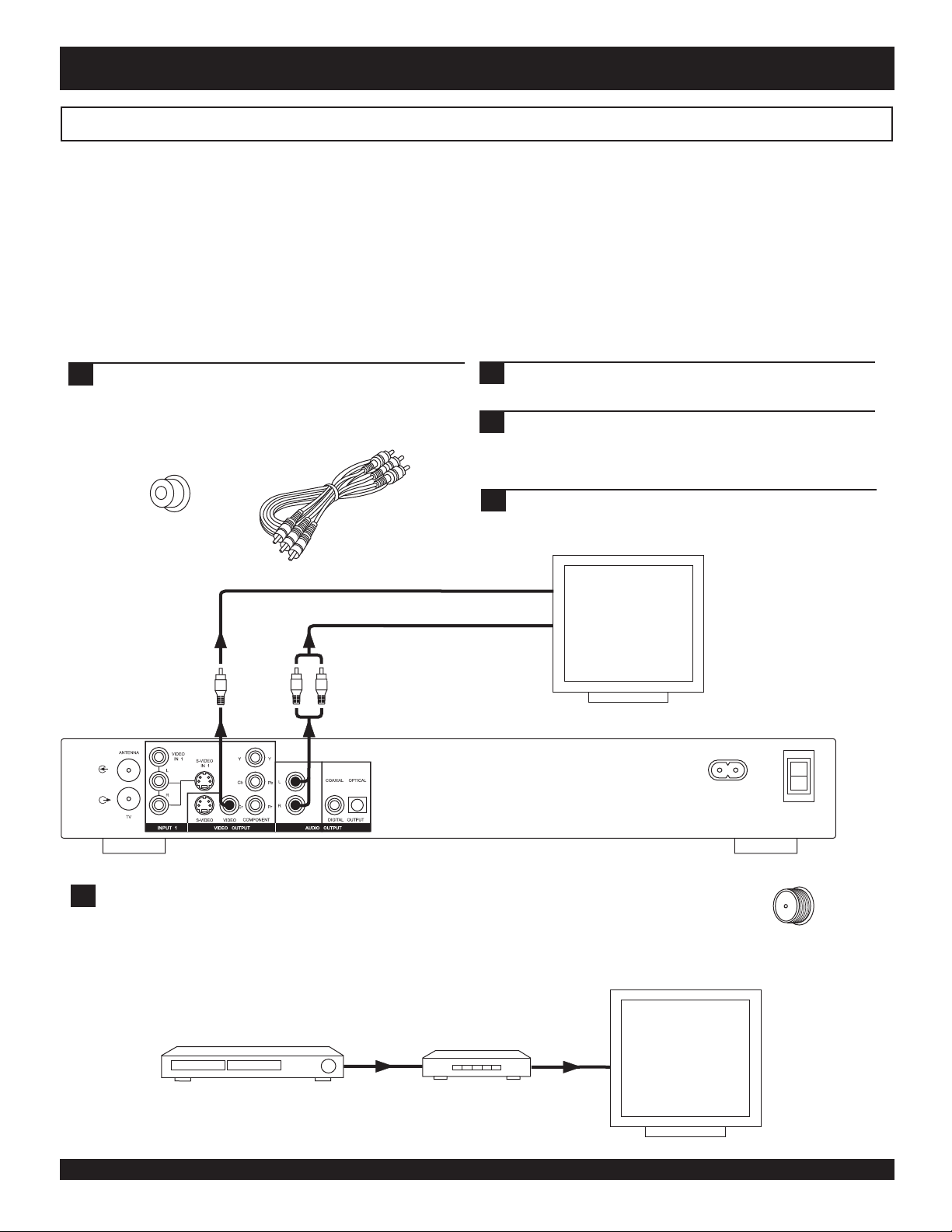
Composite Video - The most widely used connection. This unit includes an A/V cable for Composite Video.
S-Video - A higher quality connection that requires a special S-Video cable and an S-Video capable TV.
Component Video - The highest quality video connection. Supported on high-end TVs and requires a special cable.
Composite Video (Typical connection)
This unit ships with a composite video (A/V) cable for connection to TVs with a standard video input as shown below. This is the
most widely used type of connection. On most TVs, this connector is colored yellow, and is normally accompanied by stereo audio
inputs, colored red and white for stereo channels right and left, respectively.
First, use the supplied A/V cable to connect to the
1
composite video input on your TV. This is normally a
yellow-colored connector that matches the Video output
on the back of this unit. If you wish to hear sound
through the TV, connect the red and white stereo audio
connections as well.
Composite Video
Input Jack
V
Composite Video /
Stereo Audio Cable
R
L
Turn on the TV and DVD Recorder and select the DVD
2
Playback mode with the remote control.
On your TV, select the video input. This is normally done
3
by selecting “Video 1” or “Video Input” with the remote
control. On some TVs, this is done by selecting a
particular channel.
You should now see the DVD Recorder’s splash screen
4
on the TV.
VIDEO INPUT
STEREO AUDIO IN
TV with
Composite
Video Input
(Typical
Connection)
AC IN
~100-230V
ON
I
O
OFF
!
Important note for older TV models
If your TV does not have a composite video-in jack like that pictured above, you cannot connect this
unit directly. If this is so, check to make sure your TV has at least a coaxial connector (used for
antenna/cable TV/VCR/etc.) such as that pictured to the right. In this case, you can use a RF
Modulator to convert this unit’s video out to the coaxial connection on your TV. RF Modulators are
available at major electronics retailers.
Older TV with
coaxial
antenna/cable
connector
DVD Recorder
Composite Video Out
RF Modulator
11
Antenna/cable TV
coaxial connector
on older TVs
CONNECTIONS
S-Video
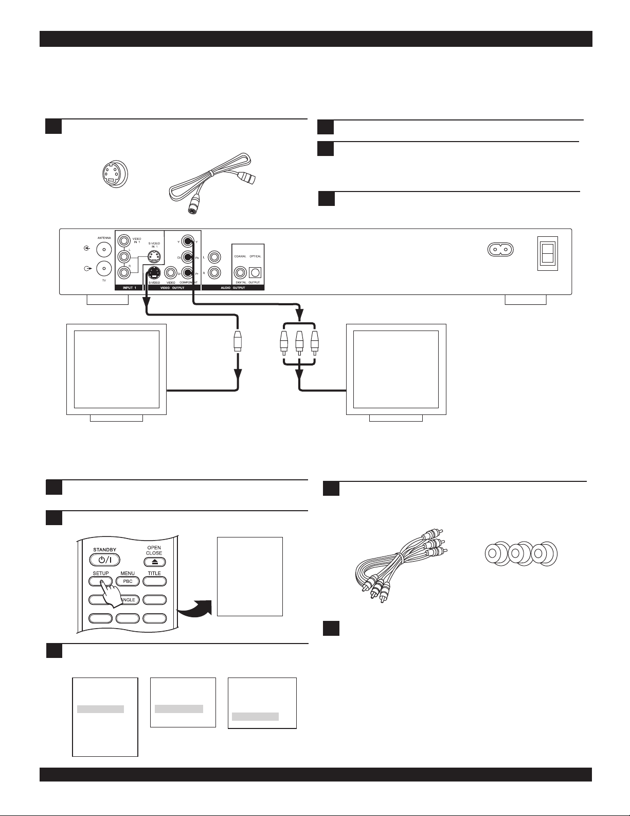
This is a higher quality connection than standard composite video, and requires a special S-Video cable not included. The S-Video
connector is distinguishable by its 4 pins, as shown below. If your TV has an S-Video input, it’s recommended that you use this type
of connection for better picture quality.
First, obtain a special S-Video cable. Connect the S-
1
Video output from the unit to the corresponding input
on your TV.
S-Video
S-Video Cable
Input Jack
TV with
S
S-Video Input
VIDEO
INPUT
Y Pb Pr
2
3
4
VIDEO
INPUT
Turn on the unit and select the DVD mode.
On your TV, select the S-Video input. This is normally
done by selecting “Video 2” or “AV2” with the remote
control. On some TVs, this is done by selecting a
particular channel.
You should now see the DVD player’s splash screen on
the TV.
ON
AC IN
~100-230V
I
O
OFF
TV with
Component
Video Input /
Progressive Scan
capability.
Component Video
The highest quality video connection, component video requires separate cables for the Y, Pb, Pr signals. To use the progressive scan
option on this unit, you’ll need to use the component video output. Using the component video output requires these steps:
First, use the supplied A/V cable to connect to the
1
composite video input on your TV. Select this input.
Enter the player’s Setup Menu by pressing SETUP on the
2
remote control.
SETUP
Language
Video Setup
Audio Setup
System Setup
DISPLAY
AUDIO SUBTITLE MUTE
Change the VIDEO OUTPUT setting under VIDEO SETUP
3
to COMPONENT. If you are using a Progressive Scan TV,
HIDE
BOOKMARK
DIGEST
Disc Media
Record Mode
Timer Record
change the OUTPUT FORMAT to PROGRESSIVE.
SETUP
Language
Video Setup
Audio Setup
System Setup
Disc Media
Record Mode
Timer Record
VIDEO SETUP
Aspect Ratio
Video Output
Output Format
VIDEO OUTPUT
Composite
S-Video
Component
Press SETUP to exit the SETUP MENU and connect the
4
Component Video cables. Select the correct video input
on your TV.
Y Pb Pr
Component
Video Cable
!
Resetting the video output
Component Video
Input Jacks
If you inadvertently switch the OUTPUT FORMAT setting to
PROGRESSIVE while using a standard TV not capable of PSCAN, you will loose video. If this happens, reset the recorder
to its default video settings by following these steps:
1) Power the unit Off, then On again with the main power
switch on the back.
2) Eject the disc and close the disc tray.
3) Press and hold the STOP button on the front panel for 3 full
seconds.
12
CONNECTIONS
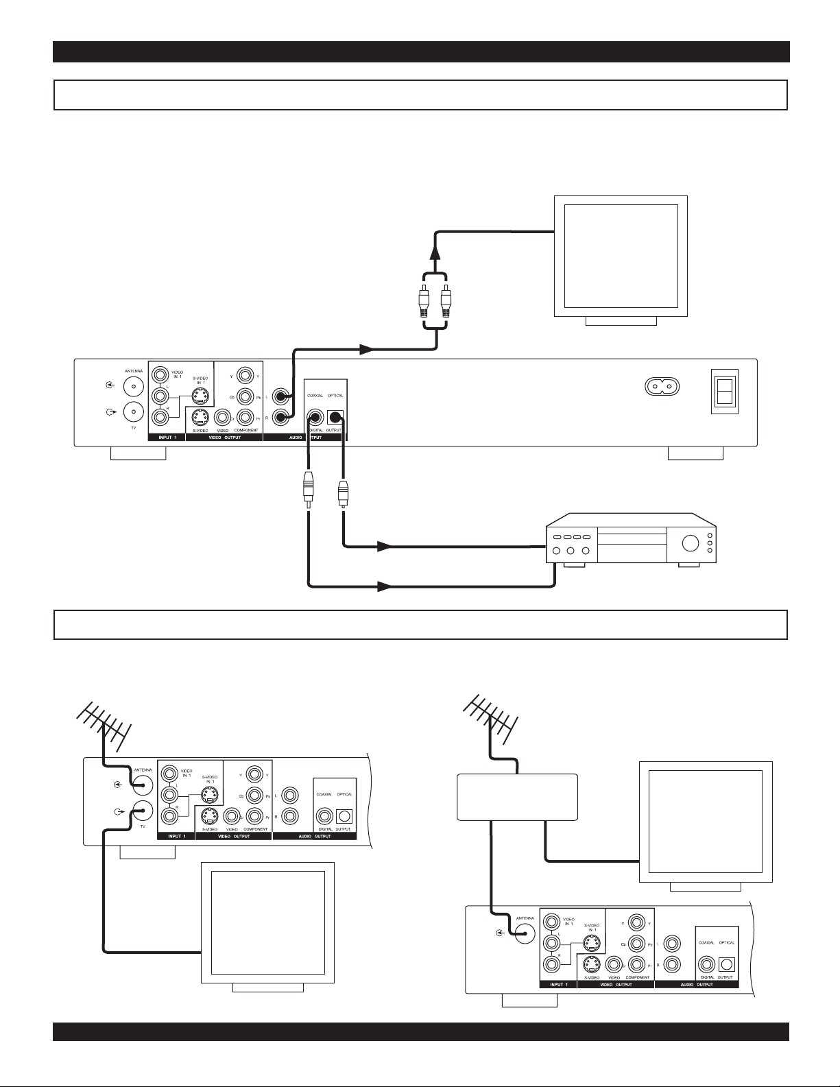
Audio Output Connections
This unit features a variety of audio line outputs for connection to a receiver or other audio equipment.
Use the included A/V cable to connect the stereo audio outputs for connection to a TV or stereo receiver.
Optical and Coaxial digital audio outputs send an encoded digital bitstream, suitable for receivers with Dolby or DTS decoding
capability. These outputs require special cables not included.
STEREO AUDIO IN
TV or receiver
with stereo
audio in
R
L
AC IN
~100-230V
ON
I
O
OFF
Receiver with Digital
Audio Input
OPTICAL DIGITAL AUDIO IN
COAXIAL DIGITAL AUDIO IN
Antenna & TV Connections
This unit is available with and without an antenna passthrough connection. For units with only an Antenna input connector, as shown
below to the right, use the included Splitter to connect a single RF input signal to the recorder and a TV.
With Passthrough Connector Without Passthrough Connector
ANTENNA OR CABLE TV CONNECTION
OR
ANTENNA OR CABLE TV CONNECTION
IN
Splitter
OUT OUT
TV with
coaxial
antenna or
cable TV
connection
TV with
coaxial
antenna or
cable TV
connection
13
 Loading...