


CyberGuard SG
User Manual
CyberGuard
7984 South Welby Park Drive #101
Salt Lake City, Utah 84084
Email: support@cyberguard.com.au
Web: www.cyberguard.com
Revision 3.1.2
December 20th, 2005

Contents
1. Introduction...............................................................................................1
CyberGuard SG Gateway Appliances (SG3xx, SG5xx Series).............................1
CyberGuard SG Rack Mount Appliances (SG7xx Series).....................................4
CyberGuard SG PCI Appliances (SG6xx Series)..................................................7
Document Conventions .......................................................................................10
2. Getting Started........................................................................................11
CyberGuard SG Gateway Appliance Quick Setup ..............................................12
CyberGuard SG Rack Mount Appliance Quick Setup .........................................12
CyberGuard SG PCI Appliance Quick Setup.......................................................23
The CyberGuard SG Management Console........................................................41
3. Network Setup.........................................................................................43
Configuring Connections .....................................................................................43
Multifunction vs. Fixed-function Ports ..................................................................44
Direct Connection ................................................................................................46
ADSL ...................................................................................................................49
Cable Modem ......................................................................................................54
Dialout and ISDN.................................................................................................55
Dialin....................................................................................................................56
Failover, Load Balancing and High Availability....................................................61
Internet Failover...................................................................................................63
Internet Load Balancing.......................................................................................67
High Availability ...................................................................................................69
DMZ Network.......................................................................................................72
Guest Network.....................................................................................................74
Wireless...............................................................................................................76
Bridging................................................................................................................87
VLANs..................................................................................................................91
Port Based VLANs...............................................................................................93
GRE Tunnels .......................................................................................................97
Routes ...............................................................................................................101
System...............................................................................................................109
DNS...................................................................................................................110

DHCP Server.....................................................................................................111
Web Cache........................................................................................................116
QoS Traffic Shaping ..........................................................................................123
IPv6....................................................................................................................125
4. Firewall ..................................................................................................126
Incoming Access................................................................................................126
Web Server........................................................................................................128
Customizing the Firewall....................................................................................130
Definitions..........................................................................................................131
Packet Filtering..................................................................................................134
Network Address Translation (NAT)..................................................................137
Connection Tracking..........................................................................................149
Intrusion Detection.............................................................................................150
Basic Intrusion Detection and Blocking (IDB)....................................................151
Advanced Intrusion Detection and Prevention (Snort and IPS).........................154
Access Control and Content Filtering................................................................157
Antivirus.............................................................................................................169
5. Virtual Private Networking...................................................................180
PPTP and L2TP.................................................................................................181
PPTP VPN Server .............................................................................................181
L2TP VPN Server ..............................................................................................189
PPTP and L2TP VPN Client ..............................................................................196
IPSec.................................................................................................................198
Set Up the Branch Office...................................................................................199
Configuring the Headquarters............................................................................211
Tunnel List .........................................................................................................214
NAT Traversal Support......................................................................................217
Dynamic DNS Support.......................................................................................217
Certificate Management.....................................................................................217
IPSec Troubleshooting ......................................................................................222
Port Tunnels ......................................................................................................225
6. USB........................................................................................................229
USB Mass Storage Devices ..............................................................................229
USB Printers......................................................................................................236

Printer Troubleshooting .....................................................................................242
USB Network Devices and Modems..................................................................243
7. System...................................................................................................244
Date and Time ...................................................................................................244
Backup/Restore Configuration...........................................................................245
Users .................................................................................................................248
Management......................................................................................................252
Diagnostics ........................................................................................................255
Advanced...........................................................................................................256
Reboot and Reset..............................................................................................259
Flash upgrade....................................................................................................260
Configuration Files.............................................................................................262
Support..............................................................................................................263
Appendix A – Terminology...........................................................................265
Appendix B – System Log............................................................................272
Access Logging .................................................................................................272
Creating Custom Log Rules...............................................................................274
Rate Limiting......................................................................................................277
Administrative Access Logging..........................................................................278
Boot Log Messages...........................................................................................278
Appendix C – Firmware Upgrade Practices and Precautions...................279
Appendix D – Recovering From a Failed Upgrade .....................................281

1. Introduction
This manual describes the features and capabilities of your CyberGuard SG appliance,
and provides you with instructions on how to best take advantage of them.
This includes setting up network connections (in the chapter entitled Network
Connections), tailoring the firewall to your network (Firewall), and establishing a virtual
private network (Virtual Private Networking). It also guides you through setting up the
CyberGuard SG appliance on your existing or new network using the web management
console (Getting Started).
This chapter provides a high level overview to familiarize you with your CyberGuard SG
appliance’s features and capabilities.
CyberGuard SG Gateway Appliances (SG3xx, SG5xx Series)
Note
The CyberGuard SG gateway appliance range includes models SG300, SG530, SG550,
SG560, SG565, SG570, SG575 and SG580.
The CyberGuard SG gateway appliance range provides Internet
security and privacy of communications for small and medium
enterprises, and branch offices. It simply and securely connects
your office to the Internet, and with its robust stateful firewall,
shields your computers from external threats.
With the CyberGuard SG appliance’s masquerading firewall, hosts on your LAN (local
area network) can see and access resources on the Internet, but all outsiders see is the
CyberGuard SG appliance’s external address.
You may tailor your CyberGuard SG appliance to disallow access from your LAN to
specific Internet sites or categories of content, give priority to specific types of network
traffic, and allow controlled access to your LAN from the outside world. You may also
choose to enable intrusion detection and prevention services on your CyberGuard SG
appliance, to further bolster the security of your local network.
Introduction
1
The SG565, SG560, SG570, SG575 and SG580 may also connect to a DMZ
(demilitarized zone) network. A DMZ is a separate local network typically used to host
servers accessible to the outside world. It is separated both physically and by the
firewall, in order to shield your LAN from external traffic.
The CyberGuard SG appliance allows you to establish a virtual private network (VPN). A
VPN enables remote workers or branch offices to connect securely to your LAN over the
public Internet. The CyberGuard SG appliance can also connect to external VPNs as a
client. The SG550, SG560, SG565, SG570, SG575 and SG580 utilize onboard
cryptographic acceleration to ensure excellent VPN throughput.
The CyberGuard SG appliance may be configured with multiple Internet connections.
These auxiliary connections may be kept on stand-by should the primary connection
become unavailable, or maintained concurrently with the primary connection for
spreading network load.
The SG565, SG570, SG575 and SG580 incorporate a powerful web proxy cache to
improve web page response time and reduce link loads. It is designed to integrate
seamlessly with upstream proxy caches provided by ISPs.
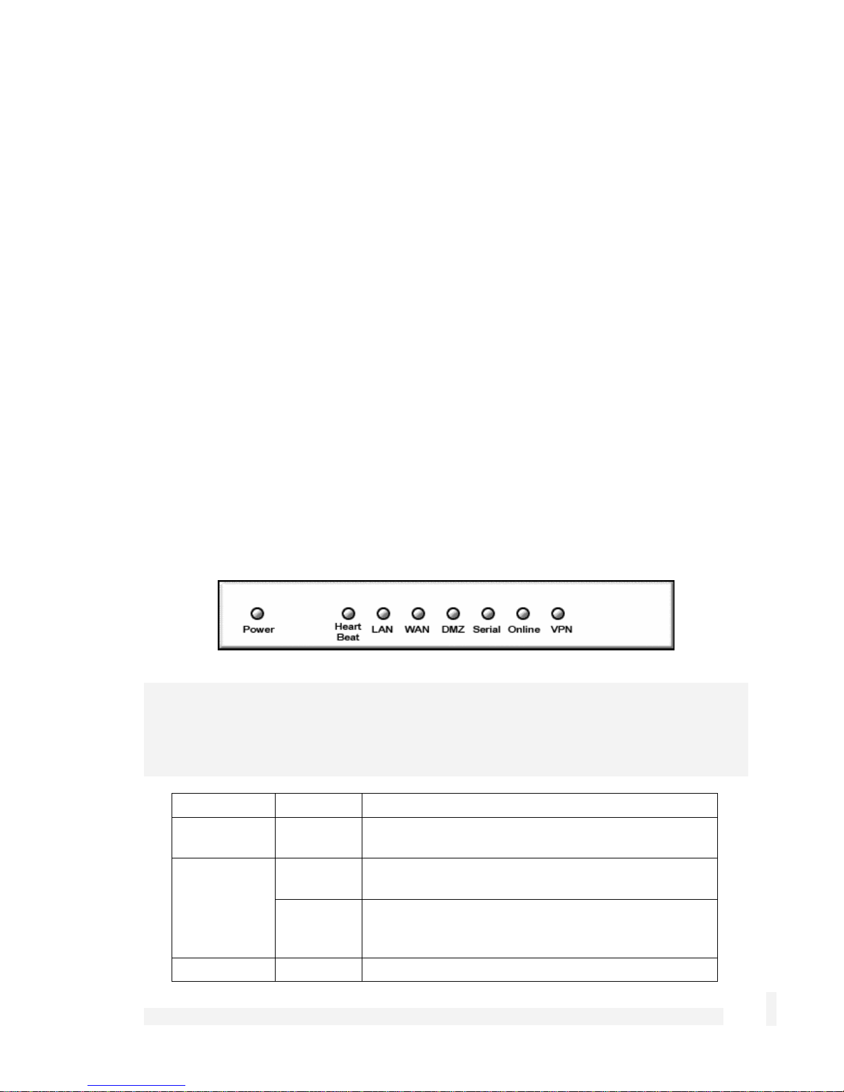
Front panel LEDs
The front and rear panels contain LEDs indicating status. An example of the front panel
LEDs are illustrated in the following figure and detailed in the following table.
Note
Not all the LEDs described below are present on all CyberGuard SG appliance models.
Labels vary from model to model.
Label Activity Description
Power
On Power is supplied to the CyberGuard SG
appliance
Heart Beat
Flashing The CyberGuard SG appliance is operating
correctly
On If this LED is on and not flashing, an operating
error has occurredError! Reference source not
found.
LAN Activity
Introduction
Flashing Network traffic on the LAN network interface
2

WAN Activity
Flashing Network traffic on the Internet network interface
WLAN
DMZ Activity
Serial
Activity
HA
Flashing Network traffic on the Wireless network interface
Flashing Network traffic on the DMZ network interface
Flashing For either of the CyberGuard SG appliance COM
ports, these LEDs indicate receive and transmit
data
On The CyberGuard SG appliance has switched to a
backup device
Online
VPN
Online
On An Internet connection has been established
On Virtual private networking is enabled
On An Internet connection has been established
Note
If Heart Beat does not begin flashing shortly after power is supplied, refer to Appendix D,
Recovering From a Failed Upgrade.
Rear panel
The rear panel contains Ethernet and serial ports, the Reset/Erase button and power
inlet. If network status LEDs are present, the lower or left LED indicates the link
condition, where a cable is connected correctly to another device and the upper or right
LED indicates network activity.
Specifications
Internet link
• 10/100baseT Ethernet
• Serial (for dial-up/ISDN)
• Front panel serial status LEDs (for TX/RX)
• Online status LEDs (for Internet/VPN)
• Rear panel Ethernet link and activity status LEDs
Introduction
3

Local network link
• 10/100BaseT LAN port (SG530, SG550)
• 10/100BaseT 4 port LAN switch (SG300)
• 10/100BaseT DMZ port (SG570, SG575)
• 10/100BaseT 4 port VLAN-capable switch (SG560, SG565, SG580)
• Rear panel Ethernet link and activity status LEDs
Enviromental
• External power adaptor (voltage/current depends on individual model)
• Front panel operating status LEDs: Power, Heart Beat
• Operating temperature between 0° C and 40° C
• Storage temperature between -20° C and 70° C
• Humidity between 0 to 95% (non-condensing)
CyberGuard SG Rack Mount Appliances (SG7xx Series)
Note
The CyberGuard SG rack mount appliance range includes models SG710 and SG710+.
The CyberGuard SG7xx series is the flagship of CyberGuard’s
SG family. It features multi-megabit throughput, rackoptimized form factor, two fast Ethernet ports and two 4 port
fast Ethernet switches as standard, and the option for two
additional gigabit ports (SG710+).
In addition to providing all of the features described in CyberGuard SG Gateway
Appliances earlier in this chapter, it equips central sites to securely connect hundreds of
mobile employees and branch offices.
Introduction
4
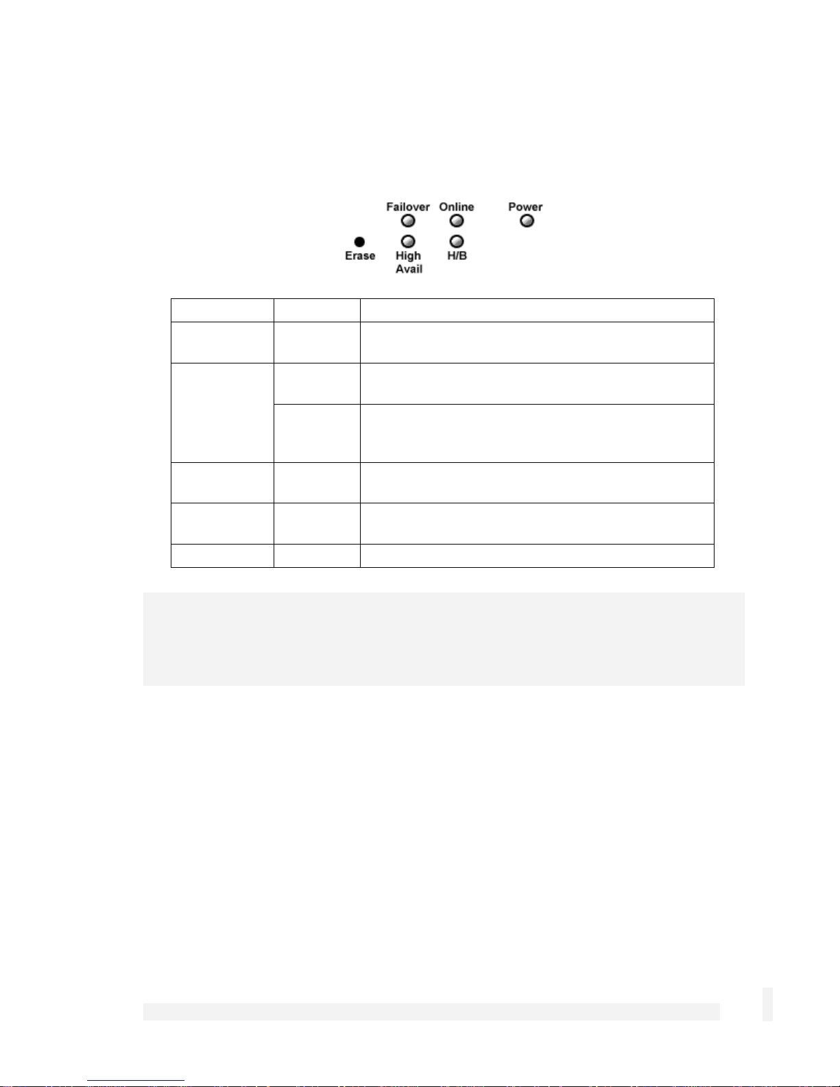
Front panel LEDs
The front panel contains LEDs indicating status. An example of the front panel LEDs are
illustrated in the following figure and detailed in the following table.
Label Activity Description
Note
If H/B does not begin flashing 20 – 30 seconds after power is supplied, refer to Appendix
E, Recovering From a Failed Upgrade.
Front panel
Power
H/B (Heart
Beat)
Failover
High Avail
Online
On Power is supplied to the CyberGuard SG
appliance
Flashing The CyberGuard SG appliance is operating
correctly
On If this LED is on and not flashing, an operating
error has occurredError! Reference source not
found.
On The CyberGuard SG appliance has switched to
the backup Internet connection
On The CyberGuard SG appliance has switched to a
backup device
On An Internet connection has been established
The front panel contains two 10/100 Ethernet four port switches (A and B), two 10/100
Ethernet ports (C and D) and analog/ISDN modem (Serial) as well as operating status
LEDs and the configuration reset button (Erase).
On the front panel Ethernet ports, the right hand LED indicates the link condition, where a
cable is connected correctly to another device. The left hand LED indicates network
activity.
Introduction
5

Rear panel
The rear panel contains a power switch and a power inlet for an IEC power cable.
Additionally, the SG710+ has two gigabit Ethernet ports (E and F).
Specifications
Internet link
• Two 10/100baseT Ethernet ports (C, D)
• Two GbE ports (E, F – SG710+ only)
• Serial port
• Online status LEDs (Online, Failover)
• Ethernet link and activity status LEDs
LAN/DMZ link
• Two 10/100BaseT 4 port LAN switches
• Ethernet link and activity status LEDs
Enviromental
• Front panel operating status LEDs: Power, H/B
• Operating temperature between 0° C and 40° C
• Storage temperature between -20° C and 70° C
• Humidity between 0 to 95% (non-condensing)
Introduction
6

CyberGuard SG PCI Appliances (SG6xx Series)
Note
The CyberGuard SG PCI appliance range includes models SG630 and SG635.
The CyberGuard SG PCI appliance is a hardware based
firewall and VPN server embedded in a 10/100 Ethernet PCI
network interface card (NIC). It is installed into the host PC
like a regular NIC, providing a transparent firewall to shield
the host PC from malicious Internet traffic, and VPN services
to allow secure remote access to the host PC.
Unlike other CyberGuard SG gateway and rack mount appliances, a single CyberGuard
SG PCI appliance is not intended as a means for your entire office LAN to be connected
to, and shielded from, the Internet. Installing a CyberGuard SG PCI appliance in each
network connected PC gives it its own independently manageable, enterprise-grade VPN
server and firewall, running in isolation from the host operating system.
This approach offers an increased measure of protection against internal threats as well
as conventional Internet security concerns. You can update, configure and monitor the
firewall and VPN connectivity of a workstation or server from any web browser. In the
event of a breach, you have complete control over access to the host PC independent of
its operating system, even if the host PC has been subverted and is denying normal
administrator access.
All network filtering and CPU intensive cryptographic processing is handled entirely by
the CyberGuard SG appliance. This has the advantage over the traditional approach of
using a host-based personal software firewall and VPN service by not taxing the host
PC's resources.
Bridged mode
By default, the CyberGuard SG PCI appliance operates in bridged mode. This is
distinctly different from the masquerading behavior of CyberGuard SG gateway and rack
mount appliances.
In bridged mode, the CyberGuard SG PCI appliance uses two IP addresses. Note that
these addresses are both in the same subnet as the LAN, as no masquerading is being
performed (refer to the Masquerading section of the chapter entitled Firewall for further
details).
Introduction
7
One IP address is used to manage the CyberGuard SG appliance via the web
management console.
The other is the host PC's IP address, which is configurable through the host operating
system, identically to a regular NIC. This is the IP address that other PCs on the LAN
see. It should be dynamically (DHCP) or statically configured to use the same gateway,
DNS, etc. settings as a regular PC on the LAN.
Note
It is possible to configure the CyberGuard SG PCI appliance to run in masquerading
mode. This is discussed in the chapter entitled Firewall.
Secure by default
By default, all CyberGuard SG appliances run a fully secured stateful firewall. This
means from the PC that it is plugged into, most network resources are freely accessible.
However, any services that the PC provides, such as file shares or web services (e.g. IIS)
are not be accessible by other hosts on your LAN without further configuration of the
CyberGuard SG appliance. This is accomplished using packet filter rules, for details refer
to the Packet Filtering section of the chapter entitled Firewall.
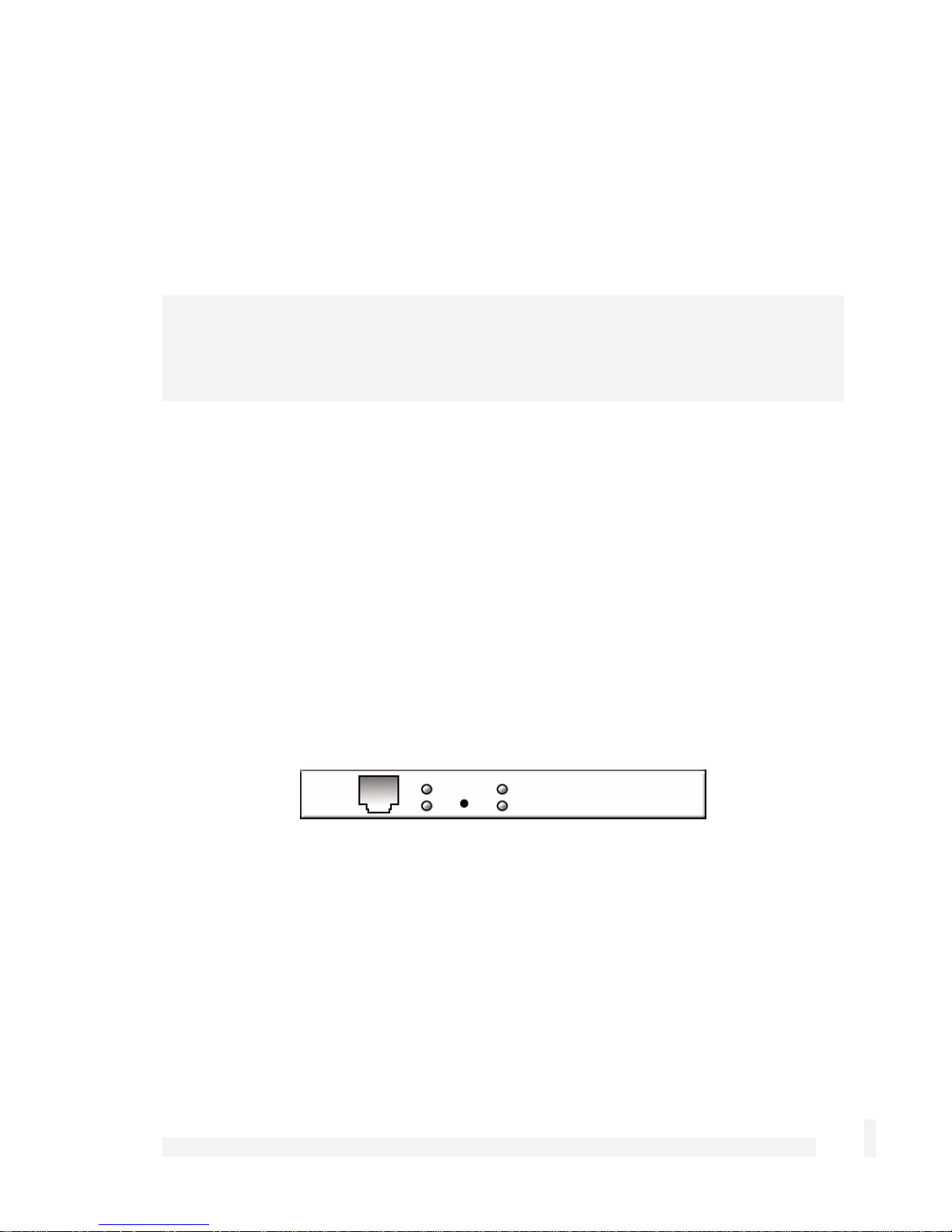
LEDs
The rear panel contains LEDs indicating status. The two LEDs closest to the network
port are network activity (upper) and network link (lower). The two other LEDs are power
(upper) and heart beat (lower).
Introduction
8
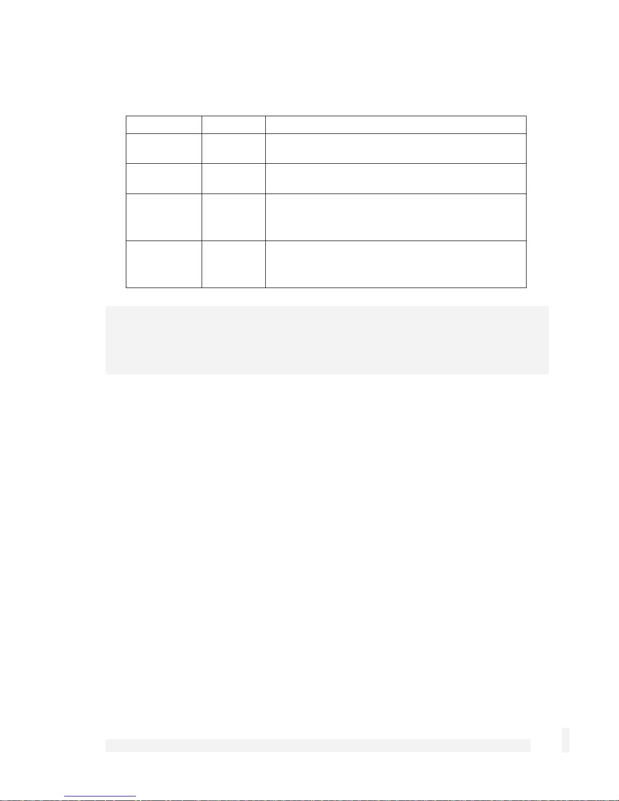
Location Activity Description
Top right
(Power)
Bottom right
(Heart beat)
Top left
(Network
activity)
Bottom left
(Network
link)
Note
If Heart beat does not begin flashing shortly after power is supplied, refer to Appendix D,
Recovering From a Failed Upgrade.
Specifications
On Power is supplied to the CyberGuard SG
appliance (top right).
Flashing The CyberGuard SG appliance is operating
correctly (bottom right).
Flashing Data is being transmitted or received (top left).
On The CyberGuard SG appliance is attached to the
network
Network link
• 10/100baseT Ethernet port
• Ethernet LEDs (link, activity)
Environmental
• Status LEDs: Power, Heart Beat
• Operating temperature between 0° C and 40° C
• Storage temperature between -20° C and 70° C
• Humidity between 0 to 95% (non-condensing)
Introduction
9

Document Conventions
This document uses different fonts and typefaces to show specific actions.
Warning/Note
Text like this highlights important issues.
Bold text in procedures indicates text that you type, or the name of a screen object (e.g.
a menu or button).
Introduction
10

2. Getting Started
This chapter provides step-by-step instructions for installing your CyberGuard SG
appliance. These instructions are identical to those in the printed Quick Install Guide that
shipped with your CyberGuard SG appliance.
Upon completing the steps in this chapter, your
CyberGuard SG gateway or rack mount appliance
is installed in a network configuration similar that
depicted in the figure to the right. If you are
setting up a CyberGuard SG PCI appliance, upon
completing the steps in this chapter, your host PC
is connected securely to your existing LAN.
These instructions assume you have a PC
running Microsoft Windows (95/98/Me/2000/XP
for CyberGuard SG gateway and rack mount
appliances, 2000/XP only for CyberGuard SG PCI
appliances). If you are installing a CyberGuard SG gateway or rack mount appliance,
you must have an Ethernet network interface card installed. You may need to be logged
in with administrator privileges.
Instructions are not given for other operating systems; refer to your operating system
documentation on how to configure your PCs’ network settings using the examples given
for Windows PCs as a guide.
Note
Installing your CyberGuard SG appliance into a well-planned network is easy. However,
network planning is outside the scope of this manual. Please take the time to plan your
network before installing your CyberGuard SG appliance.
• If you are setting up a CyberGuard SG gateway appliance (SG3xx, SG5xx series)
proceed to CyberGuard SG Gateway Appliance Quick Setup.
• If you are setting up a CyberGuard SG rack mount appliance (SG7xx series) proceed
to CyberGuard SG Rack Mount Appliance Quick Setup.
• If you are setting up a CyberGuard SG PCI appliance (SG6xx series), proceed to
CyberGuard SG PCI Appliance Quick Setup.
Getting Started
11

CyberGuard SG Gateway Appliance Quick Setup
Unpack the CyberGuard SG appliance
Check that the following items are included with your CyberGuard SG appliance:
Power adapter
CyberGuard SG CD
Network cable
On the rear panel of the CyberGuard SG appliance you will see network, serial and
possibly USB ports, a Reset/Erase button, and a power inlet.
The front panel of the CyberGuard SG appliance contains activity LEDs (lights) that vary
slightly between models. These provide information on the operating status of the
CyberGuard SG appliance.
Note
Power is ON when power is applied (use only the power adapter packaged with the unit).
System/Heart Beat/TST flashes when the CyberGuard SG appliance is running.
Initially, all appliance models except for the SG300 also have all other front panel LEDs
flashing.
If these LEDs do not behave in this manner before your CyberGuard SG appliance is
attached to the network, perform a factory reset. Press the black Reset/Erase button on
rear panel twice within two seconds to restore factory default settings. If the LEDs are
still not flashing after 30 seconds, you may need to contact customer support.
Set up a single PC to connect to the CyberGuard SG appliance
The CyberGuard SG appliance ships with initial network settings of:
LAN IP address: 192.168.0.1
Getting Started
12

LAN subnet mask: 255.255.255.0
The CyberGuard SG appliance needs an IP address suitable for your LAN before it is
connected. You may choose to use the CyberGuard SG appliance’s initial network
settings above as a basis for your LAN settings.
Connect the supplied power adapter to the CyberGuard SG appliance.
If you are setting up the SG300, attach your PC’s network interface card directly to
any network port on its LAN switch using the supplied network cable.
If you are setting up the SG560, SG565 or SG580, attach your PC’s network interface
card directly any network port on switch A (A1 – A4) using the supplied network
cable.
Otherwise, connect the CyberGuard SG appliance’s LAN network port directly to your
PC’s network interface card using the supplied network cable.
Note
At this point, if you attach the CyberGuard SG appliance directly to a LAN with an existing
DHCP server, or a PC running a DHCP service, it will automatically obtain an additional
address. The CyberGuard SG appliance will still be reachable at 192.168.0.1.
However, we strongly recommend that you do not connect the CyberGuard SG appliance
to your LAN until instructed to do so by this guide.
All other network ports are by default inactive, i.e. they are not running any network
services such as DHCP, and they are not configured with an IP address.
Next, modify your PC’s network settings to enable it to communicate with the
CyberGuard SG appliance.
Click Start -> (Settings ->) Control Panel and double click Network Connections (or in
95/98/Me, double click Network).
Right click on Local Area Connection and select Properties.
Getting Started
13
Note
If there is more than one existing network connection, select the one corresponding to the
network interface card to which the CyberGuard SG appliance is attached.
Select Internet Protocol (TCP/IP) and click Properties (or in 95/98/Me, TCP/IP -> your
network card name if there are multiple entries) and click Properties.
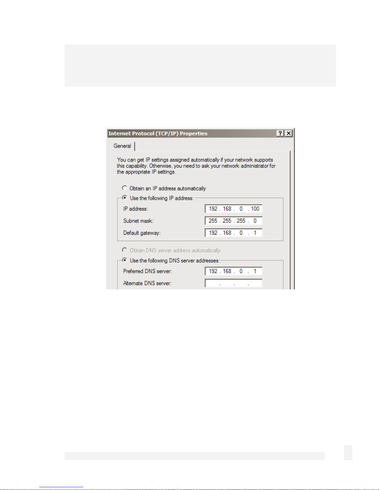
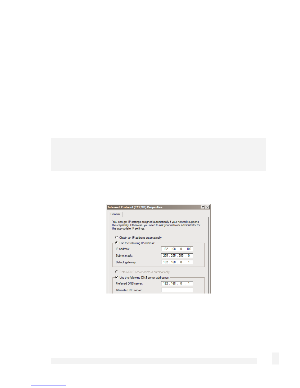
Select Use the following IP address and enter the following details:
IP address: 192.168.0.100
Subnet mask: 255.255.255.0
Default gateway: 192.168.0.1
Select Use the following DNS server addresses and enter:
Preferred DNS server: 192.168.0.1
Getting Started
14
Note
If you wish to retain your existing IP settings for this network connection, click Advanced
and Add the secondary IP address of 192.168.0.100, subnet mask 255.255.255.0.
Set up the CyberGuard SG appliance’s password and LAN connection settings
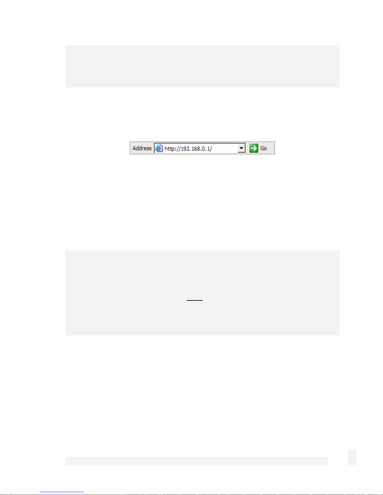
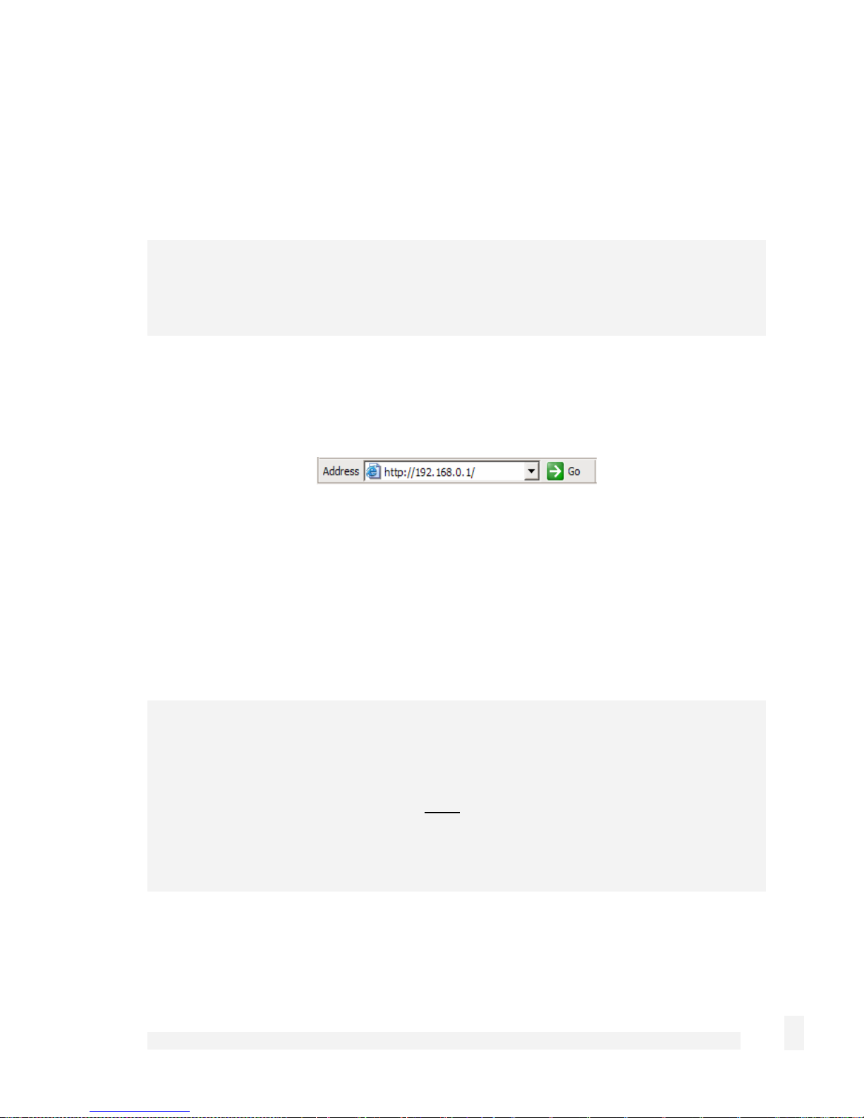
Launch your web browser and navigate to 192.168.0.1.
Select Quick Setup Wizard from the center of the page.
A log in prompt is displayed. Enter the initial user name and password for the
CyberGuard SG appliance:
User name: root
Password: default
Note
If you are unable to browse to the CyberGuard SG appliance at 192.168.0.1, or the initial
username and password are not accepted, press the black Reset/Erase button on the
CyberGuard SG appliance’s rear panel twice, wait 20 – 30 seconds, then try again.
Pressing Reset/Erase twice within 2 seconds resets the CyberGuard SG appliance to its
factory default settings.
Enter and confirm a password for your CyberGuard SG appliance. This is the password
for the user root, the main administrative user account on the CyberGuard SG appliance.
It is therefore important that you choose a password that is hard to guess, and keep it
safe.
Getting Started
15
Note
The new password takes effect immediately. You are prompted to enter it when
completing the next step.
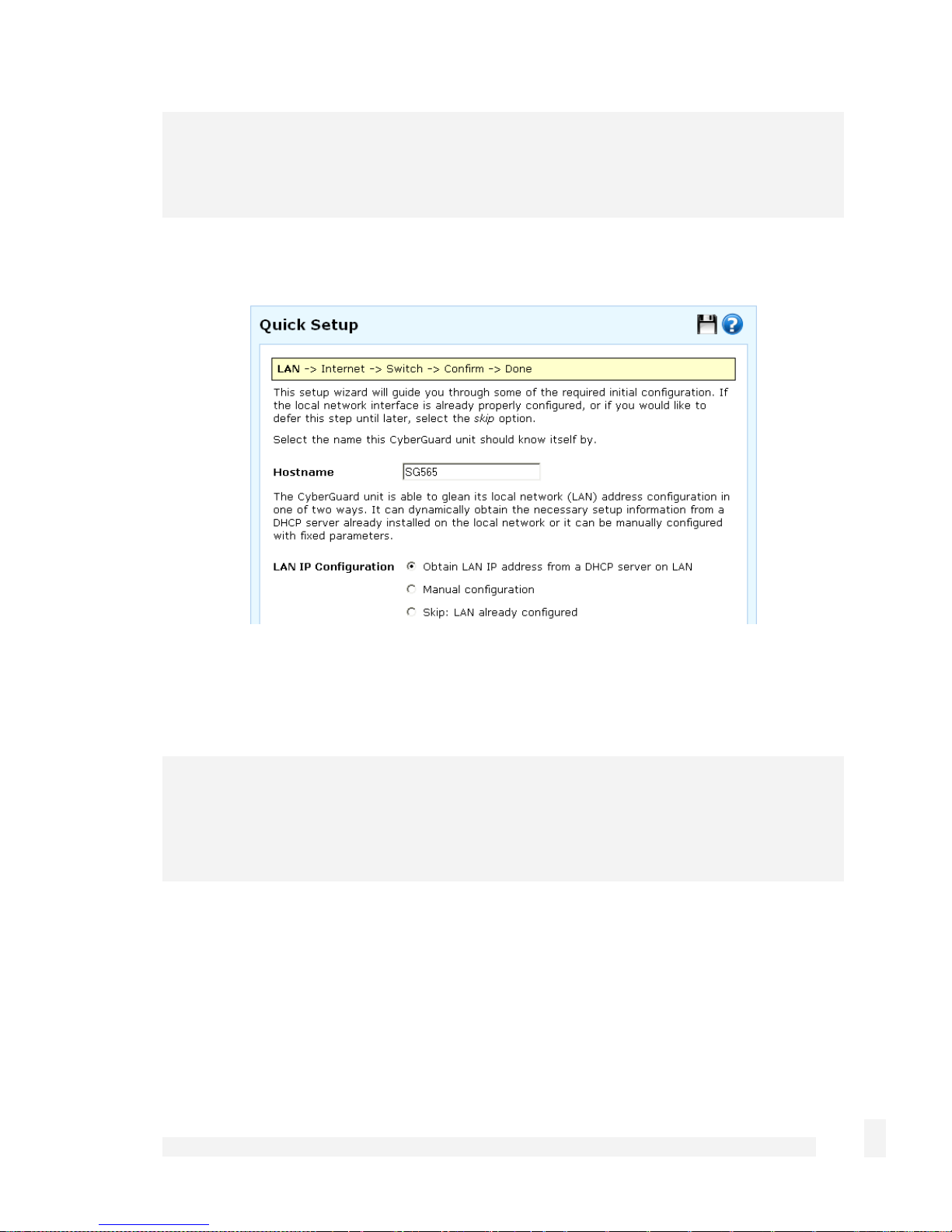
The quick setup wizard is displayed.
Changing the Hostname is not typically necessary.
Select how you would like to set up your LAN connection then click Next.
Note
You must select Manual configuration in order to enable the CyberGuard SG
appliance’s built-in DHCP server. The CyberGuard SG appliance’s DHCP server
automatically configures the network settings of PCs and other hosts on your LAN.
Changes to the CyberGuard SG appliance’s LAN configuration do not take effect until the
quick setup wizard has completed.
Select Manual configuration to manually specify the CyberGuard SG appliance’s
LAN connection settings (recommended).
Getting Started
16
Select Skip: LAN already configured if you wish to use the CyberGuard SG
appliance’s initial network settings (IP address 192.168.0.1 and subnet mask
255.255.255.0) as a basis for your LAN settings, and you do not wish to use the
CyberGuard SG appliance’s built-in DHCP server. Skip to the next step.
You may choose to Obtain LAN IP address from a DHCP server on LAN if you
have an existing DHCP server, and wish to rely on it to automatically configure the
CyberGuard SG appliance’s LAN connection settings (not recommended). Skip to the
next step.
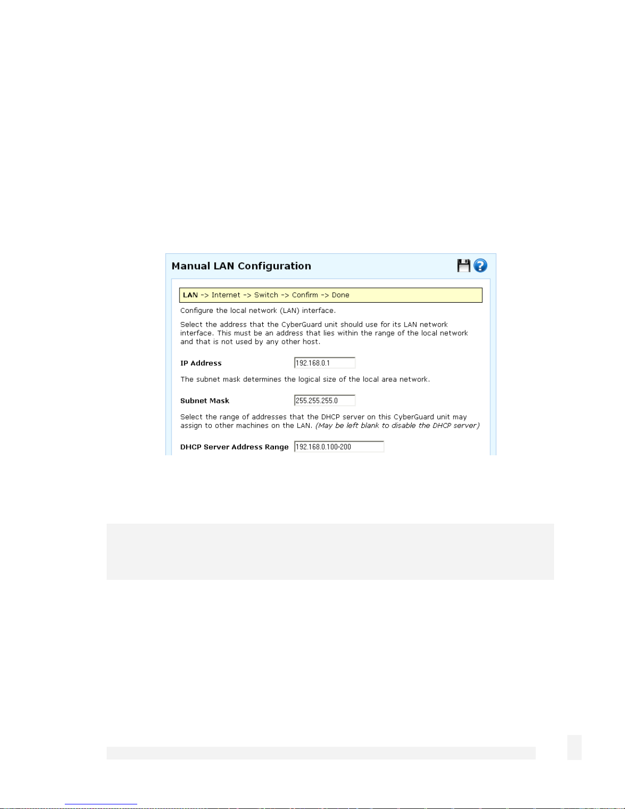
If you selected Manual configuration, some additional information is required.
Otherwise, skip to the next step.
Enter an IP address and Subnet Mask for the CyberGuard SG appliance’s LAN
connection.
Note
Take note of this IP address and subnet mask, as you will need them later on.
To enable the CyberGuard SG appliance’s built-in DHCP server, enter a range of
addresses to hand out in DHCP Server Address Range. PCs and other hosts on your
LAN that are set to automatically obtain network settings are assigned an address from
this range, and instructed to use the CyberGuard SG appliance as their gateway to the
Internet and as their DNS server for Internet domain name resolution.
Click Next.
Getting Started
17
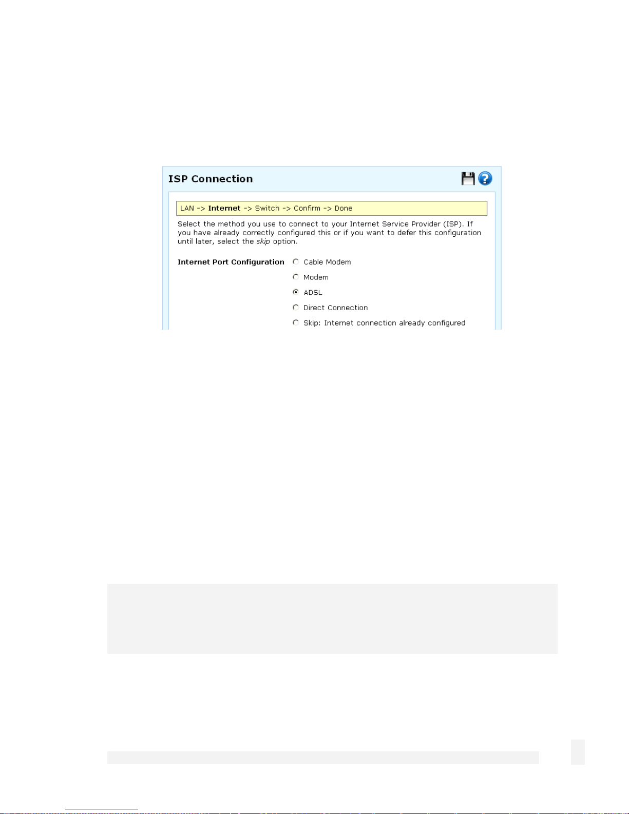
Set up the CyberGuard SG appliance’s Internet connection settings
First, attach the CyberGuard SG appliance to your modem device or Internet connection
medium. If necessary, give the modem device some time to power up.
Select your Internet connection type and click Next. The options displayed differ
depending on the connection type selected.
If you are connecting using a Cable Modem, select your ISP, or Generic Cable
Modem Provider if yours does not appear.
If you are connecting using an analog (dialup) Modem, enter the details provided by
your ISP.
If you are connecting using an ADSL modem, select Auto detect ADSL connection
type, click Next, then enter the details provided by your ISP. If auto detection fails,
you must manually select your ADSL connection type – if you are unsure of this,
contact your ISP.
If you have a Direct Connection to the Internet (e.g. a leased line), enter the IP
settings provided by your ISP.
Note
For detailed help for each of these options, please refer to the user manual on the
CyberGuard SG CD (\doc\UserManual.pdf).
After entering the appropriate details, click Next.
Getting Started
18
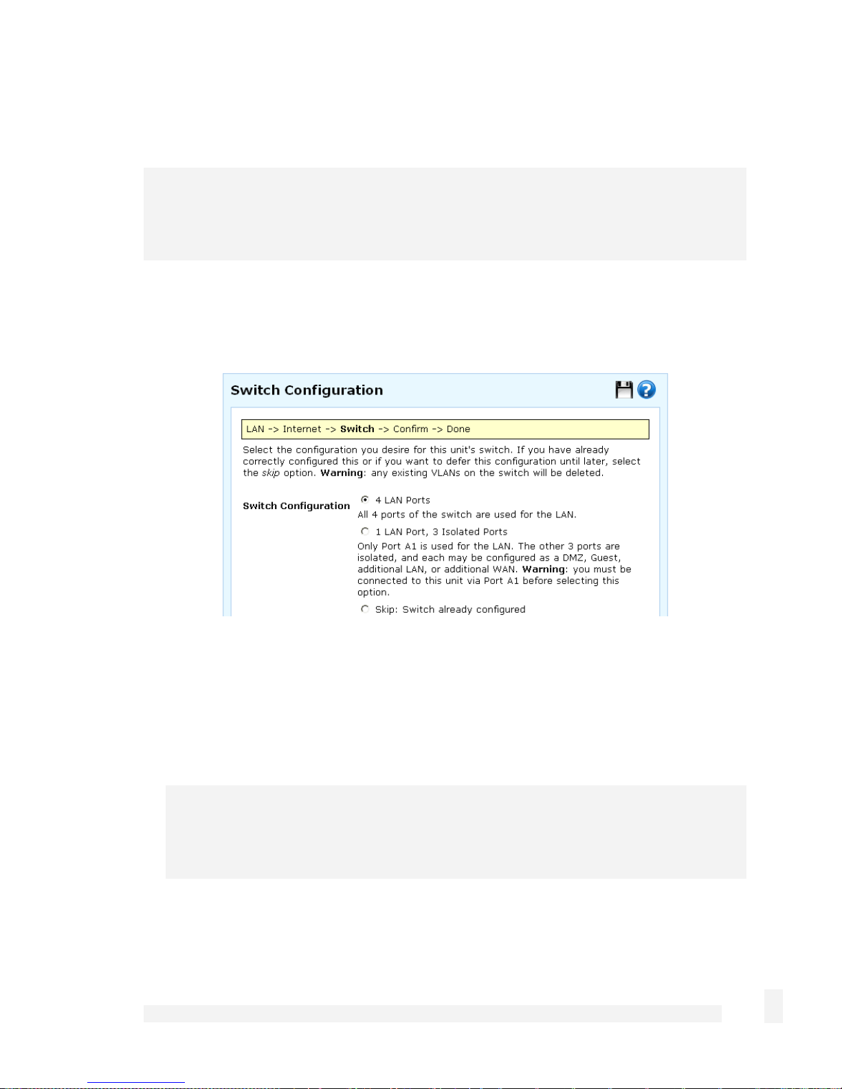
Set up the CyberGuard SG appliance’s switch
Note
This page will only display if you are setting up the SG560, SG565 or SG580. Otherwise
skip to the next step.
By default, the CyberGuard SG appliance’s switch A behaves as a conventional
switching hub. However, it may be configured so that each port behaves as if it were
physically separate from the others.
Select a configuration for the CyberGuard SG appliance’s switch then click Next.
Select 1 LAN Port, 3 Isolated Ports if you require multiple network segments, such
as a DMZ, guest network or second LAN, or if you want to use multiple broadband
Internet connections for Internet load balancing or Internet failover. Port A1 is used
as the primary LAN connection.
Note
For instructions on setting up multiple network segments and Internet connections,
please refer to the next chapter of this manual.
Otherwise, select 4 LAN Ports.
Getting Started
19

Connect the CyberGuard SG appliance to your LAN
Review your configuration changes. Once you are satisfied, click Finish to activate the
new configuration.
Note
If you have changed the CyberGuard SG appliance’s LAN connection settings, it may
become uncontactable at this point. This step describes how to set up the PCs on your
network to access the CyberGuard SG appliance and the Internet.
Connect the CyberGuard SG appliance to your LAN if you haven’t already done so.
If you are setting up the SG300, connect PCs and/or your LAN hub directly to its LAN
switch.
If you are setting up the SG560, SG565 or SG580 and have configured its switch as 4
LAN Ports, connect PCs and/or your LAN hub directly to switch A.
If you are setting up the SG560, SG565 or SG580 and have configured its switch as 1
LAN Port, 3 Isolated Ports, connect port A1 directly to your LAN hub.
Otherwise, connect the LAN port directly to your LAN hub.
Set up your LAN to access the Internet
To access the Internet, each PC on your LAN must be assigned an appropriate IP
address, and have the CyberGuard SG appliance’s LAN IP address designated as its
gateway and as its DNS server.
A DHCP server allows PCs to automatically obtain these network settings when they start
up. If your network does not have a DHCP server, you may either manually set up each
PC on your network, or set up the CyberGuard SG appliance's DHCP server.
To use the CyberGuard SG appliance’s built-in DHCP server (recommended),
proceed to Automatic configuration of your LAN.
If your LAN already has a DHCP server that you will use instead of the CyberGuard
SG appliance’s built-in DHCP server, proceed to Automatic configuration of your LAN
using an existing DHCP server.
Getting Started
20
If you do not want to use a DHCP server, proceed to Manual configuration of your
LAN.
Automatic configuration of your LAN
By selecting Manual Configuration for the CyberGuard SG appliance’s LAN connection,
and supplying DHCP Server Address Range, the CyberGuard SG appliance’s DHCP
server is already set up and running.
Each PC on your LAN must now be set up to automatically obtain network settings.
Click Start -> (Settings ->) Control Panel and double click Network Connections (or in
95/98/Me, double click Network).
If presented with multiple connections, right click on Local Area Connection (or
appropriate network connection) and select Properties.
Select Internet Protocol (TCP/IP) and click Properties (or in 95/98/Me, TCP/IP -> [your
network card name] if there are multiple entries) and click Properties (in 95/98/Me, you
may also have to click the IP Address tab).
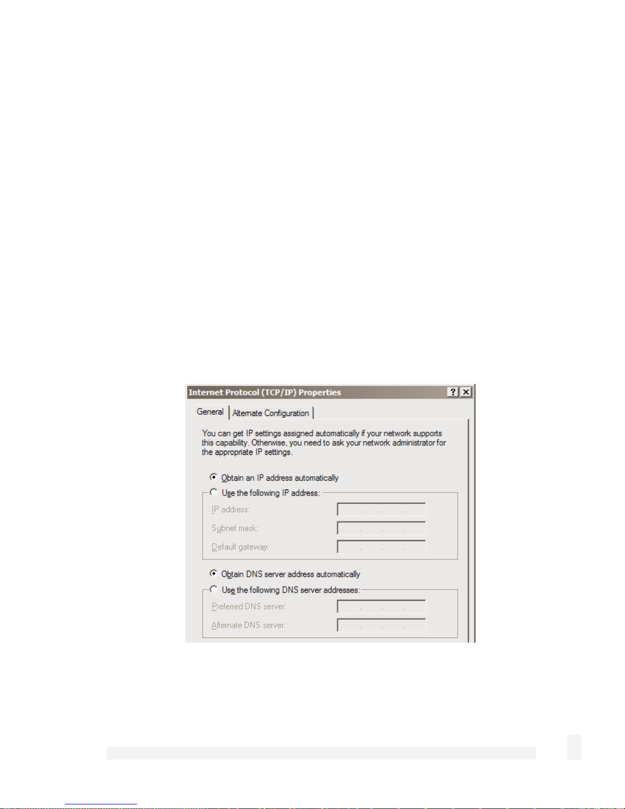
Check Obtain an IP address automatically, check Obtain DNS server address
automatically and click OK (in 95/98/Me, reboot the PC if prompted to do so).
Getting Started
21

Quick setup is now complete.
Automatic configuration of your LAN using an existing DHCP server
If you chose to have the CyberGuard SG appliance Obtain LAN IP address from a
DHCP server on LAN, It is strongly recommended that you add a lease to your
existing DHCP server to reserve the IP address you chose for the CyberGuard SG
appliance’s LAN connection.
If you chose to set the CyberGuard SG appliance’s LAN connection settings using
Manual configuration, you may simply remove this address from the pool of
available addresses.
Enter this same IP address as the gateway IP address to be handed out by the existing
DHCP server.
Enter this same IP address as the DNS server IP address to be handed out by the DHCP
server.
Ensure all PCs on the network are set up to automatically obtain network configuration as
per Automatic configuration of your LAN, then restart them.
Note
The purpose of restarting the computers is to force them to update their automatically
configured network settings. Alternatively you can use a utility such as ipconfig to
release then renew the DHCP lease, or disable and re-enable the network connection.
Quick setup is now complete.
Manual configuration of your LAN
Click Start -> (Settings ->) Control Panel and double click Network Connections (or in
95/98/Me, double click Network).
If presented with multiple connections, right click on Local Area Connection (or
appropriate network connection) and select Properties.
Select Internet Protocol (TCP/IP) and click Properties (or in 95/98/Me, TCP/IP -> [your
network card name] if there are multiple entries).
Getting Started
22

Enter the following details:
IP address is an IP address that is part of the same subnet range as the CyberGuard
SG appliance’s LAN connection (if using the default settings, 192.168.0.2 –
192.168.0.254).
Subnet mask is the subnet mask of the CyberGuard SG appliance’s LAN connection
(if using the default settings, 255.255.255.0).
Default gateway is the IP address of the CyberGuard SG appliance’s LAN
connection (if using the default settings, 192.168.0.1).
Preferred DNS server is the IP address of the CyberGuard SG appliance’s LAN
connection (if using the default settings, 192.168.0.1).
Click OK (or in 95/98/Me, Add then OK, reboot the PC if prompted to do so).
Perform these steps for each PC on your network.
Quick setup is now complete.
CyberGuard SG Rack Mount Appliance Quick Setup
Unpack the CyberGuard SG appliance
Check that the following items are included with your CyberGuard SG appliance:
Power cable
CyberGuard SG CD
Network cable
The front panel of the CyberGuard SG appliance has two 4- port network switches (A and
B), two network ports (C and D), a serial port, status LEDs and Erase button.
The rear panel of the CyberGuard SG appliance has a power inlet and power switch.
Note
Additionally, the SG710+ has two gigabit network ports on the rear panel (E and F).
Getting Started
23

The status LEDs on the front panel provide information on the operating status of the
CyberGuard SG appliance.
Note
Power is ON when power is applied. H/B (heart beat) flashes when the CyberGuard SG
appliance is running. Each of the network ports has two LEDs indicating link, activity and
speed. In its factory default state, the four status LEDs next to Power flash.
If these LEDs do not behave in this manner before your CyberGuard SG appliance is
attached to the network, perform a factory reset. Press the black Erase button on front
panel twice within two seconds to restore factory default settings. If the LEDs are still not
flashing after 30 seconds, you may need to contact customer support.
Set up a single PC to connect to the CyberGuard SG appliance
The CyberGuard SG appliance ships with initial network settings of:
LAN IP address: 192.168.0.1
LAN subnet mask: 255.255.255.0
The CyberGuard SG appliance needs an IP address suitable for your LAN before it is
connected. You may choose to use the CyberGuard SG appliance’s initial network
settings above as a basis for your LAN settings.
Note
Initial configuration is performed through a port on network switch A (A1 – A4). If you
attach A1 – A4 directly to a LAN with an existing DHCP server, or a PC running a DHCP
service, it will automatically obtain an additional address. The CyberGuard SG appliance
will still be reachable at 192.168.0.1.
However, we strongly recommend that you do not connect the CyberGuard SG appliance
to your LAN until instructed to do so by this guide.
All other network ports are by default inactive, i.e. they are not running any network
services such as DHCP, and they are not configured with an IP address.
Getting Started
24
Connect the supplied power cable to the power inlet on the rear panel of the CyberGuard
SG appliance and turn on the rear panel power switch.
Connect one of the ports of network switch A (A1 – A4) directly to your PC’s network
interface card using the supplied network cable.
Next, modify your PC’s network settings to enable it to communicate with the
CyberGuard SG appliance.
Click Start -> (Settings ->) Control Panel and double click Network Connections (or in
95/98/Me, double click Network).
Right click on Local Area Connection and select Properties.
Note
If there is more than one existing network connection, select the one corresponding to the
network interface card to which the CyberGuard SG appliance is attached.
Select Internet Protocol (TCP/IP) and click Properties (or in 95/98/Me, TCP/IP -> your
network card name if there are multiple entries) and click Properties.
Select Use the following IP address and enter the following details:
IP address: 192.168.0.100
Subnet mask: 255.255.255.0
Getting Started
25
Default gateway: 192.168.0.1
Select Use the following DNS server addresses and enter:
Preferred DNS server: 192.168.0.1
Note
If you wish to retain your existing IP settings for this network connection, click Advanced
and Add the secondary IP address of 192.168.0.100, subnet mask 255.255.255.0.
Set up the CyberGuard SG appliance’s password and LAN connection settings
Launch your web browser and navigate to 192.168.0.1.
Select Quick Setup Wizard from the center of the page.
A log in prompt is displayed. Enter the initial user name and password for the
CyberGuard SG appliance:
User name: root
Password: default
Note
If you are unable to browse to the CyberGuard SG appliance at 192.168.0.1, or the initial
username and password are not accepted, press the black Erase button on the
CyberGuard SG appliance’s front panel twice, wait 20 – 30 seconds, then try again.
Pressing Erase twice within 2 seconds resets the CyberGuard SG appliance to its factory
default settings.
Getting Started
26

Enter and confirm a password for your CyberGuard SG appliance. This is the password
for the user root, the main administrative user account on the CyberGuard SG appliance.
It is therefore important that you choose a password that is hard to guess, and keep it
safe.
Note
The new password takes effect immediately. You are prompted to enter it when
completing the next step.
The quick setup wizard is displayed.
Changing the Hostname is not typically necessary.
Select how you would like to set up your LAN connection then click Next.
Note: You must select Manual configuration in order to enable the CyberGuard SG
appliance’s built-in DHCP server. The CyberGuard SG appliance’s DHCP server
automatically configures the network settings of PCs and other hosts on your LAN.
Changes to the CyberGuard SG appliance’s LAN configuration do not take effect until the
quick setup wizard has completed.
Select Manual configuration to manually specify the CyberGuard SG appliance’s
LAN connection settings (recommended).
Getting Started
27

Select Skip: LAN already configured if you wish to use the CyberGuard SG
appliance’s initial network settings (IP address 192.168.0.1 and subnet mask
255.255.255.0) as a basis for your LAN settings, and you do not wish to use the
CyberGuard SG appliance’s built-in DHCP server. Skip to the next step.
You may choose to Obtain LAN IP address from a DHCP server on LAN if you
have an existing DHCP server, and wish to rely on it to automatically configure the
CyberGuard SG appliance’s LAN connection settings (not recommended). Skip to the
next step.
If you selected Manual configuration, some additional information is required.
Otherwise, skip to the next step.
Enter an IP address and Subnet Mask for the CyberGuard SG appliance’s LAN
connection.
Note
Take note of this IP address and subnet mask, as you will need them later on.
To enable the CyberGuard SG appliance’s built-in DHCP server, enter a range of
addresses to hand out in DHCP Server Address Range. PCs and other hosts on your
LAN that are set to automatically obtain network settings are assigned an address from
this range, and instructed to use the CyberGuard SG appliance as their gateway to the
Internet and as their DNS server for Internet domain name resolution.
Click Next.
Getting Started
28

Connect the CyberGuard SG appliance to your LAN
Review your configuration changes. Once you are satisfied, click Finish to activate the
new configuration.
Note
If you have changed the CyberGuard SG appliance’s LAN connection settings, it may
become uncontactable at this point. This step describes how to set up the PCs on your
network to access the CyberGuard SG appliance and the Internet.
Connect PCs and/or your LAN hub to switch A on the CyberGuard SG appliance.
Set up the PCs on your LAN
Each PC on your LAN must now be assigned an appropriate IP address, and have the
CyberGuard SG appliance’s LAN IP address designated as its gateway and as its DNS
server.
A DHCP server allows PCs to automatically obtain these network settings when they start
up. If your network does not have a DHCP server, you may either manually set up each
PC on your network, or set up the CyberGuard SG appliance's DHCP server.
To use the CyberGuard SG appliance’s built-in DHCP server (recommended),
proceed to Automatic configuration of your LAN.
If your LAN already has a DHCP server that you will use instead of the CyberGuard
SG appliance’s built-in DHCP server, proceed to Automatic configuration of your LAN
using an existing DHCP server.
If you do not want to use a DHCP server, proceed to Manual configuration of your
LAN.
Automatic configuration of your LAN
By selecting Manual Configuration for the CyberGuard SG appliance’s LAN connection,
and supplying DHCP Server Address Range, the CyberGuard SG appliance’s DHCP
server is already set up and running.
Each PC on your LAN must now be set up to automatically obtain network settings.
Getting Started
29

Click Start -> (Settings ->) Control Panel and double click Network Connections (or in
95/98/Me, double click Network).
If presented with multiple connections, right click on Local Area Connection (or
appropriate network connection) and select Properties.
Select Internet Protocol (TCP/IP) and click Properties (or in 95/98/Me, TCP/IP -> [your
network card name] if there are multiple entries) and click Properties (in 95/98/Me, you
may also have to click the IP Address tab).
Check Obtain an IP address automatically, check Obtain DNS server address
automatically and click OK (in 95/98/Me, reboot the PC if prompted to do so).
Automatic configuration of your LAN using an existing DHCP server
If you chose to have the CyberGuard SG appliance Obtain LAN IP address from a
DHCP server on LAN, It is strongly recommended that you add a lease to your
existing DHCP server to reserve the IP address you chose for the CyberGuard SG
appliance’s LAN connection.
If you chose to set the CyberGuard SG appliance’s LAN connection settings using
Manual configuration, you may simply remove this address from the pool of
available addresses.
Getting Started
30

Enter this same IP address as the gateway IP address to be handed out by the existing
DHCP server.
Enter this same IP address as the DNS server IP address to be handed out by the DHCP
server.
Ensure all PCs on the network are set up to automatically obtain network configuration as
per Automatic configuration of your LAN, then restart them.
Note
The purpose of restarting the computers is to force them to update their automatically
configured network settings. Alternatively you can use a utility such as ipconfig to
release then renew the DHCP lease, or disable and re-enable the network connection.
Manual configuration of your LAN
Click Start -> (Settings ->) Control Panel and double click Network Connections (or in
95/98/Me, double click Network).
If presented with multiple connections, right click on Local Area Connection (or
appropriate network connection) and select Properties.
Select Internet Protocol (TCP/IP) and click Properties (or in 95/98/Me, TCP/IP -> [your
network card name] if there are multiple entries).
Enter the following details:
IP address is an IP address that is part of the same subnet range as the CyberGuard
SG appliance’s LAN connection (e.g. if using the default settings, 192.168.0.2 –
192.168.0.254).
Subnet mask is the subnet mask of the CyberGuard SG appliance’s LAN connection
(if using the default settings, 255.255.255.0).
Default gateway is the IP address of the CyberGuard SG appliance’s LAN
connection (if using the default settings, 192.168.0.1).
Preferred DNS server is the IP address of the CyberGuard SG appliance’s LAN
connection (if using the default settings, 192.168.0.1).
Click OK (or in 95/98/Me, Add then OK, reboot the PC if prompted to do so).
Getting Started
31

Perform these steps for each PC on your network.
Set up the CyberGuard SG appliance’s Internet connection settings
Choose a port on the CyberGuard SG appliance for your primary Internet connection.
Port C is used in this guide. Attach Port C to your modem device or Internet connection
medium. If necessary, give the modem device some time to power up.
Note
If you have changed the CyberGuard SG appliance’s LAN connection settings, browse to
the new LAN IP address.
Select Network Setup from the Network Setup menu.
In the row labeled Port C, select your Internet connection type from the Change Type
drop down list.
If you are connecting using a Cable Modem, select your ISP, or Generic Cable
Modem Provider if yours does not appear.
If you are connecting using an ADSL modem, select Auto detect ADSL connection
type, click Next, then enter the details provided by your ISP. If auto detection fails,
you must manually select your ADSL connection type – if you are unsure of this,
contact your ISP.
If you have a Direct Connection to the Internet (e.g. a leased line), enter the IP
settings provided by your ISP.
Getting Started
32

Note
For detailed help for each of these options, please refer to the next chapter.
After entering the appropriate details, click Finish.
Quick setup is now complete.
CyberGuard SG PCI Appliance Quick Setup
Unpack the CyberGuard SG appliance
Check that the CyberGuard SG CD is included with your appliance:
On the CyberGuard SG appliance is a single 10/100 network port, a Reset button and
four LEDs (lights). The LEDs provide information on the operating status of your
CyberGuard SG appliance. The two LEDs closest to the network port indicate network
link and network activity.
The two LEDs furthest from the network port indicate Power and Heart Beat. The Heart
Beat LED blinks when the CyberGuard SG appliance is running. The Power LED is ON
when power is applied.
Install the CyberGuard SG appliance in an unused PCI slot
Power off your PC and remove its cover.
Select an unused PCI slot and insert the CyberGuard SG appliance.
Power on your PC.
Install the network driver on your PC
The CyberGuard SG appliance is automatically detected and the appropriate driver is
installed when Windows starts up. It is detected as a Realtek RTL8139-series Fast
Ethernet Adapter.
Getting Started
33

Note
You can check that a new network adapter has been installed by clicking Start ->
(Settings ->) Network and Dialup Connections -> Local Area Connection (possibly
followed by a number) -> Properties and ensure the adapter is listed in the Connect
using field.
Set up your PC to connect to the web management console
Note
The following steps assume you want to set up your CyberGuard SG appliance in
bridged mode, so that it sits between your PC and the LAN, transparently filtering
network traffic.
If you want to set up your CyberGuard SG appliance for NAT mode or to connect directly
to your ISP, refer to the User Manual on the CyberGuard SG CD (\doc\UserManual.pdf).
The CyberGuard SG appliance ships with initial network settings of:
IP address: 192.168.0.1
Subnet mask: 255.255.255.0
Next, modify your PC’s network settings to enable it to communicate with the
CyberGuard SG appliance.
Click Start -> (Settings ->) Control Panel and double click Network Connections.
Right click on Local Area Connection (or appropriate network connection for the newly
installed PCI appliance) and select Properties.
Select Internet Protocol (TCP/IP) and click Properties.
Getting Started
34

Select Use the following IP address and enter the following details:
IP address: 192.168.0.100
Subnet mask: 255.255.255.0
Leave the Default gateway and DNS server addresses blank.
Set up the CyberGuard SG appliance’s password and network connection settings
Launch your web browser and navigate to 192.168.0.1.
Select Network Setup from the Networking menu.
A log in prompt is displayed. Enter the initial user name and password for the
CyberGuard SG appliance:
User name: root
Password: default
Note
If you are unable to connect to the management console at 192.168.0.1, or the initial
username and password are not accepted, press the Reset button on the CyberGuard
SG appliance’s rear panel twice, wait 20 – 30 seconds, and try again.
Getting Started
35

Pressing Reset twice within 2 seconds resets the CyberGuard SG appliance to its factory
default settings
Enter and confirm a password for your CyberGuard SG appliance. This is the password
for the user root, the main administrative user account on the CyberGuard SG appliance.
It is therefore important that you choose a password that is hard to guess, and keep it
safe.
Note
The new password takes effect immediately. You are prompted to enter it when
completing the next step.
In the row labeled Bridge, click the Modify icon.
Note
The purpose of this step is to configure the IP address for the web management console.
For convenience, this is generally a free IP address on your LAN.
If your LAN has a DHCP server running, you may set up the CyberGuard SG
appliance and your PC to obtain their network settings automatically. Proceed to
Automatic configuration.
Otherwise, you must manually specify network settings for both the CyberGuard SG
appliance and your PC. Proceed to Manual configuration.
Automatic configuration
Before continuing, ensure your DHCP server has two free leases. One is used for the
web management console, the other for your PC.
Note
It is strongly recommended that you reserve the IP address to be used by the web
management console using the CyberGuard SG appliance’s MAC address. In bridged
mode, this is the top MAC address of the three displayed on the CyberGuard SG
appliance itself.
Getting Started
36

Check DHCP assigned. Anything in the IP Address and Subnet Mask fields is ignored.
Click Update.
Click Start -> (Settings ->) Control Panel and double click Network Connections.
Right click on Local Area Connection (or appropriate network connection for the newly
installed PCI appliance) and select Properties.
Select Internet Protocol (TCP/IP) and click Properties and click Properties.
Getting Started
37

Check Obtain an IP address automatically, check Obtain DNS server address
automatically and click OK.
Attach your CyberGuard SG appliance’s Ethernet port to your LAN’s hub or switch.
Quick setup is now complete.
Manual configuration
Ensure you have two free IP addresses that are part of the subnet range of your LAN,
and ensure you know your LAN’s subnet mask, and the DNS server address and
gateway address used by PCs on your LAN.
Note
Contact your network administrator if you are unsure of any of these settings.
The first IP address is used by the web management console
Getting Started
38

Enter this address as the IP Address, and the subnet mask for your LAN as the Subnet
mask.
Ensure DHCP assigned is unchecked.
You may also enter one or more DNS Server(s) and a Gateway address to be used by
the CyberGuard SG appliance, not your PC, for access to the Internet. Typically this is
not necessary, as only your PC needs to access the Internet.
Click Update.
Next, configure your PC with the second IP address in the same manner you would as if
it were connected to the LAN with a regular network interface card.
Click Start -> (Settings ->) Control Panel and double click Network Connections.
Right click on Local Area Connection (or appropriate network connection for the newly
installed PCI appliance) and select Properties.
Select Internet Protocol (TCP/IP) and click Properties.
Getting Started
39

Enter the following details:
IP address is the second free IP addresses that is part of the subnet range of your
LAN.
Subnet mask is the subnet mask of your LAN.
Default gateway is the IP address of your LAN’s default gateway.
Preferred DNS server is the IP address of the DNS server used by PCs on your
LAN.
Click OK.
Attach your CyberGuard SG appliance’s Ethernet port to your LAN’s hub.
Quick setup is now complete.
Disabling the reset button on your CyberGuard SG PCI appliance
For convenience, the CyberGuard SG appliance ships with the rear panel Reset button
enabled. This allows the CyberGuard SG appliance’s configuration to be reset to factory
defaults.
Getting Started
40

From a network security standpoint, it may be desirable to disable the Reset switch after
initial setup has been performed. This is accomplished by removing the jumper linking
CON2 on the CyberGuard SG appliance. This jumper is labeled Remove Link to Disable
Erase.
The CyberGuard SG Management Console
The various features of your CyberGuard SG appliance are configured and monitored
using the management console. Follow the steps from the beginning of this chapter to
set up your PC to access the management console.
The main menu is displayed on the left hand side. Navigate your way around and get a
feel for the CyberGuard SG appliance’s features by clicking the corresponding link in the
main menu.
The remainder of this user manual is roughly divided into
chapters based on the main menu section heading, e.g.
Network Setup, Firewall, etc. Chapter sections roughly
correspond to the menu items under each heading, e.g. DHCP
Server, Web Cache.
Help
To access help for the current page, click the blue help icon on the top right hand side of
the.screen.
Each field is described, along with acceptable input values where appropriate. To search
the entire contents of the help system, enter search Keywords and click Search.
Getting Started
41

Backup/restore configuration
Hover your mouse over the black backup/restore icon on the top right hand side of the
screen to display the date on which configuration changes were last backed up. Click the
icon to backup or restore backed up configuration; see the Backup/Restore section of the
chapter entitled System for details.
Getting Started
42

3. Network Setup
This chapter describes the Network Setup sections of the web management console.
Here you can configure each of your CyberGuard SG appliance’s Ethernet, wireless and
serial ports. It is accessed by clicking Network Setup under the Network Setup section
of the main web management console menu.
The QoS Traffic Shaping and IPv6 sections are also described towards the end of this
chapter.
An Ethernet network interface may be configured to connect to your LAN, DMZ, an
untrusted LAN, or the Internet as a primary, back-up or load-balacing connection. A
serial port may be configured to provide remote dial-in access, or connect to the Internet
as a primary or back-up connection. A wireless interface may be configured to connect
to your LAN, DMZ or an untrusted LAN.
If you are using a CyberGuard SG gateway or rack mount appliance, the section Set up
the PCs on your LAN to access the Internet in the chapter entitled Getting Started
describes how to configure the PCs on your LAN to share the connection once your
Internet connection has been established.
Configuring Connections
Under the Connections tab, each of your CyberGuard SG appliance’s network interfaces
is displayed, alongside its physical Port name and the Current Details of its
configuration.
Initially, all network interfaces are unconfigured, aside from a single LAN connection on
the initial setup port (switch A on CyberGuard SG rack mount appliances, SG560, SG565
and SG580, the LAN port on other models).
Network Setup
43

A network interface is configured by selecting a connection type from the Change Type
pull down menu. The current configuration can be viewed or modified by clicking the Edit
icon. Clicking the Delete icon unconfigures a network interface; you are prompted to
confirm this action.
Multifunction vs. Fixed-function Ports
Some CyberGuard SG appliances have network ports with labels corresponding to the
port’s function, i.e. LAN, DMZ and Internet/WAN. These are said to be fixed-function
ports.
Alternatively, some CyberGuard SG appliances have network ports that are generically
labeled, e.g. port A, port B, port C. These are said to be multifunction ports. This reflects
the ability of these ports to perform many different functions, e.g. port B is not limited to
connecting to the Internet only, it may be configured as a LAN connection.
Note
Before beginning configuration of multifunction ports, you should determine which
function you are assigning to each of the ports.
Proceed to the section pertaining to your CyberGuard SG appliance for information on its
network ports and possible configurations.
SG710, SG710+: Multifunction Switches and Ports
CyberGuard SG rack mount appliances have a fixed-function LAN switch (switch A), and
a multifunction switch (switch B) and two or four multifunction Ethernet ports (C, D, E and
F).
Network Setup
44

Note
The switches’ ports can not be configured individually; a switch is configured with a single
function only (e.g., LAN switch, DMZ switch).
SG560, SG565 and SG580: Multifunction Ports
The CyberGuard SG560, SG565 and SG580 have generically named Ethernet ports
(ports A1, A2, A3, A4 and B). By default, switch A functions as a regular LAN switch,
with network traffic passing freely between its ports. Typically, port B is used as your
primary Internet connection.
However, switch A’s ports can be configured individually to perform separate functions,
e.g. port A2 can be a configured to connect to a second LAN, port A3 can be configured
as a DMZ port, and port A4 can be configured as a secondary Internet connection.
These per-port configuration scenarios are accomplished using VLANs (virtual local area
networks). For documentation concerning the advanced use of the VLAN capability of
your CyberGuard SG appliance, refer to the sections entitled VLANs and Port based
VLANs towards the end of this chapter.
All Other SG Models: Fixed-function Ports
All other CyberGuard SG appliances have specifically labeled ports for specific functions.
The port labeled LAN may only perform the functions described in the section entitled
LAN Connection, the port labeled Internet or WAN may only perform the functions
described in the section entitled Internet Connection.
Note
On SG570 and SG575 models, the DMZ port is special in that it may be configured with
any kind of connection, i.e. LAN, DMZ, Guest or Internet. These connection types are
discussed during the course of this chapter.
Network Setup
45

Direct Connection
A direct connection is a direct IP connection to a network, i.e. a connection that does not
require a modem to be established. This is typically a LAN, DMZ or Guest connection,
but may also be an Internet connection. Network settings may be assigned statically, or
dynamically by a DHCP server.
Note
Direct connections may be added to a network bridge, this is discussed in Bridging later
in this chapter.
Network settings
Click the Edit icon of the interface your wish to modify.
To assign network settings statically, enter an IP Address and Subnet Mask. If you are
using the CyberGuard SG appliance in its default, network address translation mode,
(see Network address translation in the Advanced section of this chapter), this is typically
part of a private IP range, such as 192.168.0.1 / 255.255.255.0. Ensure DHCP assigned
is unchecked.
If required, enter a default Gateway out which to send outgoing traffic on this connection.
For LAN connections, a default gateway is not generally necessary.
Network Setup
46

To have your CyberGuard SG appliance obtain its LAN network settings from an active
DHCP server on your local network, check DHCP assigned. Note that anything in the IP
Address,Subnet Mask and Gateway fields are ignored.
You may also enter one or more DNS servers. Multiple servers may be entered
separated by commas.
Firewall class
The Firewall class setting controls the basic allow/deny policy for this interface. Allowed
network traffic is accepted, denied network traffic is dropped; this means network traffic is
denied silently, no response such as “connection refused” is sent back to the originator of
the traffic.
The following table details the policy associated with each firewall class. Note that VPN
and Dial-In connections are by default assigned a firewall class of LAN.
Incoming Interface Outgoing Interface Action
LAN Any Accept
VPN Any Accept
Dialin Any Accept
DMZ Internet Accept
DMZ Any except Internet Drop
Internet Any Drop
Guest Any Drop
For further discussion of DMZ and Guest networks, see the sections DMZ Network and
Guest Network further on in this chapter.
Click Update to apply the new settings.
Ethernet configuration
Click the Ethernet configuration tab to modify the low level Ethernet configuration
settings of an Ethernet network port.
Network Setup
47

If an Ethernet port is experiencing difficulties auto-negotiating with another device,
Ethernet Speed and duplex may be set manually.
On rare occasions it may be necessary to change the Ethernet hardware or MAC
Address of your CyberGuard SG appliance. The MAC address is a globally unique
address and is specific to a single CyberGuard SG appliance. It is set by the
manufacturer and should not normally be changed. However, you may need to change it
if your ISP has configured your ADSL or cable modem to only communicate with a device
with a known MAC address.
Interface aliases
Interface aliases allow the CyberGuard SG appliance to respond to multiple IP
addresses on a single network interface. This is useful for when your ISP has assigned
you a range of IP addresses to use with your Internet connection, or when you have more
than one subnet connected to a single network interface.
Network Setup
48

For aliases on interfaces that have the DMZ or Internet firewall class, you must also
setup appropriate Packet Filtering and/or Port forwarding rules to allow traffic on these
ports to be passed onto the local network. See the chapter entitled Firewall for details.
IPv6
Click the IPv6 tab to Enable IPv6 for this connection.
Note
To route and filter IPv6 traffic, you must also check the Enable IPv6 option on the IPv6
page; refer to the section entitled IPv6 towards the end of this chapter.
You may enter a site level aggregation value for this connection in Site Level
Aggregation. It is used in the creation of a site local address and for routing IPv6 traffic
on this connection. This setting is only available for LAN connections, and should be
unique.
ADSL
To connect to the Internet using DSL, select ADSL from the Change Type pull down
menu for the interface that connects to your DSL modem. ADSL connections have the
interface firewall class of Internet.
If you have not already done so, connect the appropriate network port of your
CyberGuard SG appliance to your DSL modem. Power on the DSL modem and give it
some time to initialize. If fitted, ensure the Ethernet link LEDs are illuminated on both the
CyberGuard SG appliance and DSL modem.
Do not continue until it has reached the line sync state and is ready to connect.
Network Setup
49

Select the connection method to use in establishing a connection to your ISP: PPPoE,
PPTP, DHCP, or Manually Assign Settings.
Note
Use PPPoE if your ISP uses username and password authentication to access the
Internet. Use PPTP if your ISP has instructed you to make a dial-up VPN connection to
the Internet. Use DHCP if your ISP does not require a username and password, or your
ISP instructed you to obtain an IP address dynamically. If your ISP has given you an IP
address or address range, you must Manually Assign Settings.
If you are unsure, you may let the CyberGuard SG appliance attempt to Auto detect
ADSL connection type. Note that the CyberGuard SG appliance is unable to detect the
PPTP connection type.
Note
If autodetection fails, it may also be because your DSL modem is misconfigured for your
connection type, or your DSL service has not yet been provisioned by your telco.
Click Next to continue.
Network Setup
50

PPPoE
To configure a PPPoE or PPPoA connection, enter the user name and password
provided by your ISP. You may also enter a descriptive Connection Name if you wish.
Click Finish.
PPTP
Note
For PPPoE/PPPoA connections, ensure your DSL modem is set to operate in bridged
mode. Typically, for PPPoE connections, your DSL modem must be set to use LLC
multiplexing/encapsulation. For PPPoA connections, your DSL modem must be set to
use VC-based multiplexing/encapsulation.
By default, PPPoE connections are treated as “always on” and are kept up continuously.
Alternatively, you may choose to only bring the connection up when PCs on the LAN,
DMZ or Guest network (via a VPN tunnel) are trying to reach the Internet. For
instructions, refer to the section entitled Dial on Demand further on in this chapter. As
DSL connections are not generally metered by time, this is not generally necessary.
To configure a PPTP connection to your ISP, enter the PPTP Server IP Address and a
Local IP Address and Netmask for the CyberGuard SG network port through which you
are connecting to the Internet.
Network Setup
51

The Local IP address is used to connect to the PPTP server and is not typically your
real Internet IP address. You may also enter a descriptive Connection Name if you
wish. Click Finish or Update.
DHCP
DHCP connections may require a Hostname to be specified, but otherwise all settings
are assigned automatically by your ISP. You may also enter a descriptive Connection
Name if you wish. Click Finish or Update.
Manually assign settings
For Manually Assign Settings connections, enter the IP Address, Subnet mask, the
Gateway and the DNS Address provided by your ISP.
Network Setup
52

The latter two settings are optional, but are generally required for normal operation.
Multiple DNS addresses may be entered separated by commas. You may also enter a
descriptive Connection Name if you wish. Click Finish or Update.
Connection (dial on demand)
You may choose to bring up a PPPoE/PPPoA DSL, dialout or ISDN connection only
when PCs on the LAN, DMZ or Guest network (via a VPN tunnel) are trying to reach the
Internet and disconnect again when the connection has been idle for a specified period.
This is known as dial on demand, and is particularly useful when your connection is
metered by time.
Click the Edit icon then the Connection tab for the connection for which you wish to
enable dial on demand.
Check Dial on Demand. Idle Time (minutes) is the number of minutes the CyberGuard
SG appliance waits after the connection becomes idle before disconnecting. Max
Connection Attempts specifies the number of times the CyberGuard SG appliance
attempts to connect should the dial up connection fail. This is useful to prevent the
situation where an incorrectly entered username and password or expired account leads
to a large phone bill. Time between redials (seconds) is the time to wait between such
reconnection attempts.
Network Setup
53

Ethernet configuration
See the section entitled Ethernet configuration under Direct Connection.
Aliases
See the section entitled Aliases under Direct Connection.
Cable Modem
To connect to the Internet using a cable Internet service, select Cable Modem from the
Change Type pull down menu for the interface that connects to your cable modem.
Cable Modem connections have the interface firewall class of Internet.
If you have not already done so, connect the appropriate network port of your
CyberGuard SG appliance to your cable modem. Power on the cable modem and give it
some time to initialize. If fitted, ensure the Ethernet link LEDs are illuminated on both the
CyberGuard SG appliance and cable modem.
Select your cable ISP from the list and click Next. If your provider does not appear,
select Generic Cable Modem Provider. You may enter a descriptive Connection
Name if you wish. For cable modem providers other than Generic, enter your user name
and password or hostname. Click Finish or Update.
Network Setup
54

Ethernet configuration
See the section entitled Ethernet configuration under Direct Connection.
Aliases
See the section entitled Aliases under Direct Connection.
Dialout and ISDN
To connect to the Internet using a regular dialup or ISDN service, select Dialout from the
Change Type pull down menu for the interface that connects to your dialup modem or
ISDN TA. Dialout and ISDN connections have the interface firewall class of Internet.
Note
To connect to an ISDN line, the CyberGuard SG appliance requires an intermediate
device called a Terminal Adapter (TA). A TA connects into your ISDN line and has either
a serial or Ethernet port that is connected to your CyberGuard SG appliance. Do not plug
an ISDN connection directly in to your CyberGuard SG appliance.
Enter the Phone Number(s) to Dial and the Username and Password provided by your
ISP. The DNS Server(s) setting is optional, your ISP may automatically assign DNS
servers when the connection is established. You may enter a descriptive Connection
Name if you wish. Click Finish or Update.
Note
If your ISP has provided multiple phone numbers, you may enter them separated with
commas. Use \, to send a comma (pause) to your modem, e.g. if you need to dial 0 to get
an outside line from behind a PABX, and your ISP’s number is 1234567, the Phone
Number field may look like: 0\,\,\,1234567
Network Setup
55

By default, Dialout/ISDN connections are treated as “always on” and is kept up
continuously. Alternatively, you may choose to only bring the connection up when PCs
on the LAN, DMZ or Guest network (via a VPN tunnel) are trying to reach the Internet.
For instructions, refer to the section entitled Dial on Demand further on in this chapter.
Port settings
If necessary, you may set the CyberGuard SG appliance’s serial port Baud rate and
Flow Control. This is not generally necessary.
Static addresses
The majority of ISPs dynamically assign an IP address to your connection when you
dialin. However some ISPs use pre-assigned static addresses. If your ISP has given
you a static IP address, click the Static Addresses tab and enter it in My Static IP
Address and enter the address of the ISP gateway in ISP Gateway IP Address.
Aliases
See the section entitled Aliases under Direct Connection.
Connection (dial on demand)
See the section entitled Connection (dial on demand) under ADSL.
Dialin
A remote user may dial directly to a modem connected to CyberGuard SG appliance’s
serial port. Once connected and authenticated, the user has access to network
resources as if they were a local user on the LAN. This may be useful for remote
administration of your CyberGuard SG appliance, or for telecommuting.
Dialin setup
Select Dialin from the Change Type pull down menu for the interface that connects to
the dialup modem to answer incoming calls.
Network Setup
56

If you wish, you may enter a descriptive Connection Name.
Enter a free IP Address for Dial-In Clients, this must be a free IP address from the
network (typically the LAN) that the remote user is assigned while connected to the
CyberGuard SG appliance.
If you have configured several network connections, select the one that you want to
connect remote users to from the IP Address for Dial-In Server pull down menu. This is
typically a LAN interface or alias.
Select the weakest Authentication Scheme to accept, access is denied to remote users
attempting to connect using an authentication scheme weaker than this. They are
described below, from strongest to weakest.
•
Encrypted Authentication (MS-CHAP v2): The strongest type of authentication to
use. This is the recommended option.
•
Encrypted Authentication (MS-CHAP): This is not a recommended encryption type
and should only be used for older dialin clients that do not support MS-CHAP v2.
•
Weakly Encrypted Authentication (CHAP): This is the weakest type of encrypted
password authentication to use. It is not recommended that clients connect using this
as it provides very little password protection. Also note that clients connecting using
CHAP are unable to encrypt traffic.
Network Setup
57

•
Unencrypted Authentication (PAP): This is plain text password authentication.
When using this type of authentication, the client passwords are transmitted unencrypted.
Select the Required Encryption Level, access is denied to remote users attempting to
connect not using this encryption level. Using Strong Encryption (MPPE 128 Bit) is
recommended.
Select the Authentication Database. This allows you to indicate where the list of valid
clients can be found. You can select from the following options:
•
Local: Use the local database defined on the Local Users tab of the Users page.
You must enable the Dialin Access option for the individual users that are allowed
dialin access.
•
RADIUS: Use an external RADIUS server as defined on the RADIUS tab of the
Users page.
•
TACACS+: Use an external TACACS+ server as defined on the TACACS+ tab of the
Users page.
Note
See the Users section of the chapter entitled System for details on adding user accounts
for dialin access, and configuring the CyberGuard SG appliance to enable authentication
against a RADIUS or TACACS+ server.
Click Update.
Connecting a dialin client
Remote users can dial in to the CyberGuard SG appliance using the standard Windows
Dial-Up Networking software or similar. The following instructions are for Windows
2000/XP.
Network Setup
58

Click Start, Settings, Network and Dial-up Connections and select Make New
Connection. The network connection wizard guides you through setting up a remote
access connection:
Click Next to continue.
Select Dial-up to private network as the connection type and click Next to continue.
Network Setup
59

Tick Use dialing rules to enable you to select a country code and area code. This
feature is useful when using remote access in another area code or overseas.
Click Next to continue.
Select the option Only for myself to make the connection only available for you. This is
a security feature that does not allow any other users who log onto your machine to use
this remote access connection:
Network Setup
60

Enter a name for the connection and click Finish to complete the configuration. Check
Add a shortcut to my desktop to add an icon for the remote connection to the desktop.
To launch the new connection, double-click on the new icon on the desktop. The remote
access login screen appears as in the next figure. If you did not create a desktop icon,
click Start -> Settings -> Network and Dial-up Connections and select the
appropriate connection. Enter the username and password set up for the CyberGuard
SG appliance dialin account.
Failover, Load Balancing and High Availability
Note
CyberGuard SG gateway and rack mount appliances only.
Network Setup
61

The CyberGuard SG appliance supports a wide range of configurations through which
you can utilize multiple Internet connections,
and even multiple CyberGuard SG appliances,
to help ensure Internet availability in the event
of service outage or heavy network load.
The following Internet availability services are
provided by the CyberGuard SG appliance.
They may be configured individually, or in
combination.
•
Internet Failover: configuring a back up,
redundant Internet connection (or connections) that is only established should the
primary link lose connectivity
•
Load Balancing: establishing another Internet connection (or connections)
concurrently with the primary link, for spreading network load over multiple
connections
•
High Availability: installing a back up, redundant CyberGuard SG appliance to monitor
the status of the primary unit, coming online and becoming the Internet gateway for
your network should the primary CyberGuard SG appliance fail
Note
CyberGuard SG appliance models SG300, SG530 and SG550 are limited to Internet
availability configurations using a single broadband Internet connection and a single
dialout or ISDN connection.
Configure Internet connections
Configure all Internet connections to use in conjunction with the CyberGuard SG
appliance’s Internet availability services. Secondary and tertiary Internet connections are
configured in the same manner as the primary Internet connection, as detailed in the
sections entitled Direction Connection, ADSL, Cable Modem, and Dialout/ISDN earlier in
this chapter.
Note
Network Setup
62

If you are using a CyberGuard SG appliance model SG560, SG565 or SG580, you may
want to skip ahead to the section entitled Port Based VLANs later in this chapter, for
information on establishing multiple broadband connections.
Once the Internet connections have been configured, specify the conditions under which
the Internet connections are established.
Internet Failover
CyberGuard SG appliances support three connection levels. A connection level consists
of one or more Internet connections. When all primary connections are functioning as
expected, the primary connection level is deemed to be up.
If one or more of the primary connections should fail, the CyberGuard SG appliance
drops back to the secondary connection level. This typically involves bringing up a
secondary Internet connection, until the primary Internet connection or connections
become available again.
You may also optionally configure the tertiary failover level. If one or more of the
secondary connections should fail, the CyberGuard SG appliance drops back to the
tertiary connection level. This is typically a “last resort” dialup link to the Internet, but may
be any kind of network connection. The primary connection level and secondary
connection level are tested in turn, until one becomes available.
Note
Internet failover is not statefu, i.e. any network connections that were established through
the failed primary connection must be re-established through the secondary connection.
Edit connection parameters
The first step of configuring failover is to set failover parameters for each connection.
These parameters specify how to test whether a connection is up and functioning
correctly.
On the Network Setup page, click the Failover & H/A tab. A list of the connections that
you have configured is displayed under the Connection Failover tab, alongside ticks
and crosses. The ticks and crosses indicate how the connection behaves at each
failover level, this is discussed further in the section entitled Modify failover levels
(primary, secondary, tertiary).
Network Setup
63

Click the Edit icon next to the connection to edit its failover parameters. The Name and
Port of this connection is displayed, along with several options.
Select a Test Type. The Ping test is usually appropriate.
•
Ping sends network traffic to a remote host at regular intervals, if a reply is received
the connection is deemed to be up.
•
Custom (advanced users only) allows you to enter a custom console command to run
to determine whether the connection is up. This is typically a script you have written
and uploaded to the CyberGuard SG appliance.
•
Always Up means no test is performed, and Internet failover is disabled for this
connection.
If you wish, you may fine tune the timeouts for the failover test, however the defaults are
usually suitable.
Network Setup
64

•
Test Delay is the number of seconds to wait after starting this connection before
testing whether it is functioning correctly, a longer delay is used for connection types
that are slow to establish, such as dialout.
•
Retry Delay is the number of seconds to wait after a connection test fails before reattempting the test.
•
Times to attempt this connection is the number of times to try a connection before
giving up. Once the CyberGuard SG appliance has given up trying this connection,
manual intervention is required to re-establish it.
Click Next to configure settings specific to the Test Type.
•
If you selected a Test Type of Always Up, no further configuration is required. Skip
ahead to Modify failover levels (primary, secondary, tertiary).
•
If you selected Custom, enter the custom Test Command that is used to test the
connection, e.g.: myscript 5 10 ping -c 1 -I $if_netdev 15.1.2.3
Note
If the Test Command exits with a return code of zero (0), the test is deemed to have
passed and the connection is considered up. Otherwise, the connection is considered
down. Also note that $if_netdev is replaced with the name of the network interface
on which the test is being run, e.g. ppp0.
•
If you selected Ping, enter an IP Address to Ping. Ensure you choose a host on the
Internet that can be contacted reliably and responds to pings. You can check whether
you can ping a host under Diagnostics -> Network Tests -> Ping Test.
Network Setup
65

Ping Interval is the time to wait in between sending each ping, Failed Pings is the
number of missed ping replies before this connection attempt is deemed to have
failed.
Click Finish.
Modify failover levels (primary, secondary, tertiary)
The second and final step of configured Internet failover is associating Internet
connections with and primary, secondary and optionally tertiary connection levels.
Recall that a connection level is one or more connections. These connections may be
marked as Required or Enabled. Internet connections that are marked Disabled are not
part of this connection level. A connection level is deemed to be up when all connections
marked Required at that level are up, and at least one connection (marked Required or
Enabled) at that level is up.
On the Network Setup page, click the Failover & H/A tab, then Modify Levels. A table
is displayed listing each of the connections alongside a drop down box for each
connection level.
Note
If a connection is marked <Always Up>, you must edit its connection parameters as
described by the previous section before it can be associated with a connection level.
Network Setup
66

First, configure the Primary connection level. If you have a single Internet connection
only, setting it to Enabled or Required has the same effect. For failover to occur, you
must then configure at least the secondary connection level. Click Finish.
This returns you to the main Connection Failover page. You’ll notice that ticks and
crosses are display alongside each connection, describing how they are configured for
each connection level. A red cross means Disabled, a green ticket means Enabled and
a green tick with a small red plus means Required,
Internet Load Balancing
Once you have configured two or more Internet connections, you may enable Internet
load balancing. Load balancing may be used in conjunction with Internet failover, or on
its own.
Network Setup
67

The Internet connections need not be the same, e.g. you can perform load balancing
between a PPPoE ADSL connection on one network port, and a Cable Internet
connection on the other.
Enabling load balancing
Under the Failover & H/A tab, click Modify Levels.
Check Load Balance for each connection to enable for load balancing. Click Finish.
Note
Load balancing settings are not specified for each failover level; load balancing occurs
when any two or more load balancing connections are up.
Network Setup
68

Limitations of load balancing
Load balancing works by alternating outgoing traffic across Internet connections in a
round robin manner. It does not bond both connections together to work as one link, e.g.
it does not bond two 512 kbit/s links to function as a single 1 mbit/s link.
Total bandwidth and available bandwidth are not taken into account when choosing a
connection on which to send outgoing traffic.
When an internal client makes a connection to a server on the Internet, this and
subsequent connections between the the internal client and remote server are confined
to the one Internet connection to ensure connections are not broken.
If a second internal client makes a connection to the same remote server, it may or may
not go across the same link, depending on which Internet connection is next to be
selected in the round robin process.
VPN connections such as IPSec or PPTP tunnels are confined to a single Internet
connection, as they are a single connection (that encapsulate other connections).
Load balancing is not performed for incoming traffic. This scenario can be addressed
using other solutions such as round robin DNS to alternate incoming connections
between the two links.
High Availability
Just as Internet failover keeps a redundant Internet connection on stand-by should the
primary connection fail, high availability allows a second CyberGuard SG appliance to
provide network connectivity should the primary SG appliance fail.
High availability is accomplished with two CyberGuard SG appliances on the same
network segment which provide some identical network service (such as Internet access)
to other hosts on that network segment.
A "floating" IP address (e.g. 192.168.1.1) is configured as an alias on the interface on
that network segment on exactly one of the devices. This is done via simple negotiation
between the two devices such that one device has the IP address (master) and one does
not (slave).
Note
Network Setup
69

This floating IP address is in addition to the primary IP addresses of the two devices (e.g.
192.168.1.2 and 192.168.1.3) for the interface on the network segment.
The floating IP address and primary IP addresses of the two devices need not be part of
the same network (e.g. 192.168.1.0/24), but typically will be.
As far as hosts on the network are concerned, they may use either a device's primary IP
address to address a particular device, or the floating IP address to use whichever device
is currently up.
For example, a host may have its default gateway assigned as the floating IP address.
Note
High availability does not perform stateful failover between CyberGuard SG appliances,
i.e. any network connections that were established through the failed device must be reestablished through the new master device.
Enabling high availability
On each of the devices, select the Failover & H/A, then the High Availability tab.
You may use either the supplied script, /bin/highavaild, to manage the shared address,
or you may write your own script, possibly based on /bin/highavaild.
Note
/bin/highavaild is a Tcl script. The CyberGuard SG appliance uses TinyTcl, which
provides a fairly extensive subset of regular Tcl’s features. Documentation is available
from: http://tinytcl.sourceforge.net/
If you are using the supplied /bin/highavaild script, enter a command similar to the
following as the Start Command on both devices. Stop Command and Test
Command are not required in the basic scenario.
/bin/highavaild [-d] [-n] [-a alias] ipaddr &
Network Setup
70

ipaddr is the floating IP address. You do not need to manually configure this address on
either unit, the script handles this internally.
alias is an alias interface name, such as eth0:9, on which to configure ipaddr when this
device is the master. If you do not specify an alias, the script automatically selects the
eth0:9.
-d enables extra debug output to the sytem log.
-n disables the High Availability or HA LED, if it is present on your CyberGuard SG
appliance.
Note
Normally the script controls the HA LED to indicate the status of HA, however if two or
more highavaild scripts are used for different interfaces, only one is able to control the
LED.
Advanced configurations
The supplied script is intended as a starting point for more advanced High Availability
configurations.
By default, a device is considered "up" and a candidate to become the master if it is
powered up and connected to the network segment. If you wish to have the device
become master only if some other service is available (say, an Internet connection), a
Test command may be added that checks for the availability of that resource and returns
0 if it is available.
/bin/highavaild may be configured any any interface, however if used on a non-LAN
interface, appropriate packet filter rules need to be configured to allow traffic via the
floating IP address (see the Packet Filtering section of the chapter entitled Firewall).
Network Setup
71

DMZ Network
Note
Not available on the SG300, SG530, SG550 or CyberGuard SG PCI appliances.
A DMZ (de-militarized zone) is a
physically separate LAN segment,
typically used to host servers that are
publically accessible from the Internet.
Servers on this segment are isolated to
provide better security for your LAN. If an
attacker compromises a server on the
LAN, then the attacker immediately has
direct access to your LAN. However, if an
attacker compromises a server in a DMZ,
they are only able to access other
machines on the DMZ.
In other words, by default the CyberGuard SG appliance blocks network traffic originating
from the DMZ from entering the LAN. Additionally, any network traffic originating from
the Internet is blocked from entering the DMZ and must be specifically allowed before the
servers become publically accessible. Network traffic originating from the LAN is allowed
into the DMZ and network traffic originating from the DMZ is allowed out to the Internet,
however.
The section Services on the DMZ Network discusses how to allow certain traffic from the
Internet into the DMZ. To allow public access to the servers in the DMZ from the
Internet, this step must be performed. You may also allow certain network traffic
originating from the DMZ into the LAN, however this is not usually necessary.
By default, machines on the DMZ network have addresses in a private IP address range,
such as 192.168.1.0 / 255.255.255.0 or 10.1.0.0 / 255.255.0.0. Real world addresses
may be used on the DMZ network by by unchecking Enable NAT from DMZ interfaces
to Internet interfaces under the Advanced tab. See the Network address translation
section later in this chapter for further information.
Network Setup
72

Configuring a DMZ connection
Select Direct Connection from the Configuration pull down box of the network port to
be connected to the DMZ. Enter appropriate IP address settings and select DMZ from
Firewall Class pull down menu.
Configuring a Direct Connection is described in detail in the section entitled Direct
Connection towards the beginning of this chapter.
Services on the DMZ network
Once you have configured the DMZ connection, configure the CyberGuard SG appliance
to allow access to services on the DMZ. There are two methods of allowing access.
If the servers on the DMZ have public IP addresses, you need to add packet filtering
rules to allow access to the services. See the section called Packet Filtering in the
chapter entitled Firewall.
If the servers on the DMZ servers have private IP addresses, you need to port forward
the services. See the section called Incoming Access in the chapter entitled Firewall.
Creating port forwarding rules automatically creates associated packet filtering rules to
allow access. However, you can also create custom packet filtering rules if you wish to
restrict access to the services.
Network Setup
73

You may also want to configure your CyberGuard SG appliance to allow access from
servers on your DMZ to servers on your LAN. By default, all network traffic from the DMZ
to the LAN is dropped. See the section called Packet Filtering in the chapter entitled
Firewall.
Guest Network
Note
Not available on the SG300, SG530, SG550 or CyberGuard SG PCI appliances.
The intended usage of Guest connections is for connecting to a Guest network, i.e. an
untrusted LAN or wireless networks. Machines connected to the Guest network must
establish a VPN connection to the CyberGuard SG appliance in order to access the LAN,
DMZ or Internet.
By default, you can configure the CyberGuard SG’s DHCP server to hand out addresses
on a Guest network, and the CyberGuard SG’s VPN servers (IPSec, PPTP, etc.) to listen
for connections from a Guest network and establish VPNs. Aside from this, access to
any LAN, DMZ or Internet connections from the Guest network is blocked.
If you want to allow machines on a Guest network direct access to the Internet, LAN or
DMZ without first establishing a VPN connection, add packet filtering rules to allow
access to services on the LAN or Internet as desired. See the Packet Filtering section in
the chapter entitled Firewall for details.
Warning
Caution is advised before allowing machines on a Guest network direct access to your
LAN. This may make it a lot easier for an attacker to compromise internal servers.
Caution is also advised before allowing machines on a Guest network direct access to
the Internet, particularly in the case of Guest wireless networks. This may result in
unauthorized use of your Internet connection for sending spam, other malicious or illegal
activities, or simply Internet access at your expense.
Network Setup
74

Machines on the Guest network typically have addresses in a private IP address range,
such as 192.168.2.0 / 255.255.255.0 or 10.2.0.0 / 255.255.0.0. For network address
translation (NAT) purposes, the Guest connection is considered a LAN interface, i.e. the
NAT checkboxes for LAN interfaces under Advanced modify settings for both LAN
connections and Guest connections. See the Network address translation section later in
this chapter for further information.
A Guest connection is established by selecting Direct Guest or Bridged Guest from the
Configuration pull down box of the network port to be connected to the Guest network.
Configuring a Guest connection
Select Direct Connection from the Configuration pull down box of the network port to
be connected to the Guest network. Enter appropriate IP address settings and select
Guest from Firewall Class pull down menu.
Configuring a Direct Connection is described in detail in the section entitled Direct
Connection towards the beginning of this chapter.
Network Setup
75

Wireless
Note
SG565 only.
The CyberGuard SG appliance’s wireless interface may be configured as a wireless
access point, accepting connections from 802.11b (11mbit/s) or 802.11g (54mbit/s)
capable wireless clients.
Typically, the CyberGuard SG appliance’s wireless interface is configured in one of two
ways; with strong wireless security (WPA) to bridge wireless clients directly onto your
LAN, or with weak wireless security as a Guest connection. The latter requires wireless
clients to establish a VPN tunnel on top of the wireless connection to access the LAN,
DMZ and Internet, to compensate for the security vulnerabilities WEP poses.
Configuring a wireless connection
Select Direct Connection from the Change Type pull down box of the wireless network
interface. Enter appropriate IP address information for the wireless network, and from
the Firewall Class pull down menu, select whether your wireless network is a Guest,
DMZ, LAN or Internet connection.
Network Setup
76

Warning
We strongly recommend that the wireless interface be configured as a LAN connection
only if wireless clients are using WPA-PSK encryption/authentication. This is discussed
in further detail later in this section.
Configuring a Direct Connection is described in detail in the section entitled Direct
Connection towards the beginning of this chapter. See the sections DMZ Network and
Guest Network earlier in this chapter for further discussion of these network types.
In addition to connection configuration, you may also configure wireless access point,
access control list (ACL) and advanced settings. These settings are described in the
following section.
Note
A walkthrough for configuring your CyberGuard SG appliance to bridge wireless clients
directly onto your LAN is provided in the section entitled Connecting wireless clients,
towards the end of the Wireless section.
Basic wireless settings
To edit basic wireless settings, click the Edit icon alongside the Wireless network
interface, click the Wireless Configuration tab, then the Access Point tab. Each of the
fields is discussed below.
Network Setup
77

ESSID: (Extended Service Set Identifier) The ESSID is a unique name that identifies a
wireless network. This value is case sensitive, and may be up to 32 alphanumeric
characters.
Broadcast ESSID: Enables broadcasting of the ESSID. This makes this wireless
network visible to clients that are scanning for wireless networks. Choosing not to
broadcast the ESSID should not be considered a security measure; clients can still
connect if they know the ESSID, and it is possible for network sniffers to read the ESSID
from other clients.
Channel/Frequency: Select the operating frequency or channel for the wireless network.
Changing to a different channel may give better performance if there is interference from
another access point.
Bridge Between Clients: This setting enables the access point to forward packets
between clients at the wireless level, i.e. wireless clients are able to “see” each other.
This means that packets between wireless clients are not restricted by the firewall. Note
that if you disable this setting, but you still want to allow access between clients in the
firewall, you usually also need to configure each client to route to other clients via the
access point.
Wireless security
Encryption and authentication settings for your wireless network are configured under
Access Point. Fields vary based on the security method you choose.
Network Setup
78

If Security Method is set to None, any client is allowed to connect, and there is no data
encryption.
Warning
If you use this setting, then it is highly recommended that you configure wireless interface
as a Guest connection, disable bridging between clients, and only allow VPN traffic over
the wireless connection.
WEP security method
WEP (Wired Equivalent Privacy) allows for 64 or 128 bit encryption.
Warning
The WEP protocol has known security flaws, so it is recommended that you configure the
wireless interface as a Guest connection, disable bridging between clients, and only allow
VPN traffic over the wireless connection.
WEP Authentication:
• Open System: Allow any client to authenticate. Since clients must still have a
valid WEP key in order to send or receive data, this setting does not make the
WEP protocol less secure, and is the recommended setting.
• Shared Key: Clients must use the WEP key to authenticate.
Warning
Due to flaws in the authentication protocol, this method reduces the security of
the WEP key. It is recommended that you use Open System authentication
instead.
• Open System or Shared Key: Allows clients to authenticate using either of the
above two methods.
Network Setup
79

WEP Key Length: This sets the length of the WEP keys to be entered below. It is
recommended to use 128 bit keys if possible.
WEP Key: Enter up to 4 encryption keys. These must be either 10 hexadecimal digits (0
– 9, A – F) for 64 bit keys, or 26 hexadecimal digits for 128 bit keys. You must also
select one of the 4 keys to be the default transmit key.
WPA-PSK (aka WPA-Personal) security method
WPA-PSK (Wi-Fi Protected Access Preshared Key) is an authentication and encryption
protocol that fixes the security flaws in WEP. This is the recommended security method.
WPA Encryption: Select the encryption algorithm, either TKIP (Temporary Key Integrity
Protocol) or AES (Advanced Encryption Standard).
WPA Key: Enter the WPA preshared key, which can be either 8 to 63 ASCII characters,
or 64 hexadecimal characters.
ACL (Access Control List)
To edit access control list settings, click the Edit icon alongside the Wireless network
interface, click the Wireless Configuration tab, then the ACL tab.
Network Setup
80

When the Access Control List is disabled (Disable Access Control List), any wireless
client with the correct ESSID (and encryption key if applicable) can connect to the
wireless network. For additional security, you can specify a list of MAC addresses
(network hardware addresses) to either allow or deny.
Select Allow authentication for MACs in the Access Control List to disallow all but
the MAC addresses you specify, or Deny authentication for MACs in the Access
Control List to allow all but the MAC address you specify. Click Update.
Enter a MAC to allow or deny and click Add. A MAC may be removed from the list by
clicking the corresponding Delete icon.
Warning
This is only a weak form of authentication, and does not provide any data privacy
(encryption). MAC addresses may be forged relatively easily.
Network Setup
81

Advanced
To edit access control list settings, click the Edit icon alongside the Wireless network
interface, click the Wireless Configuration tab, then the Advanced tab.
Region: Select the region in which the access point is operating. This restricts the
allowable frequencies and channels. If your region is not listed, select a region that has
similar regulations.
Protocol:
• 802.11b only: Wireless clients can only connect using 802.11b (11mbit/s). Note
that most wireless clients which support 802.11g also support 802.11b.
• 802.11g only: Wireless clients can only connect using 802.11g (54 mbit/s).
Wireless clients that only support 802.11b are unable to connect.
• 802.11b and 802.11g: Both 802.11b and 802.11g wireless clients can connect.
Transmit Power (%): Select the transmit power for the access point. Decreasing the
power reduces the range of the network. This reduces interface caused to other nearby
access points, and limit the range from which clients can connect.
Network Setup
82

Preamble Type: The preamble is part of the physical wireless protocol. Using a short
preamble can give higher throughput. However, some wireless clients may not support
short preambles.
Enable RTS: RTS (Request to Send) is used to negotiate when wireless clients can
transmit.
If you have two wireless clients that are out of range of each other, but both still within
range of the access point, they may both attempt to transmit at the same time, causing a
collision. Enabling RTS avoids these collisions, and thus increases performance.
RTS incurs an overhead for transmitting, so enabling it when it is not needed decreases
performance. Since the access point is in range of all wireless clients, you would not
normally enable RTS for an access point.
RTS Threshold: The minimum packet size for which RTS is enabled. Collisions are less
likely for smaller packets, and so the overhead of using RTS for these may not be
worthwhile.
Enable Fragmentation: Normally, when a packet has an error, the entire packet must be
retransmitted. If packet fragmentation is enabled, the packet is split up into smaller
fragments, and thus only the fragment that has an error needs to be retransmitted, which
increases performance.
Fragmentation incurs an overhead per fragment, so enabling it when it is not needed
decreases performance.
Fragmentation Length: Using smaller fragments decreases the amount that is
retransmitted when there is an error, but it also increases the total overhead for each
packet.
Beacon Interval (ms): Beacon frames are used to coordinate the wireless network.
Sending beacon frames more often (i.e.using a lower becon interval) increases
responsiveness, but decreases performance due to higher overheads.
DTIM Interval (beacons): Specify how often a Delivery Traffic Indication Message is
sent. A DTIM is periodically included in the beacon frame. A DTIM is used to indicate to
clients in power saving mode that there are packets for them to receive. Sending a DTIM
more often increases responsiveness for clients in power saving mode, but uses more
power since the clients must stay awake longer.
Network Setup
83

Connecting wireless clients
The following steps detail how to configure your CyberGuard SG appliance to bridge
between its wireless and LAN interfaces. The result of this configuration would be similar
to attaching a wireless access point in bridge mode to one of the CyberGuard SG
appliance’s LAN ports. Individual settings and fields are detailed earlier in the Wireless
section.
The wireless and wired LAN interfaces share a single IP address, in this example the
wireless interface shares the existing IP address of the wired LAN interface.
Alongside the Wireless network interface in the Connections menu, select Direct
Connection from the Change Type pull down menu, or click Edit if you have previously
configured wireless settings.
Click Wireless Configuration. Enter an appropriate ESSID and select a Channel for
your wireless network. Enable Bridge Between Clients to allow wireless clients to
intercommunicate, and there is generally no reason not to Broadcast ESSID. Take note
of the ESSID and Channel, you need them to configure the wireless clients.
Select WPA-PSK as the Security Method, select AES for WPA Encryption if your
wireless clients support it, otherwise select TKIP. Enter a WPA Key of 8 to 63 ASCII
characters, or 64 hexadecimal characters. Take note of the WPA Key and WPA
Encryption method, you need them to configure the wireless clients.
Click Apply. Click ACL.
Network Setup
84

Select Allow authentication for MACs in the Access Control List and click Apply.
Add the MAC address of each wireless client you wish to allow to connect.
Click Advanced. Ensure the Region has been set appropriately. You may also restrict
the Protocol to 802.11b only or 802.11g only if you wish. Generally, the other settings
should be left at their default values.
Click Apply. Click the Connections tab.
Network Setup
85

Under the main table, select Bridge and click Add.
Select your wired LAN connection from the Existing Interface Configuration pull down
box. This is the address to share between the interfaces. Click Next.
Network Setup
86

Alongside the wireless interface, check Bridged and select LAN from the Firewall Class
pull down menu. Click Finish.
Note
If your LAN interface was previously configured to obtain an IP address automatically
from a DHCP server, the CyberGuard SG appliance now uses the MAC address of the
wireless device when obtaining an IP address. You may have to update your DHCP
server accordingly.
Configure each wireless client with the Channel, ESSID, WPA Key and WPA
Encryption method.
Bridging
The CyberGuard SG may be configured to bridge between network interfaces. When two
or more network interfaces are bridged, the CyberGuard SG appliance learns and keeps
track of which hosts are reside on either side of the bridge, and automatically directs
network traffic appropriately.
One advantage of bridging network interfaces is that hosts on either side of the bridge
can communicate with hosts on the other side without having to specify a route to the
other network via the CyberGuard SG appliance.
Network Setup
87

Another advantage is that network traffic not usually routed by unbridged interface, such
as broadcast packets, multicast packets, and any non-IP protocols such as IPv6, IPX or
Appletalk pass over the bridge to their destination host.
Bridging network interfaces involves creating, then associating existing network
interfaces with a Bridge interface.
Warning
You must trust all devices that are directly connected to bridged interfaces. This is
because the firewall does not know which IP addresses for the bridged network belong
on which interface. This means it is easy for a directly connected device to spoof an IP
address. You can manually add Packet Filter rules to prevent spoofing.
Furthermore, non-IP protocols are not restricted by the firewall. You should not bridge
between interfaces with different firewall classes if you are using non-IP protocols.
Adding a bridge interface
From below the main Connections table, select Bridge from the pull down menu and
click Add.
Once this bridge interface has been added, it appears on the Network Setup page under
the Connections tab, along with the CyberGuard SG appliance’s other network
interfaces.
When network interfaces are bridged, they all share a common configuration for the
network connection. This means that a single IP address is used on all of the network
interfaces.
Network Setup
88

If you wish to transfer the IP address settings of an existing network connection to the
bridge interface, select it from the Existing Interface Configuration pull down menu.
Click Next.
Note
As the CyberGuard SG appliance automatically directs network traffic, hosts on either
side do not need to specify this IP address as a gateway to the networks connected to
the bridge.
So in reality, it is not so important which IP address you choose to assign to the bridge
interface; it is primarily used by hosts on either side of the bridge only to connect to the
CyberGuard SG appliance’s web management console. Specific routes are still required
to reach networks that are not being bridged.
Edit bridge configuration
For each network interface that you wish to bridge, select Bridged. Also ensure its
Firewall Class is set appropriately; this setting is discussed in the Direct Connection
section towards the beginning of this chapter.
Note
Bridging only supports ethernet and GRE network interfaces, and can only be configured
as a Direct Connection. This means you cannot bridge a PPPoE connection.
Network Setup
89

You may want to Enable Spanning Tree Protocol if you have multiple bridges on your
network. It allows the bridges to exchange information, helping elimate loops and find the
optimal path for network traffic.
Forwarding Delay is the time in seconds between when the bridge interface comes
online and when it begins forwarding packets. This usually only occurs when the unit first
boots, or the bridge configuration is modified. This delay allows the CyberGuard SG
appliance’s bridge to begin learning which hosts are connected to each of the bridge’s
interfaces, rather than blindly sending network traffic out all network interfaces.
Click Next to review or change IP address information for the bridge interface, otherwise
click Finish.
Bridging across a VPN connection
Bridging across a VPN connection is useful for:
• Sending IPX/SPX over a VPN, something that is not supported by other VPN
vendors
• Serving DHCP addresses to remote sites to ensure that they are under better
control
• It allows users to make use of protocols that do not work well in a WAN
environment (e.g. netbios)
Network Setup
90

A guide to bridging across an IPSec tunnel using GRE is provided in the section entitled
GRE over IPSec in the Virtual Private Networking chapter.
VLANs
Note
VLANs are not supported by the SG300.
VLAN stands for virtual local area network. It is a method of creating multiple virtual
network interfaces using a single physical network interface.
Packets in a VLAN are simply Ethernet packets that have an extra 4 bytes immediately
after the Ethernet header. The format for these bytes is defined by the standard IEEE
802.1Q. Essentially, they provide for a VLAN ID and a priority. The VLAN ID is used to
distinguish each VLAN. A packet containing a VLAN header is called a tagged packet.
When a packet is routed out the VLAN interface, the VLAN header is inserted and then
the packet is sent out on the underlying physical interface. When a packet is received on
the physical interface, it is checked for a VLAN header. If present, the router makes it
appear as though the packet arrived on the corresponding VLAN interface.
Once added, VLAN interfaces can be configured through the Network Setup ->
Connections table as if they were additional physical network interfaces.
Note
Since the addition and removal of the VLAN header are performed in software, any
network device can support VLANs. Further, this means that VLANs should not be used
for security unless you trust all the devices on the network segment.
A typical use of VLANs with the CyberGuard SG appliance is to it to enforce access
policies between ports on an external switch that supports port-based VLANs.
In this scenario, only the switch and other trusted devices should be directly connected to
the LAN port of the CyberGuard SG appliance. The CyberGuard SG appliance and the
switch are configured with a VLAN for each port or group of ports on the switch. The
switch is configured to map packets between its ports and the VLANs. The CyberGuard
SG appliance can then be configured with firewall rules for the VLANs, and these rules
are effectively applied to the corresponding ports on the switch.
Network Setup
91

Note
Additionally, switch A on the SG560, SG565 and SG580 (but not the SG710 or SG710+)
supports port based VLANs. One benefit of this feature is that you are able to assign
individual functions to each of the ports on the switch, e.g. you might decide to use port
A2 to connect to a DMZ, and port A3 as a second Internet connection. See the section
entitled Port Based VLANs later in this chapter for details.
Adding VLANs
On the Network Setup page under the Connections menu, select VLAN from the pull
down menu and click Add.
•
Interface: Select the network interface on which to add the VLAN
•
VLAN ID: If this VLAN interface is to participate on an existing VLAN, the VLAN ID
number must match the existing VLAN’s ID
•
Port / Mode: If this table is displayed, this interface has been enabled for port based
VLANS; see the Port Based VLANs section later in this chapter
Click Update. You have now added a tagged VLAN interface that you may configure
through the main Network Setup -> Connections menu as you would any other
network interface.
Editing VLANs
Once a VLAN has been added, you may edit the settings you entered in Adding VLANs
by clicking the Edit icon alongside the VLAN interface in the main Network Setup ->
Connections table.
Network Setup
92

Removing VLANs
To remove a VLAN, click the Delete icon alongside the VLAN interface in the main
Network Setup -> Connections table.
Port Based VLANs
Note
SG560, SG565 and SG580 only.
The CyberGuard SG560, SG565 and SG580 have a VLAN-capable switch built in. This
gives you the flexibility to either use it as a simple switch that allows access between all
ports (this is the default), or use port based VLANs to control access between each
individual port in the switch.
This port based VLAN configuration makes it possible to assign each of the four ports its
own subnet address, declare it to be a LAN, WAN or DMZ independent of the other ports
and generally treat it as if it was a completely separate physical port.
The CyberGuard SG appliance may also participate on an existing VLAN. When you add
a VLAN interface to connect to the existing VLAN, you may associate it with one or more
of the CyberGuard SG appliance’s ports.
Tagged and untagged VLANs
When using port based VLANs, it is important to understand the differences between
tagged and untagged VLANs.
Tagged VLAN interfaces add a VLAN header (see the VLAN Overview section earlier in
this chapter) to outgoing network packets, and only accept incoming network packets that
contain an appropriate VLAN header. Untagged VLAN interfaces do not add a VLAN
header to outgoing network packets, and do not accept incoming packets that contains a
VLAN header.
A port may be a member of either a single untagged VLAN, or one or more tagged
VLANs. A port may not be a member of both tagged and untagged VLANs.
Once switch A has had port based VLANs enabled, ports that have not been explicitly
assigned to one or more VLANs are assigned to the default VLAN. The default VLAN is
untagged.
Network Setup
93

Typically, a tagged VLAN interface is used when you want to join an existing VLAN on
the network, and an untagged VLAN interface is used when you are using the port based
VLAN feature to isolate the ports so that you can configure each of them individually.
Limitations of port based VLANs
There are few further limitations to keep in mind when using port based VLANs:
•
The total bandwidth from the switch into the CPU is 100Mbps, which is shared
between the 4 ports. This may limit the bandwidth available to a single port when
perform general routing, packet filtering and other activities.
•
Port based VLANs can only be enabled if there are less than 16 total VLANs.
•
Switch A can only have one default VLAN, and any ports that are not explicity
assigned to another VLAN are automatically placed on the default VLAN. The
default VLAN is untagged.
•
You cannot add tagged VLANs to port A1; it is a member of the default VLAN only.
Enabling port based VLANs
Note
If you previously selected 1 LAN Port, 3 Isolated Ports in the Switch Configuration
step of the Quick Setup Wizard, port based VLANs are already enabled.
Select Network Setup from the Networking menu. Next to the port based VLAN
capable interface (Switch A on the SG560, SG565 and SG580), click the Edit icon then
the Ethernet Configuration tab.
Network Setup
94

The following settings pertain to port based VLANs:
•
Enable port based VLANs: Check to enable port based VLANs.
•
Default port based VLAN ID: As the default VLAN is always untagged, typically you
only need to change this from the default setting of 2 if you want another port to
participate on an existing tagged VLAN with the ID of 2.
Adding port based VLANs
Note
If you previously selected 1 LAN Port, 3 Isolated Ports in the Switch Configuration
step of the Quick Setup Wizard, a single isolated VLAN for each port has already been
added.
Select Network Setup from the Networking menu. Under the Connection table, select
VLAN and click Add.
Network Setup
95

The following settings are displayed:
•
Interface: The port based VLAN capable interface on which to add the VLAN.
•
VLAN ID: If you are adding a VLAN interface to participate on an existing VLAN, enter
its ID number here. Otherwise enter the next available VLAN ID; if the Default port
based VLAN ID has been left at its default setting of 2, Port A2 uses VLAN ID 3, Port
A3 uses VLAN ID 4, and so on.
Note
Some Cisco equipment uses tagged VLAN 1 for its own purposes. We therefore
recommend setting the default VLAN ID to 2 or greater for tagged VLANs, unless you
intend for the CyberGuard SG appliance and Cisco equipment to interact over tagged
VLAN 1.
•
Mode: This is where you associate one or more of switch A’s ports with this VLAN
interface. Select Disabled for the ports to exclude from this VLAN. If you are
configuring a port or ports to participate on an existing tagged VLAN, set them
Tagged. Otherwise, to isolate a single port so that it may be configured individually,
set the port Untagged.
Network Setup
96
 Loading...