


FCC ID: SZD-990186 (IC: 5746A-990186) Report No. M050109_Cert_WMIR-103G
APPENDIX N
USER MANUAL - PART 1
This document must not be copied or reproduced, except in full without the written permission of
the Manager, EMC Technologies Pty Ltd. The certificate on page 3 may be reproduced in full.
www.emctech.com.au
User Manual
Quick Setup
Warranty
Contact Details
Quick Setup
This guide walks you through the installation of your CyberGuard SG
appliance. Installing the CyberGuard SG appliance into a well planned
network is quick and easy. However, network planning and design is
outside the scope of this guide. Please take some time to plan your
network prior to installing your CyberGuard SG appliance.
To add the CyberGuard SG appliance to your local area network (LAN),
the basic steps are:
Unpack your CyberGuard SG appliance
Set up a PC to connect to the Web Management Console
Set up your CyberGuard SG appliance’s password and LAN
connection settings
Set up your CyberGuard SG appliance’s Internet connection
settings
Set up the PCs on your LAN to access the Internet
Occasionally you will see a box like the following, which contains
important technical information:
Product Registration
Note: Example.
System Requirements
These steps assume that you have a PC running Microsoft Windows
(95/98/Me/2000/XP) with an Ethernet network interface card installed.
You may need to be logged in with administrator privileges.
For a more a thorough description of configuring the CyberGuard SG
appliance, please refer to the User Manual on your CyberGuard SG CD
(\doc\UserManual.pdf).
For troubleshooting and answers to frequently asked questions, contact
your network administrator or consult the Knowledge Base at:
http://www.cyberguard.com/snapgear/knowledgebase.html
For product compliance information, please refer to the CyberGuard SG
CD (\doc\Compliance.pdf).
2
STEP 1 Unpack the CyberGuard SG appliance
Check the following items were included with your CyberGuard SG
appliance:
Power adapter
CyberGuard SG CD
2 Ethernet cables (1 blue straight through cable and 1 gray or
red crossover cable or 2 blue straight through cables)
2 Antenna
Step 1a Assemble the antenna onto the SG565
Before powering on the SG565 the antenna must be fitted.
Screw the two antenna onto the terminals ANT A and ANT B at the rear
of the device
Warning: To comply with the FCC and ANSI C95.1 RF exposure limits, it is recommended for the
Cyberguard SG565 device be installed so as to provide a separation distance of at least 20 cm (8 inches)
from all persons and that the antenna must not be co-located or operating in conjunction with any other
antenna or radio transmitter. It is recommended that the user limit exposure time if the antenna is
positioned closer than 20 cm (8 inches).
Step 1b Power on the SG565
On the rear panel of the CyberGuard SG appliance you will see network
(LAN 4 ports), Internet (Internet/ WAN) and serial ports, a Reset/Erase
button, antenna outlets and a power inlet.
The front panel of the CyberGuard SG appliance contains activity LEDs
(lights) that vary slightly between models. These provide information on
the operating status of your CyberGuard SG appliance.
Note: Power is ON when power is applied (use only the power adapter packaged with the
unit).
System/Heart Beat/TST flashes when the CyberGuard SG appliance is running.
The SG565 may also initially have all other front panel LEDs flashing.
If these LEDs do not behave in this manner before your CyberGuard SG appliance has been
attached to the network, you may need to perform a factory reset. Press the black
Reset/Erase button on rear panel twice within two seconds to restore factory default
settings. If the LEDs are still not flashing after 30 seconds, you may need to contact
customer support.
STEP 2 Set up a PC to connect to the Web
Management Console
The CyberGuard SG appliance ships with initial, static IP settings of:
LAN IP address: 192.168.0.1
LAN subnet mask: 255.255.255.0
Note: The Internet/WAN and DMZ interfaces are by default inactive,
i.e. there are no network services such as DHCP in operation, and no IP
address is configured.
If you attach the CyberGuard SG unit’s LAN port directly to a LAN with
an existing DHCP server, or a PC running a DHCP service, before
performing the initial setup steps described below, it will automatically
obtain an additional address. Your CyberGuard SG appliance will still
be reachable at 192.168.0.1.
However, it is strongly recommended that you perform the initial setup
steps 2, 3 and 4 before connecting your CyberGuard SG appliance to
your LAN.
Your CyberGuard SG appliance will need an IP address suitable for your
LAN before it is connected. You may choose to use the CyberGuard SG
appliance’s initial network settings as a basis for your LAN settings.
Connect the supplied power adapter to the CyberGuard SG appliance.
Connect the CyberGuard SG appliance’s LAN Ethernet port directly to
your PC’s network interface card using the crossover cable (red or gray).
Next, you must modify your PC’s network settings to enable it to
communicate with the CyberGuard SG appliance.
3
4
Click Start -> (Settings ->) Control Panel and double click Network
Connections (or in 95/98/Me, double click Network).
Right click on Local Area Connection and select Properties.
Note: If there is more than one existing network connection, select the
one corresponding to the network interface card to which the
CyberGuard SG appliance is attached.
Select Internet Protocol (TCP/IP) and click Properties (or in 95/98/Me,
TCP/IP -> your network card name if there are multiple entries) and
click Properties.
STEP 3 Set up the CyberGuard SG appliance’s
password and LAN connection settings
Launch Internet Explorer (or your preferred web browser) and navigate
to 192.168.0.1.
The Web Management Console will display.
Select Quick Setup Wizard from the center of the page.
You will be prompted to log in. Enter the initial user name and password
for the CyberGuard SG appliance:
User name: root
Password: default
Note: If you are unable to connect to the Management Console at
192.168.0.1, or the initial username and password are not accepted,
press the black Reset button on the CyberGuard SG appliance’s rear
panel twice, wait 20 – 30 seconds, and try again. Pressing this button
twice within 2 seconds returns the CyberGuard SG appliance to its
factory default settings.
Enter and confirm a password for your CyberGuard SG appliance. This
is the password for the user root, the main administrative user account
on the CyberGuard SG appliance. It is therefore important that you
choose a password that is hard to guess, and keep it safe.
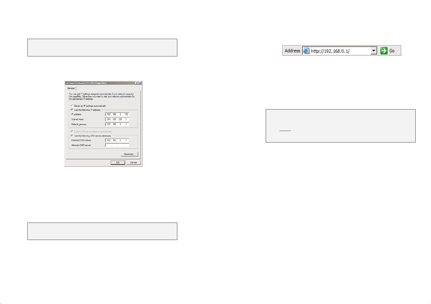
Select Use the following IP address and enter the following details:
IP address: 192.168.0.100
Subnet mask: 255.255.255.0
Default gateway: 192.168.0.1
Select Use the following DNS server addresses and enter:
Preferred DNS server: 192.168.0.1
Note: If you wish to retain your existing IP settings for this network
connection, click Advanced and Add the secondary IP address of
192.168.0.100, subnet mask 255.255.255.0.
The new password will take effect immediately, and you will be prompted
to enter it when completing the next step.
The Quick Setup Wizard will display.
5
6
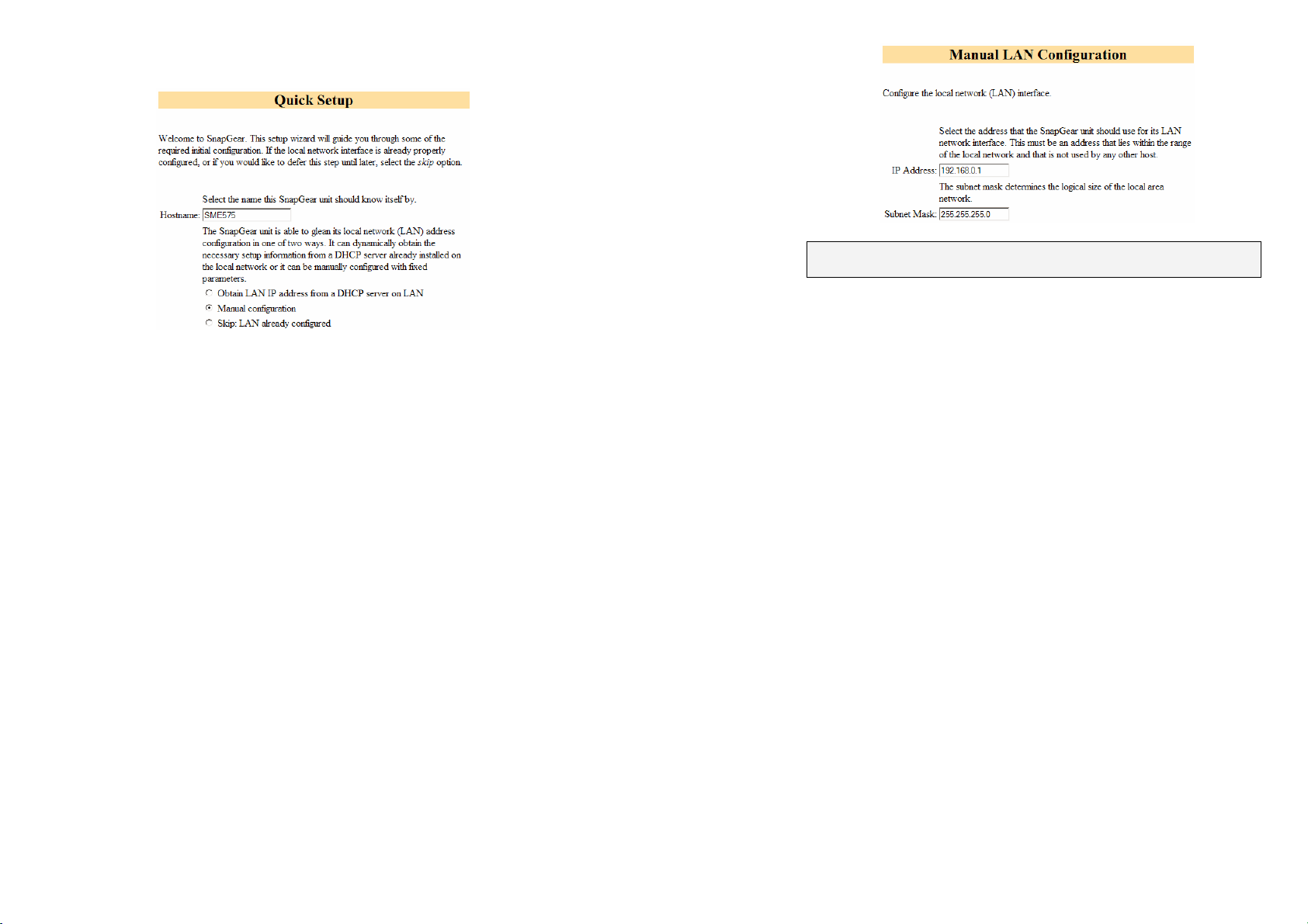
Hostname: You may change the name your CyberGuard SG appliance
knows itself by. This is not generally necessary.
Manual configuration: Select this to manually specify your CyberGuard
SG appliance’s LAN connection settings.
Skip: LAN already configured: Select this if you wish to use the
CyberGuard SG appliance’s initial network settings (IP address
192.168.0.1 and subnet mask 255.255.255.0) as a basis for your LAN
settings. You may skip to STEP 4.
Obtain LAN IP address from a DHCP server on LAN: It is
recommended that you statically configure your CyberGuard SG
appliance’s LAN connection settings rather than rely on an existing
DHCP server. However, you may select this if you have an existing
DHCP server that you wish to have automatically configure your
CyberGuard SG appliance’s LAN connection settings. You may skip to
STEP 4.
Note: This page will only display if you previously selected Manual
configuration. Otherwise skip to STEP 4.
Enter an IP address and Subnet mask for your CyberGuard SG
appliance’s LAN connection. You may choose to use the CyberGuard
SG appliance’s initial network settings if you are sure no other PC or
network device already has the address of 192.168.0.1.
The IP address will later be used as the gateway address for the PCs
on your LAN. To gain access through this gateway, the PCs on your
LAN must have an IP address within the bounds of the subnet described
by the CyberGuard SG appliance’s IP address and subnet mask (e.g.
using the CyberGuard SG appliance’s initial network settings,
192.168.0.2 – 192.168.0.254).
Take note of this IP address and subnet mask, as you will need them
later on.
Click Next.
Click Next.
7
8
STEP 4 Set up the CyberGuard SG appliance’s Internet
connection settings
First, attach your CyberGuard SG appliance to your modem device or
Internet connection medium. If necessary, give the modem device some
time to power up.
STEP 5 Set up the PCs on your LAN to access the
Internet
If you haven’t already, connect your CyberGuard SG appliance’s LAN
port directly to your LAN hub using the straight through Ethernet cable
(blue).
Note: if you are setting up the SG565, you may also connect PCs
directly to its LAN switch.
To access the Internet, the PCs on your LAN must all be set up to use
the CyberGuard SG appliance as their default gateway. This can be
done a number of different ways depending on how your LAN is set up.
If your LAN has a DHCP server already, proceed to STEP 5A.
If your LAN does not
If you are not sure, you probably want STEP 5B.
have a DHCP server, proceed to STEP 5B.
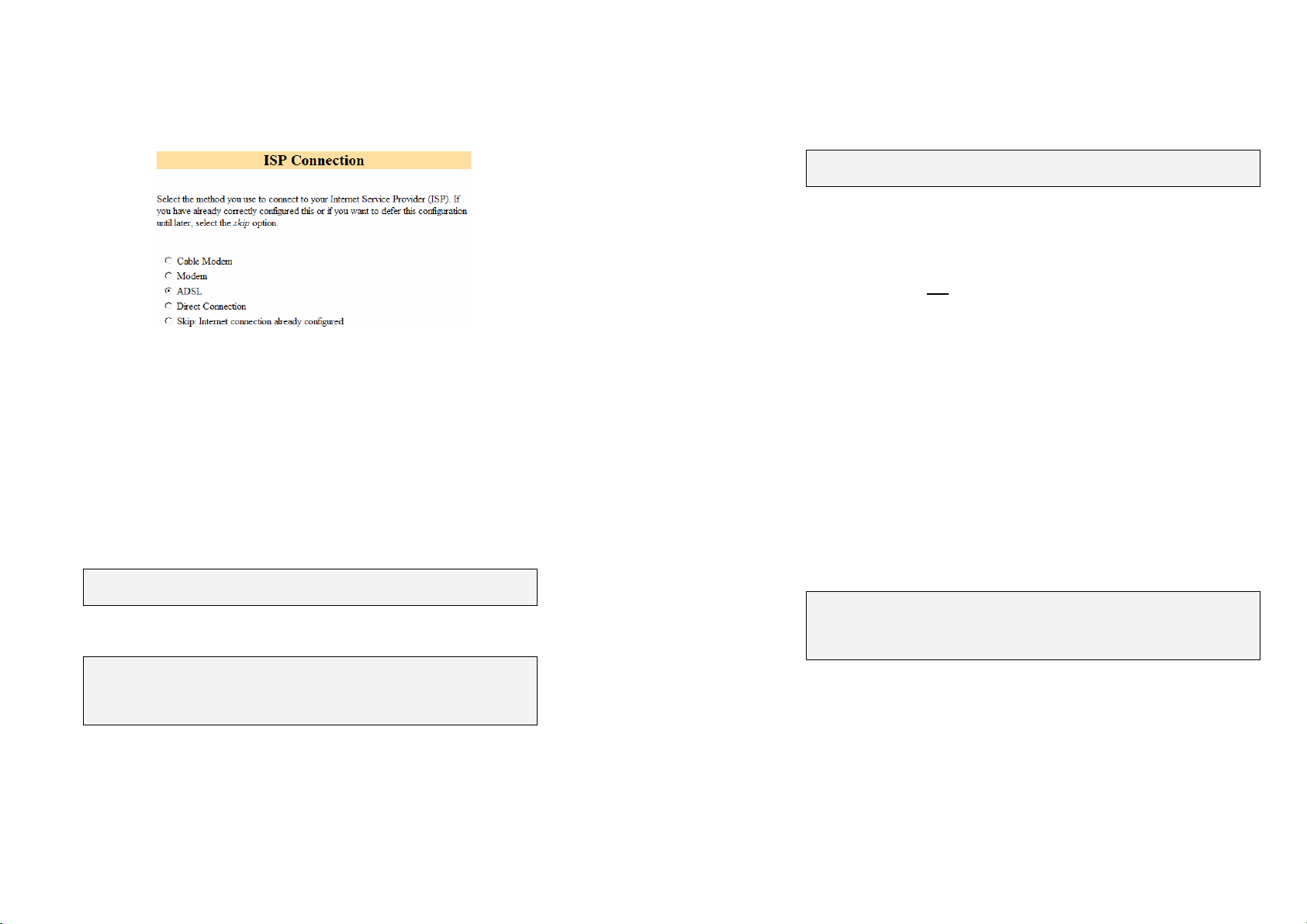
Select your Internet connection type and click Next.
If connecting using a cable modem, select the appropriate ISP. Choose
Generic cable modem provider if unsure.
If connecting using a regular analog modem, enter the details provided
by your ISP.
If connecting using an ADSL modem, select Auto detect ADSL
connection type and enter the details provided by your ISP. If auto
detection fails and you are unsure of your ADSL connection type,
contact your ISP.
If you have a direct connection to the Internet (e.g. a leased line), enter
the IP settings provided by your ISP.
Note: For detailed help for each of these options, please refer to the
User Manual.
Once the CyberGuard SG appliance’s Internet connection has been set
up, click Next, select Reboot and click Next again.
Note: If you changed the CyberGuard SG appliance’s LAN connection
settings in STEP 3, it may become uncontactable at this point. The next
step describes how to set up the PCs on your network to access the
CyberGuard SG appliance and the Internet.
STEP 5A LAN with a DHCP server
Add a lease to your existing DHCP server to reserve an IP address for
the CyberGuard SG appliance’s LAN connection.
If you chose to set the CyberGuard SG appliance’s LAN connection
settings using Manual configuration, you may simply remove this
address from the pool of available addresses.
Enter this same IP address as the gateway IP address to be handed out
by the DHCP server.
Enter this same IP address as the DNS server IP address to be handed
out by the DHCP server.
Restart all the PCs on the network (this will reset their gateway and DNS
addresses).
Note: The purpose of restarting the PCs is to force them to gain a new
DHCP lease. Alternatively you can use a utility such as ipconfig to
release then renew a lease, or disable and re-enable the network
connection.
9
10

STEP 5B LAN with no DHCP server
A DHCP server allows PCs to automatically obtain network settings
when they start up. If your network does not have a DHCP server, you
may either manually set up each PC on your network, or set up the
CyberGuard SG appliance's DHCP server.
Note: If you only have several PCs, we suggest manually setting up
your network. If you have more PCs, enabling the CyberGuard SG
appliance’s DHCP server is more scalable.
To manually set up each Windows PC on your network:
Click Start -> (Settings ->) Control Panel and double click Network
Connections (or in 95/98/Me, double click Network).
If presented with multiple connections, right click on Local Area
Connection (or appropriate network connection) and select Properties.
Select Internet Protocol (TCP/IP) and click Properties (or in 95/98/Me,
TCP/IP -> [your network card name] if there are multiple entries).
Enter the following details:
IP address is an IP address that is part of the same subnet range
as the CyberGuard SG appliance’s LAN connection (e.g. if using
the default settings, 192.168.0.2 – 192.168.0.254).
Subnet mask is the subnet mask of the CyberGuard SG
appliance’s LAN connection.
Default gateway is the IP address of the CyberGuard SG
appliance’s LAN connection.
Preferred DNS server is the IP address of the CyberGuard SG
appliance’s LAN connection.
Click OK (or in 95/98/Me, Add then OK, reboot the PC if prompted to do
so).
Perform these steps for each PC on your network.
Alternatively, to activate your CyberGuard SG appliance's DHCP server:
Launch Internet Explorer (or your preferred web browser) and navigate
to the IP address of the CyberGuard SG appliance’s LAN connection.
Note: If you changed your CyberGuard SG appliance’s LAN connection
settings from its default settings in STEP 3, it may be uncontactable at
this point. If so, manually set up a single PC as described at the
beginning of STEP 5B before continuing.
The Web Management Console will display.
Select DHCP Server from the Networking menu.
Click Add Server and configure the DHCP server with the following
details:
Gateway Address is the IP address of the CyberGuard SG
appliance’s LAN connection, or leave it blank.
DNS Address is the IP address of the CyberGuard SG
appliance’s LAN connection, or leave it blank.
WINS Address (optional) is the IP address of any existing WINS
server on your LAN.
Default Lease Time and Maximum Lease Time should generally
be left at their default values.
Initial Dynamic IP Address Range is a range of free IP
addresses on your LAN’s subnet for the CyberGuard SG
appliance to hand out to PCs on your LAN.
Note: For a detailed description of configuring DHCP Server Settings,
please refer to the User Manual.
Each PC on your LAN must now be set up to use DHCP. For each PC
on your LAN:
Click Start -> (Settings ->) Control Panel and double click Network
Connections (or in 95/98/Me, double click Network).
You are now finished.
11
If presented with multiple connections, right click on Local Area
Connection (or appropriate network connection) and select Properties.
12

Select Internet Protocol (TCP/IP) and click Properties (or in 95/98/Me,
TCP/IP -> [your network card name] if there are multiple entries) and
click Properties (in 95/98/Me, you may also have to click the IP Address
tab).
Check Obtain an IP address automatically, check Obtain DNS server
address automatically and click OK (in 95/98/Me, reboot the PC if
prompted to do so).
You are now finished.
Common VPN Scenarios
Generally there are two common scenarios in which you will want to set
up your CyberGuard SG appliance(s):
• LAN-to-LAN: Linking two branch offices across the Internet. For this
case we recommend using IPSec. The VPN connection can operate
with both static and dynamic public (Internet) IP addresses.
For the example below we assume that CyberGuard SG appliances are
installed at either end, and that both have a static public IP address, or
one is static and one is dynamic. The example tunnel will be using preshared keys for authentication, aggressive mode for keying, and be
established going out through the default gateway interface. Proceed to
CyberGuard SG to CyberGuard SG VPN (IPSec).
Please refer to the IPSec section of the User Manual if you are
trying to set up something more complex, and for a detailed
description of all available options.
• Roaming: Connecting to your CyberGuard SG appliance, installed at
your home or office, from a single PC at a remote location. For this
case we recommend using PPTP because the client is standard in
Windows and other operating systems, and it is quite simple to set up.
Proceed to Remote Workstation to CyberGuard SG VPN (PPTP).
CyberGuard SG to CyberGuard SG VPN (IPSec)
Perform these steps for either end of the connection. Unless instructed
otherwise, leave all options at their default settings.
STEP 1 Enable IPSec
Select IPSec from the VPN menu.
Underneath IPSec General Settings select This end has a static IP
address IPSec endpoint, or This end has a dynamic IP address
IPSec endpoint as appropriate. This is referring to the public (Internet)
IP address of this CyberGuard SG appliance. Check with your ISP if
unsure.
Check Enable IPSec, and click Apply.
13
14

STEP 2 Add a New IPSec Connection
Select the Add New Tunnel tab at the top of the window.
Enter a descriptive name for the connection in Tunnel name.
Select This tunnel will be using Aggressive mode Automatic Keying
(IKE).
Select The remote party has a static IP address or The remote party
has a dynamic IP address as appropriate. This is referring to the
public (Internet) IP address of the other CyberGuard SG appliance.
Check with your ISP if unsure.
Click Continue.
STEP 3 Local Endpoint Settings
If you selected This end has a dynamic IP address IPSec endpoint,
enter snap@branch as the Required Endpoint ID.
Click Continue.
STEP 4 Remote Endpoint Settings
If you selected The remote party has a static IP address, enter the
other CyberGuard SG appliance's public (Internet) IP address in The
remote party's IP address.
If you selected The remote party has a dynamic IP address, enter
snap@branch as the Required Endpoint ID.
Note: Please note again that this example is not suitable for setting up a
connection where both ends have dynamic IP address, for this scenario
please refer to the IPSec section of the User Manual.
Click Continue.
STEP 5 Phase 1 Settings
You must choose a Preshared Secret to authenticate the connection.
This passphrase can be any character string you like (recommended at
least 24 characters), it may contain spaces, and must be entered
identically on both CyberGuard SG appliances.
Note: It is important that you keep this information secret, much like a
password. The preshared secret is fundamental to IPSec encryption.
Click Continue.
15
16

STEP 6a Phase 2 Settings
Remote Workstation to CyberGuard SG VPN (PPTP)
STEP 1 Enable PPTP Server
Select PPTP VPN Server from the Networking menu. The table below
describes the fields in the PPTP VPN Server Setup page and the
options in enabling and configuring VPN access.
Enter the network address and network mask for the Local Network
(this CyberGuard SG appliance) and the Remote Network (the other
CyberGuard SG appliance). You can check this by opening
Diagnostics in a new browser window and looking under LAN
Interface, e.g. if the IP Address is 192.168.1.1 and Netmask is
255.255.255.0, enter 192.168.1.0/255.255.255.0.
Note: The two LANs being connected by the IPSec connection must
have network addresses that are different to each other, e.g.
192.168.1.0/255.255.255.0 and 192.168.2.0/255.255.255.0.
Click Apply and you're done.
STEP 6b Repeat
Your CyberGuard SG appliance is now activated for IPSec VPN. Once
you have completed the steps at each end you will be up and running.
STEP 7 Verify
Under Tunnel List in the General Settings tab, check Status to see
whether the connection is Down or Running. Status will display
Negotiating Phase 1 then Negotiating Phase 2 as the connection is
being established.
Enable PPTP
IP Address(es) to
Assign VPN Clients
Authentication
Scheme
Authentication
Database
Check this box to enable the establishment of
PPTP connections to your CyberGuard SG
appliance.
Enter a range of free IP addresses on your
LAN to assign to the remote connections.
MSCHAPv2 is the most secure and
recommended. It uses encrypted passwords.
CHAP is less secure, and similarly PAP is
even less secure, but more common. In some
cases you may have to choose them if the
default does not work.
Leave this as Local unless you wish to use
another server to authenticate PPTP VPN
clients. Refer to the User Manual if this is the
case.
17
18

STEP 2 Add User Account(s)
Once you have set up the VPN server, select Continue.
Before remote users can set up a VPN tunnel to the CyberGuard SG
appliance’s PPTP server, they must have user accounts set up. The
field options in the Add New Account are detailed below.
As new VPN user accounts are added, they are displayed on the
updated Account List.
To modify the password of an existing account, Select the account in the
Account List then enter New Password and Confirm in the Delete or
Change Password for the Selected Account field.
Similarly to delete an existing account, Select the account in the
Account List then check Delete in the Delete or Change Password for
the Selected Account field.
If you request a change to a User Account and it is successful, the PPTP
VPN Server Setup page will be displayed with the change noted. If the
change was unsuccessful, an error will be reported.
STEP 3 Configure Remote Client
At the remote sites there is generally no need for any special client
software. Your CyberGuard SG appliance’s PPTP server supports the
standard PPTP client software included with Windows. The virtual
private network connection is simple to configure using the standard
Dial-Up Networking software. PPTP is also compatible with Linux/Unix
PPTP client software.
These instructions will cover a Windows 2000 client. Please refer to the
User Manual if you have a different operating system.
Click Start, Settings, Network and Dialup Connections. Choose
Make New Connection
.
Username
Windows
Domain
Password
Confirm
This User Name is required for VPN authentication
only. The name selected is case sensitive (for example
Jimsmith is not the same as jimsmith).
Optional. Most Windows clients expect you to specify a
domain name in upper case.
Enter the password for the remote VPN user.
Re-enter the password to confirm.
19
Choose Connect to a private network through the Internet. Click
Next.
20

Enter the CyberGuard SG appliance’s public (Internet) IP address in the
Destination Address and click Next. Select the Connection
Availability that you require on the next window and click Next, which
will display the final window in this wizard.
Choose a name for your new VPN connection, e.g. My Office VPN.
Your client machine should be connected to the Internet in the normal
way (dialout, ADSL, cable modem etc.).
Enter the Username and Password set up earlier and click the
Connect button.
After you have been authenticated to the network, you can check your email, use the office printer, access shared files and browse the network –
as if you were physically connected to the LAN.
To disconnect the VPN tunnel connection to the remote CyberGuard SG
appliance double click on the Dial-Up Networking icon in the Windows
task bar and close the connection.
STEP 4 Verify
Your VPN connection is easily verified by attempting a connection as
above. Once the connection has succeeded your client’s Windows task
bar will contain a Dial-Up Networking icon and will flash to indicate
activity. You may also double click this icon to see further statistics.
Terms and Conditions SnapGear Warranty
Standard Warranty
SnapGear, Inc., its parent, affiliates and subsidiaries, (collectively, "SnapGear")
warrant your SnapGear product to be in good working order and to be free from
defects in workmanship and material (except in those cases where the
materials are supplied by the Purchaser) under normal and proper use and
service for the period of one (1) year from the date of original purchase from an
Authorized SnapGear reseller. In the event that this product fails to meet this
warranty within the applicable warranty period, and provided that SnapGear
confirms the specified defects, Purchaser's sole remedy is to have SnapGear, in
SnapGear's sole discretion, repair or replace such product at the place of
manufacture, at no additional charge other than the cost of freight of the
defective product to and from the Purchaser. Repair parts and replacement
products will be provided on an exchange basis and will be either new or
reconditioned. SnapGear will retain, as its property, all replaced parts and
products. Notwithstanding the foregoing, this hardware warranty does not
include service to replace or repair damage to the product resulting from
accident, disaster, abuse, misuse, electrical stress, negligence, any nonSnapGear modification of the product except as provided or explicitly
recommended by SnapGear, or other cause not arising out of defects in
material or workmanship. This hardware warranty also does not include service
to replace or repair damage to the product if the serial number or seal or any
part thereof has been altered, defaced or removed. If SnapGear does not find
the product to be defective, the Purchaser will be invoiced for said inspection
and testing at SnapGear's then current rates, regardless of whether the product
is under warranty.
21
22

Limitation of Liability
No action, regardless of form, arising from this warranty may be brought by
either party more than two (2) years after the cause of action has occurred.
Purchaser expressly agrees that SnapGear's liability, if any, shall be limited
solely to the replacement or repair of the product in accordance with the
warranties specifically and expressly set forth herein. The remedies of the
Purchaser are the exclusive and sole remedies available, and, in the event of a
breach or repudiation of any provision of this agreement by SnapGear, the
Purchaser shall not be entitled to receive any incidental damages as that term is
defined in Section 2-715 of the Uniform Commercial Code. SnapGear waives
the benefit of any rule that disclaimer of warranty shall be construed against
SnapGear and agrees that such disclaimers herein shall be construed liberally
in favor of SnapGear. THE
EXCLUSIVE WARRANTIES GIVEN IN CONNECTION WITH THE PRODUCT
AND THE HARDWARE. SNAPGEAR DISCLAIMS ALL OTHER WARRANTIES,
EXPRESS OR IMPLIED, INCLUDING WITHOUT LIMITATION, ANY
WARRANTIES AS TO THE SUITABILITY OR MERCHANTABILITY OR
FITNESS FOR ANY PARTICULAR PURPOSE AND NONINFRINGEMENT OF
THIRD PARTY RIGHTS. SNAPGEAR DOES NOT PROMISE THAT THE
PRODUCT IS ERROR-FREE OR WILL OPERATE WITHOUT INTERRUPTION.
IN NO EVENT SHALL SNAPGEAR BE LIABLE FOR ANY LOST OR
ANTICIPATED PROFITS, OR ANY INCIDENTAL, EXEMPLARY, SPECIAL OR
CONSEQUENTIAL DAMAGES, REGARDLESS OF WHETHER SNAPGEAR
WAS ADVISED OF THE POSSIBILITY OF SUCH DAMAGES.
FOREGOING WARRANTIES ARE THE SOLE AND
Extended Four Year Warranty
If Purchaser buys Extended Warranty at time of purchase of the product
or within thirty (30) days from date of original purchase, the period of
warranty will be extended by three (3) additional years to a total of four
(4) years.
Return Procedure
If this product requires service during the applicable warranty period, a
Return Materials Authorization (RMA) number must first be obtained
from SnapGear. Product that is returned to SnapGear for service or
repair without an RMA number will be returned to the sender
unexamined. Product should be returned, freight prepaid, in its original
or equivalent packaging, to an authorized SnapGear Service Center.
Proof of purchase date must accompany the returned product and the
Purchaser shall agree to insure the product or assume the risk of loss of
damage in transit. Contact SnapGear for further information.
Technical Support
Purchaser is entitled to thirty (30) days free telephone support (USA
ONLY) and thirty (30) days free e-mail support (world wide) from date of
purchase provided that the Purchaser first register their product(s) with
SnapGear either via filling in and posting or faxing the form found in the
Quick Install Guide, or filling in the on-line form
http://www.snapgear.com/registration.html. Telephone and e-mail
support is available from 9:00 AM to 5:00 PM, Mountain Time.
SnapGear's standard warranty includes free access to SnapGear's
Knowledge Base as well as any application notes, white papers and
other on-line resources that may become available from time to time.
SnapGear reserves the right to discontinue all support for products that
are no longer covered by warranty.
23
24

SNAPGEAR END USER LICENSE AGREEMENT
IMPORTANT
READ BEFORE USING THE ACCOMPANYING SOFTWARE
YOU SHOULD CAREFULLY READ THE FOLLOWING TERMS AND CONDITIONS BEFORE
USING THE ACCOMPANYING SOFTWARE, THE USE OF WHICH IS LICENSED FOR USE
ONLY AS SET FORTH BELOW. IF YOU DO NOT AGREE TO THE TERMS AND CONDITIONS
OF THIS AGREEMENT, DO NOT USE THE SOFTWARE. IF YOU USE ANY PART OF THE
SOFTWARE, SUCH USE WILL INDICATE THAT YOU ACCEPT THESE TERMS.
You have acquired a product that includes SnapGear (“SnapGear”) proprietary software and/or
proprietary software licensed to SnapGear. This SnapGear End User License Agreement
(“EULA”) is a legal agreement between you (either an individual or a single entity) and SnapGear
for the installed software product of SnapGear origin, as well as associated media, printed
materials, and “online” or electronic documentation (“Software”). By installing, copying,
downloading, accessing, or otherwise using the Software, you agree to be bound by the terms of
this EULA. If you do not agree to the terms of this EULA, SnapGear is not willing to license the
Software to you. In such event, do not use or install the Software. If you have purchased the
Software, promptly return the Software and all accompanying materials with proof of purchase for
a refund.
Products with separate end user license agreements that may be provided along with the
Software are licensed to you under the terms of those separate end user license agreements.
LICENSE GRANT. Subject to the terms and conditions of this EULA, SnapGear grants you a
nonexclusive right and license to install and use the Software on a single CPU, provided that, (1)
you may not rent, lease, sell, sublicense or lend the Software; (2) you may not reverse engineer,
decompile, disassemble or modify the Software, except and only to the extent that such activity is
expressly permitted by applicable law notwithstanding this limitation; and (3) you may not transfer
rights under this EULA unless such transfer is part of a permanent sale or transfer of the Product,
you transfer at the same time all copies of the Software to the same party or destroy such
materials not transferred, and the recipient agrees to this EULA.
No license is granted in any of the Software’s proprietary source code. This license does not
grant you any rights to patents, copyright, trade secrets, trademarks or any other rights with
respect to the Software.
You may make a reasonable number of copies of the electronic documentation accompanying
the Software for each Software license you acquire, provided that, you must reproduce and
include all copyright notices and any other proprietary rights notices appearing on the electronic
documentation.
SnapGear reserves all rights not expressly granted herein.
INTELLECTUAL PROPERTY RIGHTS. The Software is protected by copyright laws,
international copyright treaties, and other intellectual property laws and treaties. SnapGear and
its suppliers retain all ownership of, and intellectual property rights in (including copyright), the
Software components and all copies thereof, provided however, that certain components of the
Software are components licensed under the GNU General Public License (version 2), which
SnapGear supports. You may obtain a copy of the GNU General Public License at
http:/www.fsf.org/copyleft/gpl.html
. SnapGear will provide source code for any of the components
of the Software licensed under the GNU General Public License upon request.
EXPORT RESTRICTIONS. You agree that you will not export or re-export the Software, any part
thereof, or any process or service that is the direct product of the Software in violation of any
applicable laws or regulations of the United States or the country in which you obtained them.
U.S. GOVERNMENT RESTRICTED RIGHTS. The Software and related documentation are
provided with Restricted Rights. Use, duplication, or disclosure by the Government is subject to
restrictions set forth in subparagraph (c) (1) (ii) of the Rights in Technical Data and Computer
Software clause at DFARS 252.227-7013 or subparagraphs (c) (1) and (2) of the Commercial
Computer Software – Restricted Rights at 48 C.F.R. 52.227-19, as applicable, or any successor
regulations.
TERM AND TERMINATION. This EULA is effective until terminated. The EULA terminates
immediately if you fail to comply with any term or condition. In such an event, you must destroy
all copies of the Software. You may also terminate this EULA at any time by destroying the
Software.
GOVERNING LAW AND ATTORNEY’S FEES. This EULA is governed by the laws of the State
of Utah, USA, excluding its conflict of law rules. You agree that the United Nations Convention
on Contracts for the International Sale of Goods is hereby excluded in its entirety and does not
apply to this EULA. If you acquired this Software in a country outside of the United States, that
country’s laws may apply. In any action or suit to enforce any right or remedy under this EULA or
to interpret any provision of this EULA, the prevailing party will be entitled to recover its costs,
including reasonable attorneys’ fees.
ENTIRE AGREEMENT. This EULA constitutes the entire agreement between you and
SnapGear with respect to the Software, and supersedes all other agreements or representations,
whether written or oral. The terms of this EULA can only be modified by express written consent
of both parties. If any part of this EULA is held to be unenforceable as written, it will be enforced
to the maximum extent allowed by applicable law, and will not affect the enforceability of any
other part.
Should you have any questions concerning this EULA, or if you desire to contact SnapGear for
any reason, please contact the SnapGear representative serving your company.
25
26

THE FOLLOWING DISCLAIMER OF WARRANTY AND LIMITATION OF LIABILITY IS
INCORPORATED INTO THIS EULA BY REFERENCE.
NOT FAULT TOLERANT. THE SOFTWARE IS NOT FAULT TOLERANT. YOU HAVE
INDEPENDENTLY DETERMINED HOW TO USE THE SOFTWARE IN THE DEVICE, AND
SNAPGEAR HAS RELIED UPON YOU TO CONDUCT SUFFICIENT TESTING TO DETERMINE
THAT THE SOFTWARE IS SUITABLE FOR SUCH USE.
LIMITED WARRANTY. SnapGear warrants the media containing the Software for a period of
ninety (90) days from the date of original purchase from SnapGear or its authorized retailer.
Proof of date of purchase will be required. Any updates to the Software provided by SnapGear
(which may be provided by SnapGear at its sole discretion) shall be governed by the terms of this
EULA. In the event the product fails to perform as warranted, SnapGear’s sole obligation shall
be, at SnapGear’s discretion, to refund the purchase price paid by you for the Software on the
defective media, or to replace the Software on new media. SnapGear makes no warranty or
representation that its Software will meet your requirements, will work in combination with any
hardware or application software products provided by third parties, that the operation of the
software products will be uninterrupted or error free, or that all defects in the Software will be
corrected.
SNAPGEAR DISCLAIMS ANY AND ALL OTHER WARRANTIES, WHETHER EXPRESS OR
IMPLIED, INCLUDING WITHOUT LIMITATION, ANY IMPLIED WARRANTIES OF
MERCHANTABILITY OR FITNESS FOR A PARTICULAR PURPOSE. OTHER THAN AS
STATED HEREIN, THE ENTIRE RISK AS TO SATISFACTORY QUALITY, PERFORMANCE,
ACCURACY, AND EFFORT IS WITH YOU. ALSO, THERE IS NO WARRANTY AGAINST
INTERFERENCE WITH YOUR ENJOYMENT OF THE SOFTWARE OR AGAINST
INFRINGEMENT. IF YOU HAVE RECEIVED ANY WARRANTIES REGARDING THE DEVICE
OR THE SOFTWARE, THOSE WARRANTIES DO NOT ORIGINATE FROM, AND ARE NOT
BINDING ON, SNAPGEAR.
NO LIABILITY FOR CERTAIN DAMAGES. EXCEPT AS PROHIBITED BY LAW, SNAPGEAR
SHALL HAVE NO LIABILITY FOR COSTS, LOSS, DAMAGES OR LOST OPPORTUNITY OF
ANY TYPE WHATSOEVER, INCLUDING BUT NOT LIMITED TO, LOST OR ANTICIPATED
PROFITS, LOSS OF USE, LOSS OF DATA, OR ANY INCIDENTAL, EXEMPLARY SPECIAL OR
CONSEQUENTIAL DAMAGES, WHETHER UNDER CONTRACT, TORT, WARRANTY OR
OTHERWISE ARISING FROM OR IN CONNECTION WITH THIS EULA OR THE USE OR
PERFORMANCE OF THE SOFTWARE. IN NO EVENT SHALL SNAPGEAR BE LIABLE FOR
ANY AMOUNT IN EXCESS OF THE LICENSE FEE PAID TO SNAPGEAR UNDER THIS EULA.
SOME STATES AND COUNTRIES DO NOT ALLOW THE LIMITATION OR EXCLUSION OF
LIABILITY FOR INCIDENTAL OR CONSEQUENTIAL DAMAGES, SO THIS LIMITATION MAY
NOT APPLY TO YOU.
Contact Details
USA Australia
7984 South Welby Park Drive
Suite #101
West Jordan, UT 84088
USA
Phone +1 801 282 8492
Fax +1 801 282 8496
825 Stanley St
Woolloongabba QLD 4102
Australia
Phone +61 7 3435 2888
Fax +61 7 3891 3630
Product Registration
For prompt product registration please go to the CyberGuard website at:
http://www.cyberguard.com/snapgear/registration.html
You will require a current email address to register your product.
27
28
Part Number: 520093-00 February 7th, 2005

Product
Compliance
Information
520055-07-SPC 1

Contents of Kits
Part Descriptions Quantities
Products SG300
(was LITE300)
990126
Telephone extension cable,
SG630
(was PCI630)
990071
SG635
(was PCI635)
990135
6ft (1.8m)
Ethernet cross-over cable,
1 1 1 1 1 1
6ft (1.8m) grey
Ethernet cross-over cable,
6ft (1.8m) red
Ethernet patch cable, 6ft
2 1 1 1 1 1 1
(1.8m) blue
5VDC switching power
1 1 1 1
supply unit
6VDC switching power
supply unit
6VDC wall mount plug
pack
12VDC wall mount plug
1
pack
SG530
(was SME530)
990064
SG550
(was SME550)
990065
SG570
(was SME570)
990107
SG575
(was SME575)
990108
SG710
990136
SG710+
990183
IEC mains power supply
1 1 1 1 1 1
cable
Quick Installation Guide 1 1 1 1 1 1 1 1 1
CDrom 1 1 1 1 1 1 1 1 1
520055-07-SPC 2

Relevant Certifications
Compliance Certifications Relevant to
Products SG300
(was LITE300)
990126
SG630
(was PCI630)
990071
SG635
(was PCI635)
990135
SG530
(was SME530)
990064
SG550
(was SME550)
990065
SG570
(was SME570)
990107
SG575
(was SME575)
990108
SG710
990136
SG710+
990183
FCC Class A
FCC Class B
CE
C-Tick
TUV
Industry Canada
• • • • • • • • •
• • • • • • • • •
• • • • • • • • •
•
• •
• • • • • • • • •
520055-07-SPC 3

Hereby, CyberGuard Corporation., declares that this ITE is in compliance with the essential requirements and other relevant provisions
of Directive 1999/5/EC.
CyberGuard Corporation. vakuuttaa täten että ITE tyyppinen laite on direktiivin 1999/5/EY oleellisten vaatimusten ja sitä koskevien
direktiivin muiden ehtojen mukainen.
Hierbij verklaart CyberGuard Corporation. dat het toestel ITE in overeenstemming is met de essentiële eisen en de andere relevante
bepalingen van richtlijn 1999/5/EG
Bij deze verklaart CyberGuard Corporation. dat deze ITE voldoet aan de essentiële eisen en aan de overige relevante bepalingen van
Richtlijn 1999/5/EC.
Par la présente CyberGuard Corporation. déclare que l'appareil ITE est conforme aux exigences essentielles et aux autres dispositions
pertinentes de la directive 1999/5/CE
Par la présente, [nom du constructeur] déclare que ce [type d'équipement] est conforme aux exigences essentielles et aux autres
dispositions de la directive 1999/5/CE qui lui sont applicables
Härmed intygar CyberGuard Corporation. att denna ITE står I överensstämmelse med de väsentliga egenskapskrav och övriga
relevanta bestämmelser som framgår av direktiv 1999/5/EG.
Undertegnede CyberGuard Corporation. erklærer herved, at følgende udstyr ITE overholder de væsentlige krav og øvrige relevante
krav i direktiv 1999/5/EF
Hiermit erklärt CyberGuard Corporation., dass sich dieser/diese/dieses ITE in Übereinstimmung mit den grundlegenden Anforderungen
und den anderen relevanten Vorschriften der Richtlinie 1999/5/EG befindet". (BMWi)
Hiermit erklärt CyberGuard Corporation. die Übereinstimmung des Gerätes ITE mit den grundlegenden Anforderungen und den
anderen relevanten Festlegungen der Richtlinie 1999/5/EG. (Wien)
ΜΕ ΤΗΝ ΠΑΡΟΥΣΑ CyberGuard Corporation. ∆ΗΛΩΝΕΙ ΟΤΙ ITE ΣΥΜΜΟΡΦΩΝΕΤΑΙ ΠΡΟΣ ΤΙΣ ΟΥΣΙΩ∆ΕΙΣ ΑΠΑΙΤΗΣΕΙΣ ΚΑΙ ΤΙΣ
ΛΟΙΠΕΣ ΣΧΕΤΙΚΕΣ ∆ΙΑΤΑΞΕΙΣ ΤΗΣ Ο∆ΗΓΙΑΣ 1999/5/ΕΚ
Con la presente CyberGuard Corporation. dichiara che questo ITE è conforme ai requisiti essenziali ed alle altre disposizioni pertinenti
stabilite dalla direttiva 1999/5/CE.
Por medio de la presente CyberGuard Corporation. declara que el ITE cumple con los requisitos esenciales y cualesquiera otras
disposiciones aplicables o exigibles de la Directiva 1999/5/CE
CyberGuard Corporation. declara que este ITE está conforme com os requisitos essenciais e outras disposições da Directiva
1999/5/CE.
520055-07-SPC 4

Compliance Information
EMC, Safety and R&TTE Directive Compliance
The CE mark, if applicable, is affixed to this product to confirm compliance with the following European Community Directives:
o Council Directive 89/336/EEC of 3 May 1989 on the approximation of the laws of Member States relating to electromagnetic
compatibility; and
o Council Directive 73/23/EEC of 19 February 1973 on the harmonization of the laws of Member States relating to electrical
equipment designed for use within certain voltage limits; and
o Council Directive 1999/5/EC of 9 March on radio equipment and telecommunications terminal equipment and the mutual
recognition of their conformity.
FCC Part 15 Regulations
This equipment has been tested and found to comply with the limits for a Class B digital device, pursuant to Part 15 of the FCC rules.
These limits are designed to provide reasonable protection against harmful interference in a residential installation. This equipment
generates, uses, and can radiate radio frequency energy, and if not installed and used in accordance with the instructions, may cause
harmful interference to radio communications. However, there is no guarantee that interference will not occur in a particular installation.
If this equipment does cause harmful interference to radio or television reception, which can be determined by turning the equipment off
and on, the user is encouraged to try to correct the interference by one or more of the following measures:
This device complies with Part 15 of the FCC rules. Operation of this device is subject to the following conditions: (1) This device may
not cause harmful interference, and (2) this device must accept any interference that may cause undesired operation.
WARNING – Changes or modifications to this unit not expressly approved by the party responsible for compliance could void the user’s
authority to operate the equipment.
o Reorient or relocate the receiving antenna.
o Increase the separation between the equipment and receiver.
o Plug the equipment into an outlet on a circuit different from that to which the receiver is connected.
o Consult the dealer or an experienced radio/TV technician for help.
RF Exposure Statement
IMPORTANT NOTE: To comply with FCC RF exposure compliance requirements, the antenna used for this transmitter must be
installed to provide a separation distance of at least 20cm from all persons and must not be co-located or operating in conjunction with
any other antenna or transmitter.
Industry Canada
This Class B digital apparatus complies with Canadian ICES-003.
Cet appariel numérique de la classe B est conforme à la norme NMB-003 du Canada.
Operation is subject to the following two conditions:
¾ This device may not cause harmful interference, and
¾ This device must accept any interference, including interference that may cause undesired operation of the device.
Antenna Statements
This device has been designed to operate with an antenna having a maximum gain of 1.46dBi. Antenna having a higher gain is strictly
prohibited per regulations of Industry Canada. The required antenna impedance is 50 ohms.
To reduce potential radio interference to others, the antenna type and its gain should be so chosen that the equivalent isotropic radiated
power (EIRP) is not more than that required for successful communication.
RF Exposure Statement
The installer of this radio equipment must ensure that the antenna is located or pointed such that it does not emit RF fields in excess of
Health Canada limits for the general population; consult safety code 6, obtainable from Health Canada’s website www.hc-sc.gc.ca/rpb
.
520055-07-SPC 5

FCC Part 68 Regulations require that the following information be provided to the customer:
Product: MultiTech Systems modem module
Model: MT5634SMI
FCC Registration Number: AU7-USA-25814-M5-E
1. This equipment complies with Part 68 of the FCC rules. On the side or bottom of this equipment is a label that contains, among
other information, the FCC Registration Number and Ringer Equivalence Number (REN), if applicable, for this equipment. If
required, this information must be given to the telephone company.
2. An FCC-compliant telephone cord and modular plug is provided with this equipment. This equipment is designed to be connected
to the telephone network or premises wiring using a compatible modular jack that is Part 68-compliant. See installation instructions
for details.
3. If your telephone equipment causes harm to the telephone network, the telephone company may discontinue your service
temporarily. If possible they will notify you in advance. But if advance notice isn’t practical, you will be notified as soon as
possible. You will be advised of your right to file a complaint with the FCC.
4. Your telephone company may make changes in its facilities, equipment, operations or procedures that could affect the proper
operation of your equipment. If they do, you will be given advance notice to give you an opportunity to maintain an uninterrupted
service.
5. If you experience trouble with this equipment, please contact AT&T Global for repair/warranty information. The telephone company
may ask you to disconnect this equipment from the network until the problem has been corrected or until you are suer the
equipment id not malfunctioning.
6. This unit contains no user-serviceable parts.
7. The FCC recommends that the AC outlet to which equipment requiring AC power is provided with and AC surge arrestor.
8. The REN is ude to determine the quantity of devices which may connected to the telephone line. Excessive RENs on the
telephone line may result in the devices not ringing in response to an incomming call. In most, but not all areas, the sum of RENs
should not exceed five (5.0). To be certain of the number of devices that may be connected to a line, as determined by the total
RENs, contact the local telephone company.
9. The following information may be required when applying to your local telephone company for leased line facilities.
Canadian Equipment Limitations
NOTE: The Industry Canada Certification label identifies certified equipment. This certification means that the equipment meets certain
telecommunications network protective, operational and safety requirements. The Department of Commerce does not guarantee the
equipment will operate to the user’s satisfaction.
Before installing this equipment, users should ensure that it is permissible to be connected to the facilities of the local
telecommunications company. The equipment must also be installed using an acceptable method of connection. In some cases, the
company’s inside wiring associated with a single line individual service may be extended by means of a certified connector assembly
(telephone extension cord). The customer should be aware that compliance with the above conditions may not prevent degradation of
service in some situations.
Repairs to certified equipment should be made by an authorized Canadian maintenance facility designated by the supplier. Any repairs
or alterations made by the user to this equipment, or equipment malfunctions, may give the telecommunications company cause to
request the user to disconnect the equipment.
Users should ensure for their own protection that the electrical ground connections of the power utility, telephone lines and internal
metallic water pipe system, if present, are connected together. This precaution may be particularly important in rural areas.
WARNING – Users should not attempt to make such connections themselves, but should contact the appropriate electric inspection
authority, or an electrician, as appropriate.
The load number (LN) assigned to each terminal device denotes the percentage of the total load to be connected to a telephone loop
that is used by the device, to prevent overloading. The termination on a loop may consist of of any combination of devices subject only
to the equipment that the total of the LNs of all devices does not exceed 100.
The ringer equivalence number (REN) assigned to each terminal adaptor is used to determine the total number of devices that may be
connected to each circuit. The sum of the RENs from all devices in the circuit should not exceed a total of 5.0.
Service Type REN USOC
Analog 0.3B RJ-11C
520055-07-SPC 6

Declaration of Conformity
The products herewith comply with all applicable essential requirements of all applicable directives
Application of Low Voltage Directive (73/23/EEC)
Council Directive EMC Directive (89/336/EEC)
R & TTE Directive (1999/5/EC)
Applicable Standards EN55022: 1998; A1: 2000, A2: 2003
EN55024: 1998; A1: 2001, A2: 2003
EN61000-3-2: 2000
EN61000-3-3: 1995; A1: 2001
EN60950: 2000 (where applicable)
Manufacturer: CyberGuard Corporation
350 SW 12
Deerfield Beach
Florida 33442
USA
Phone: +1 954 375 3500
Fax: +1 954 375 3501
Type of Equipment: Information Technology Equipment
Equipment Description:
Part # Description
990126 KIT SG300
990071 KIT SG630
990135 KIT SG635 (was PCI635)
990064 KIT SG530
990065 KIT SG550 (was SME550)
990107 KIT SG570 (was SME570)
990108 KIT SG575
990136 KIT SG710
990183 KIT SG710+
I, the undersigned, hereby declare that the equipment specified above conforms to the above Directives and
Standards.
Mr. Rick Stevenson
......................... .......................................................
(NAME OF AUTHORIZED PERSON)
General Manager (SnapGear Division)
......................... .......................................................
(TITLE OF AUTHORIZED PERSON)
16 March 2005
.........................
(DATE OF ISSUE)
th
Avenue
(was LITE300)
(was PCI630)
(was SME530)
(was SME575)
520055-07-SPC 7
 Loading...