

Page 1
1
2
3
V3 Keypad Outdoor Intercom
VoIPon www.voipon.co.uk [email protected] Tel: +44 (0)1245 808195 Fax: +44 (0)1245 808299
The IP Endpoint Company
Quick Start Guide
1.0 Out-of-Box and Prior to Final Installation
1.1. Verify that you have received all of the parts listed on the Installation Quick
Reference placemat.
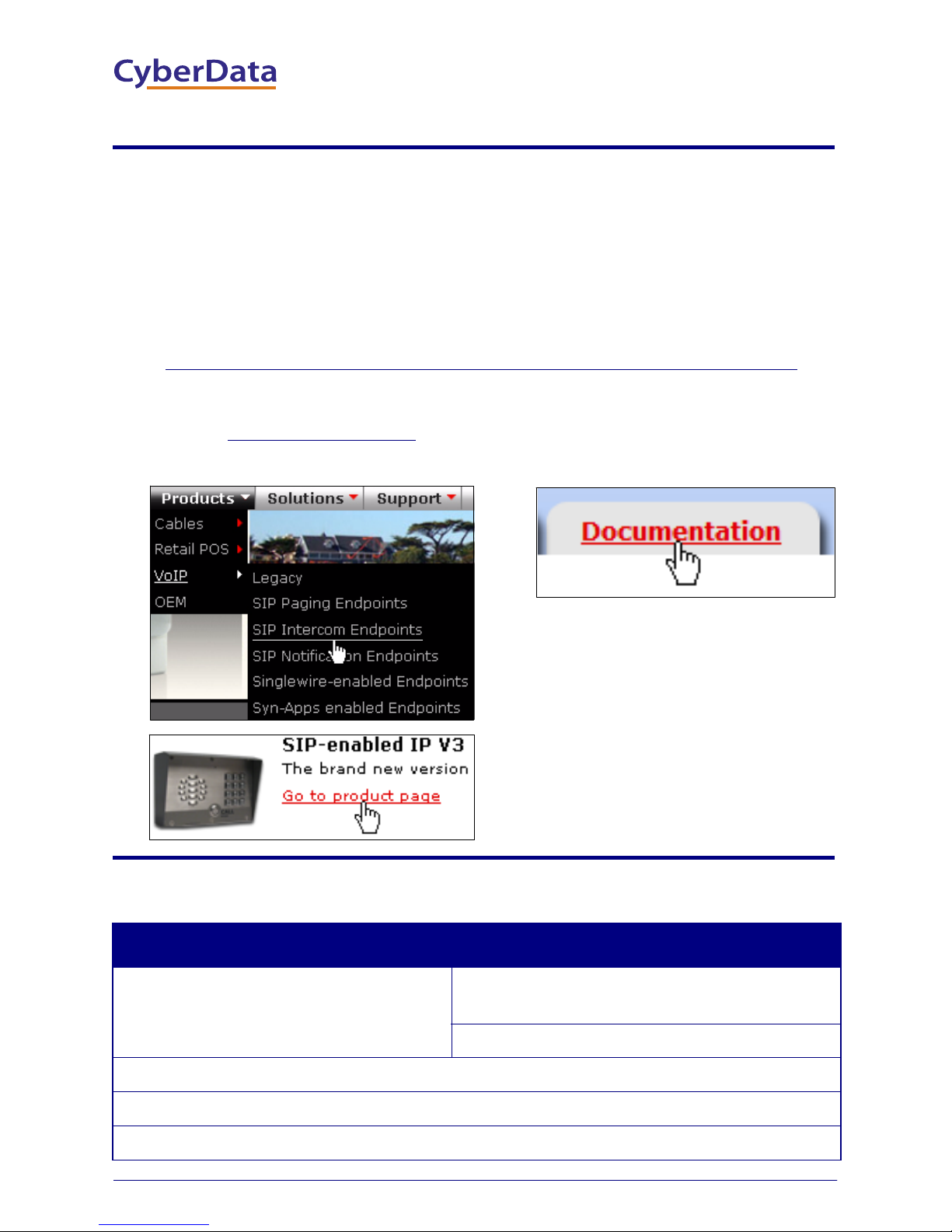
1.2. Download the current manual, otherwise known as an Operation Guide,
which is available on the Documentation page at the following website
address:
http://www.cyberdata.net/products/voip/digitalanalog/intercomkeypadv3/docs.html
Note You can also navigate to the Documentation page by going to
www.CyberData.net
the following figures:
and following the steps that are indicated by
2.0 Select Power Source
PoE Switch PoE Injector
Set PoE power type to Class 0 = 15.4W CAT6 cable recommended—
Make sure port is not in trunk mode
Set port to full duplex/ 100mbps
Spanning Tree Protocol (STP) must be disabled or Portfast enabled
Quick Start Guide 930521A
for longer distances
Be sure you are using a non-PoE switch or port
Page 2
3.0 Power Test
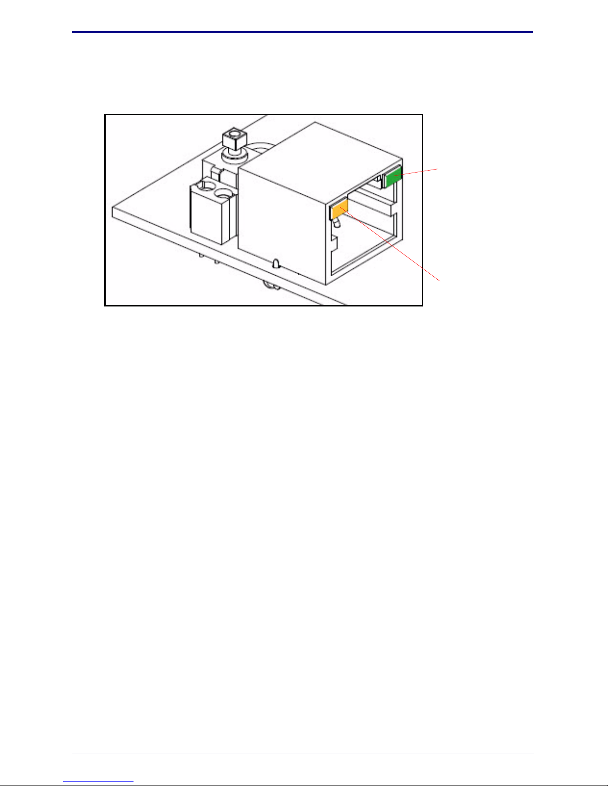
Link LED
Activity LED
VoIPon www.voipon.co.uk [email protected] Tel: +44 (0)1245 808195 Fax: +44 (0)1245 808299
3.1. Plug in the CyberData device and monitor the LED activity above the
ethernet port on the back of the Intercom. See the following figure:
3.2. The green Link LED blinks off once during the boot up process and then
comes on again and remains constant (solid green). The yellow Activity
LED may be blinking depending on the network activity.
During the initialization process, the green Call Button LED should come
on and be constant (solid green). After the Intercom has completed booting,
the LED will blink twice and then remain constant thereafter (either on or
off depending on whether or not the Button Lit When Idle setting is
enabled on the Device Configuration page).
Normally, the initialization process will take about 20 seconds. However, if
the device is set to use DHCP and no DHCP server is available, then the
device will retry for the amount of time specified in the DHCP Timeout in
seconds setting on the Network Configuration page before it falls back to
the stored static IP address (10.10.10.10 by default).
3.3. When the Intercom has completed the initialization process, press and hold
the RTFM switch (SW1 button) for 3 seconds to announce the IP address.
This concludes the power test. Go to Section 4.0, "Connecting to a Network
in a Test Environment".
Quick Start Guide 930521A
Page 3

4.0 Connecting to a Network in a Test Environment
VoIPon www.voipon.co.uk [email protected] Tel: +44 (0)1245 808195 Fax: +44 (0)1245 808299
Note The following connections are usually needed for this procedure:
•PC
• PoE switch or injector
•CyberData device
4.1. In a test environment, use a PC that is connected to the same switch as a
single CyberData device. Note the subnet of the test PC.
4.2. Use the CyberData Discovery Utility program to locate the device on the
network. You can download the Discovery Utility program from the
following website address:
http://www.cyberdata.net/support/voip/discovery_utility.html
4.3. Wait for initialization to complete before using the Discovery Utility
program to scan for a device. The device will show the current IP address,
MAC address, and serial number.
4.4. Select the device.
Note If the IP address of the device is in the same subnet of the PC, then
go to Step 4.7.
4.5. If the IP address of the device is different from the subnet of the PC, then
complete the following steps:
4.5.1. Click the Details tab.
4.5.2. Click Adv. Config to manually configure settings with an available IP
address in the same subnet.
Note A gateway address of 0.0.0.0 or a subnet address of
255.255.255.255 will prompt you to enter a valid address.
4.5.3. Click OK after you are finished making changes.
4.6. A dialog box will prompt you to click OK after confirming the configuration
changes and will ask you to wait while the device reboots. Please wait for
the device to power up and wait for the Discovery Utility program to find
the device on the network.
Quick Start Guide 930521A
Page 4
4.7. After the Discovery Utility program has located the device on the network,
VoIPon www.voipon.co.uk [email protected] Tel: +44 (0)1245 808195 Fax: +44 (0)1245 808299
click Launch Browser . When the IP address matches the subnet of the PC
that you are using to access the device, the Discovery Utility program will
be able to launch the browser window which is configured to the device’s IP
address.
4.8. Log on to the web interface by using the default username (admin) and
password (admin) to configure the device.
4.9. Perform an audio test by pressing the Test A ud io button that is located at
the bottom of the Device Configuration page. If the audio test message is
clearly audible, then your CyberData device is functioning properly.
4.10. The device is now ready to be set for your desired network configuration.
You may reference our IP-PBX specific configurations at the following
website address:
http://www.cyberdata.net/support/server/index.html
5.0 Contacting CyberData VoIP Technical Support
For quality assurance purposes, we ask that you please visit our website and
complete our Support Form which is available at the following website address:
http://www.cyberdata.net/support/contactsupportvoip.html
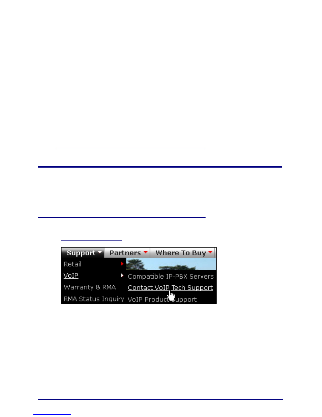
Note You can also navigate through menus to the Support Form by going to
www.CyberData.net
The Support Form initiates a ticket which CyberData uses for tracking customer
requests. Most importantly, the Support Form tells us which PBX system and
software version that you are using, the make and model of the switch, and other
important information. This information is essential for troubleshooting. Please
also include as much detail as possible in the Comments section of the Support
Form.
as shown in the following figure:
Requests for Returned Materials Authorization (RMA) numbers require an active
VoIP Technical Support ticket number. A product will not be accepted for return
without an approved RMA number.
Quick Start Guide 930521A
 Loading...