

Page 1
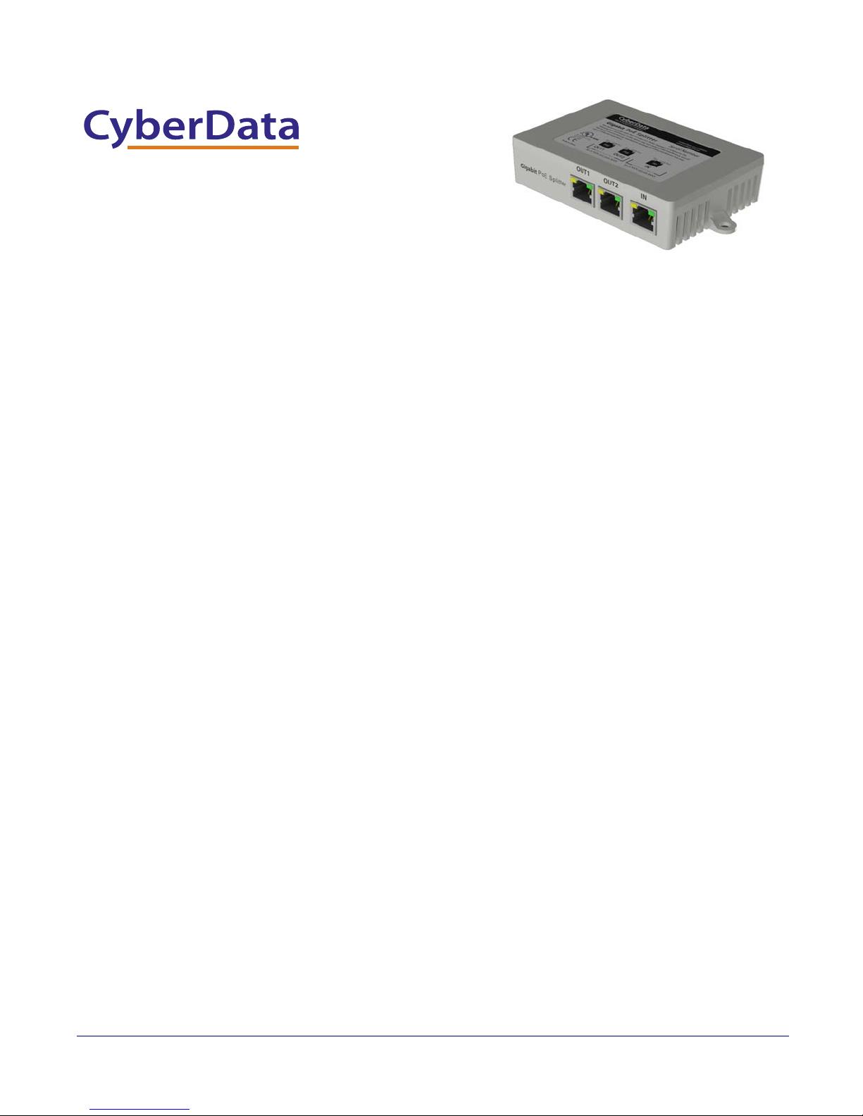
2-Port Gigabit Ethernet Switch
The IP Endpoint Company
Operations Guide
Part #011187
Document Part #930591A
for Firmware Version 1.0.0
CyberData Corporation
3 Justin Court
Monterey, CA 93940
(831) 373-2601
Page 2

PoE VoIP Intercom Operations Guide 930591A
Technical Support
The fastest way to get technical support for your VoIP product is to
submit a VoIP Technical Support form at the following website:
http://www.cyberdata.net/support/contactsupportvoip.html
Phone: (831) 373-2601, Ext. 333
Email: [email protected]
Fax: (831) 373-4193
Company and product information is at www.cyberdata.net.
Part # 011187
COPYRIGHT NOTICE:
© 2013, CyberData Corporation, ALL RIGHTS RESERVED.
This manual and related materials are the copyrighted property of CyberData Corporation. No part of
this manual or related materials may be reproduced or transmitted, in any form or by any means
(except for internal use by licensed customers), without prior express written permission of
CyberData Corporation. This manual, and the products, software, firmware, and/or hardware
described in this manual are the property of CyberData Corporation, provided under the terms of an
agreement between CyberData Corporation and recipient of this manual, and their use is subject to
that agreement and its terms.
DISCLAIMER: Except as expressly and specifically stated in a written agreement executed by
CyberData Corporation, CyberData Corporation makes no representation or warranty, express or
implied, including any warranty or merchantability or fitness for any purpose, with respect to this
manual or the products, software, firmware, and/or hardware described herein, and CyberData
Corporation assumes no liability for damages or claims resulting from any use of this manual or such
products, software, firmware, and/or hardware. CyberData Corporation reserves the right to make
changes, without notice, to this manual and to any such product, software, firmware, and/or
hardware.
OPEN SOURCE STATEMENT: Certain software components included in CyberData products are
subject to the GNU General Public License (GPL) and Lesser GNU General Public License (LGPL)
“open source” or “free software” licenses. Some of this Open Source Software may be owned by third
parties. Open Source Software is not subject to the terms and conditions of the CyberData
COPYRIGHT NOTICE or software licenses. Your right to copy, modify, and distribute any Open
Source Software is determined by the terms of the GPL, LGPL, or third party, according to who
licenses that software.
Software or firmware developed by CyberData that is unrelated to Open Source Software is
copyrighted by CyberData, subject to the terms of CyberData licenses, and may not be copied,
modified, reverse-engineered, or otherwise altered without explicit written permission from
CyberData Corporation.
TRADEMARK NOTICE: CyberData Corporation and the CyberData Corporation logos are
trademarks of CyberData Corporation. Other product names, trademarks, and service marks may be
the trademarks or registered trademarks of their respective owners.
The IP Endpoint Company
CyberData Corporation 930591A Operations Guide
Page 3

Revision Information
Revision 930591A, which corresponds to design version 1.0.0, was released on January 30, 2013.
Operations Guide 930591A CyberData Corporation
Page 4

Important Safety Instructions
1. Read these instructions.
2. Keep these instructions.
3. Heed all warnings.
4. Follow all instructions.
5. Do not use this apparatus near water.
6. Clean only with dry cloth.
7. Do not block any ventilation openings. Install in accordance with the manufacturer’s instructions.
8. Do not install near any heat sources such as radiators, heat registers, stoves, or other apparatus
(including amplifiers) that produce heat.
9. Only use attachments/accessories specified by the manufacturer.
10. Refer all servicing to qualified service personnel. Servicing is required when the apparatus has
been damaged in any way, such as power-supply cord or plug is damaged, liquid has been
spilled or objects have fallen into the apparatus, the apparatus has been exposed to rain or
moisture, does not operate normally, or has been dropped.
11. Prior to installation, consult local building and electrical code requirements.
CyberData Corporation 930591A Operations Guide
Page 5
Pictorial Alert Icons
GENERAL ALERT
Hazard Levels
Danger: Indicates an imminently hazardous situation which, if not avoided, will result in death or
serious injury. This is limited to the most extreme situations.
Warning: Indicates a potentially hazardous situation which, if not avoided, could result in death or
serious injury.
General Alert
This pictoral alert indicates a potentially hazardous situation. This alert will be
followed by a hazard level heading and more specific information about the
hazard.
Ground
This pictoral alert indicates the Earth grounding connection point.
Caution: Indicates a potentially hazardous situation which, if not avoided, could result in minor or
moderate injury. It may also alert users against unsafe practices.
Notice: Indicates a statement of company policy (that is, a safety policy or protection of property).
The safety guidelines for the equipment in this manual do not purport to address all the safety issues
of the equipment. It is the responsibility of the user to establish appropriate safety, ergonomic, and
health practices and determine the applicability of regulatory limitations prior to use. Potential safety
hazards are identified in this manual through the use of words Danger, Warning, and Caution, the
specific hazard type, and pictorial alert icons.
CyberData Corporation 930591A Operations Guide
Page 6

Contents
1.0 Installation ............................................................................................... 1
2.0 Checklist ................................................................................................. 1
3.0 Installation .............................................................................................. 2
4.0 Powering on the Switch ........................................................................... 2
5.0 Powering on the Switch ........................................................................... 3
6.0 Network Connection ................................................................................ 3
7.0 Technical Specifications .......................................................................... 5
Appendix A The Standard RJ-45 Introduction 6
A.1 The Standard Cable, RJ-45 Pin Assignment .......................................... 7
i
1.1 Features ................................................................................................................... 1
3.1 Installation Method ................................................................................................... 2
3.2 Desktop or Shelf Installation ..................................................................................... 2
Appendix B Mounting 8
B.1 Mounting ................................................................................................. 8
Appendix C Typical Installation 9
C.1 Typical Installation ................................................................................... 9
Operations Guide 930472C CyberData Corporation
Page 7

1.0 Installation
The switch is a three port Gigabit PoE (Power over Ethernet) Repeater Ethernet switch. The switch
is in full compliance with the IEEE802.3 at standard with one PD (Power Device) port and two PSE
(Power Source Equipment) ports.
This switch can work through receiving power from another PoE switch or equipment through the PD
port. The PSE ports can supply power to other PoE devices (30W maximum). The combined power
output from both PSE ports can be up to 30W, but it also depends upon the PD port supply. For
example, if the PD supply port only delivers 15W, then the two PSE ports can only deliver up to
approximately 13W.
The switch will provide a simple, economic standard for high performance GBit network applications
that allows for the splitting/dividing of one PoE network drop. The 2-Port Gigabit Ethernet Switch is
an ideal choice to promote the department and working group performance. The switch provides
simple and understandable LED indicator lights on the front panel, so that you can quickly judge the
working state of the switch and help to diagnose the network failure.
1.1 Features
1
• Supports PoE IEEE802.3at compliant
• Supports PoE IEEE802.3af compliant
• Support two power source equipment to supply external devices
• Supports IEEE802.3x flow control for full-duplex mode and back pressure for half-duplex mode
• Support ports Auto MDI/MDIX
• 8K entry MAC address table of the switch with auto-learning and auto-aging
• LED indicators for monitoring PD, PSE, Link / Activity
• No external power supply design
2.0 Checklist
Before you start installing your equipment, verify that the package contains the following:
• The Gigabit POE Repeater Switch
• This User Manual
Please notify your supplier immediately if any of the previously items are missing or damaged.
Operations Guide 930591A CyberData Corporation
Page 8
3.0 Installation
3.1 Installation Method
The site where you install the switch may greatly affect its performance. When installing, please take
the following into consideration.
• Install the switch in a cool, dry place. See technical specifications for the acceptable
temperature and humidity operating ranges.
• Install the switch on a secure, level surface that can support its weight (at least 1Kg).
Alternatively, the switch can be applied to any smooth dry surface using furnished stick-on tape.
• Leave at least 10cm of space at the front and rear of the switch to ensure adequate ventilation.
3.2 Desktop or Shelf Installation
2
When installing the switch on a shelf on desktop, make sure that the previously mentioned
guidelines in
Section 3.1, "Installation Method "are followed for adequate ventilation.
4.0 Powering on the Switch
The switch is powered by your existing central POE Switch. No additional power supply
is required. Simply plug your cable from your central POE switch into the PD port of the
switch and your switch will power on for use.
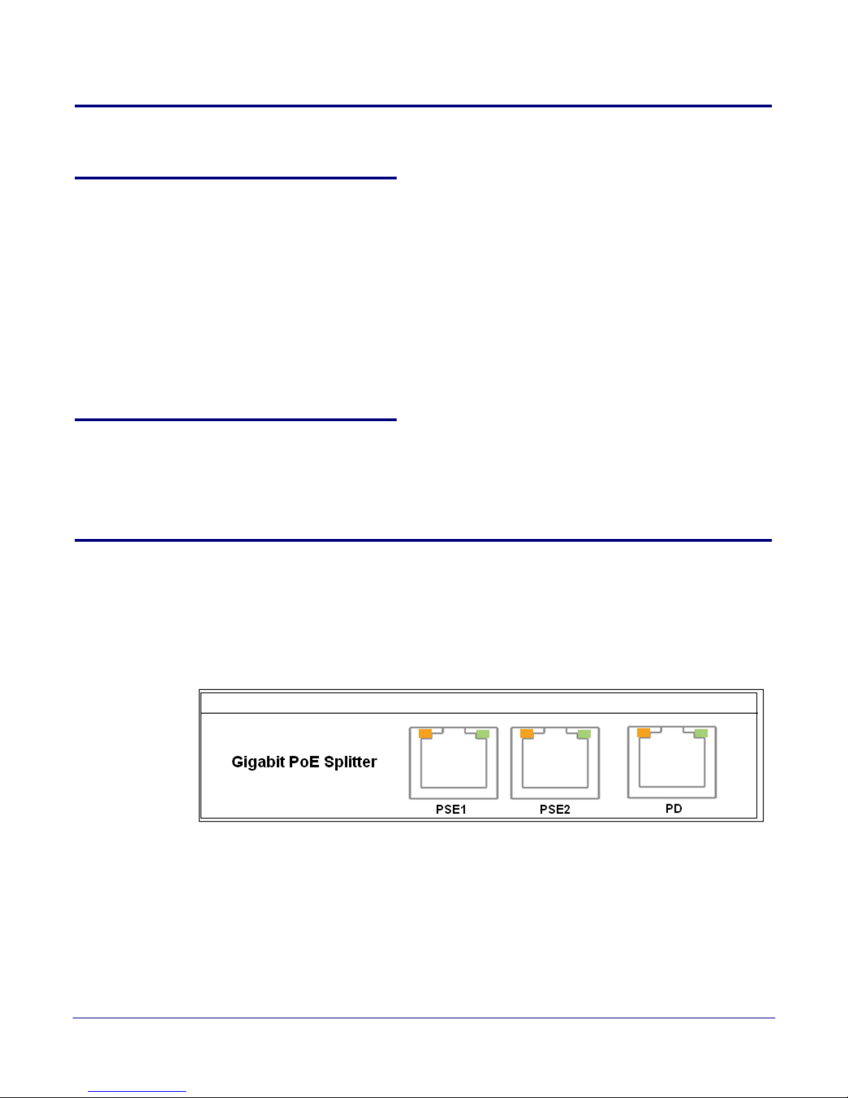
Figure 1-1. Front Panel of the Switch
Operations Guide 930591A CyberData Corporation
Page 9
5.0 Powering on the Switch
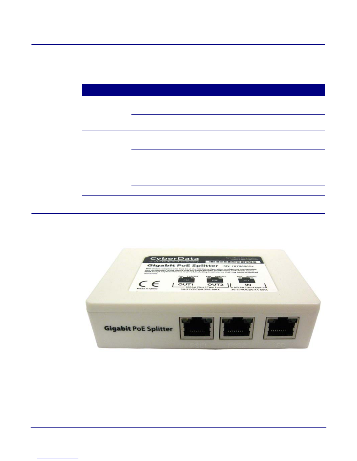
Figure 1-2. Powering on the Switch
LED Status Description
PD (Orange) ON Switch has a connection from the PD port to the PSE device.
OFF Connection to the PSE device is not present.
PSE (Orange) ON PD device such as IP phone is connected to the port and
OFF PD device is not connected or no power is being drawn from
Power has been successfully applied.
No power has been applied to the switch.
drawing power.
the switch.
3
Link/Act (Green) ON
Blink Traffic is present on port.
OFF
6.0 Network Connection
A valid link is established.
No link has been established.
Figure 1-3. Front Panel of Switch
Operations Guide 930591A CyberData Corporation
Page 10
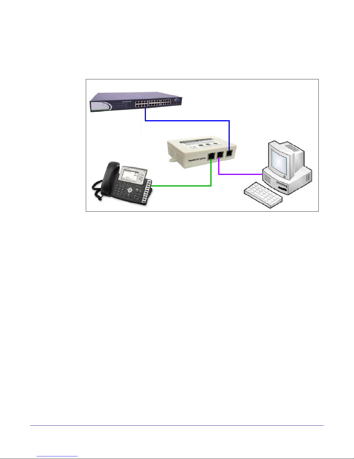
Connect your devices (computer, router, switch, IP Phone, Wireless Access Point, IP Camera etc.) to
the ports with a CAT-5/CAT-5e/CAT-6 network cable. Since the switch supports Auto MDI/MDI-X, you
can use either a straight through or cross-over network cable.
Figure 1-4. Typical Installation of the Switch
4
• Connect the switch from the PD port to your central Gigabit PoE Switch.
• Connect your IP Phone from the PSE port on the switch.
• Connect your computer or other networking device to any of the PSE2 ports on the switch.
Operations Guide 930591A CyberData Corporation
Page 11

7.0 Technical Specifications
5
Standards
IEEE802.3af, IEEE802.3x, IEEE802.3ab,
IEEE802.3az
10BASE-T: UTP category 3,4,5 cable
(maximum 100m)
Network Media (Cable)
100BASE-T: UTP category 5,5e cable
(maximum 100m)
1000BASE-T: UTP category 5e,6 cable
(maximum 100m)
Number of Ports 3 x 10/100/1000Mbps Auto-Negotiation ports
LED
indicators
10/100/1000M Link/Act
Other PD, PSE
Transfer Method Store-and-Forward
Switching Capacity 6G
MAC Address Learning Automatically learning, automatically Update 8K
Frame Filtering and Forward
Rate
148800pps
Operating Temperature: 0 ℃ ~40 ℃
Environment
Storage Temperature: -10 ℃ ~70 ℃
Operating Humidity: 10%~90% non-condensing
Storage humidity: 5%~90% non-condensing
Operations Guide 930591A CyberData Corporation
Page 12

Appendix A: The Standard RJ-45 Introduction
Regarding cable-making methods, a cable which does not meet the standards of the sequence data
will make the data transmission speed slow, unstable and even be blocked.
standard RJ-45 jack and the connector (Figure A-1) and pin definition:
Figure A-1. Standard RJ-45 Jack / Connector
Table A-1. RJ-45 Connector Pin Definitions
Pin Number Signal
1_TX1 +(PoE Power+)
6
Ta bl e A-1 represents the
2 _TX1 - (PoE Power+)
3 _RX1 + (PoE Power-)
4_TX2 +
5_TX2 --
6 _RX1 - (PoE Power-)
7_RX2 +
8_RX2 -
Operations Guide 930591A CyberData Corporation
Page 13
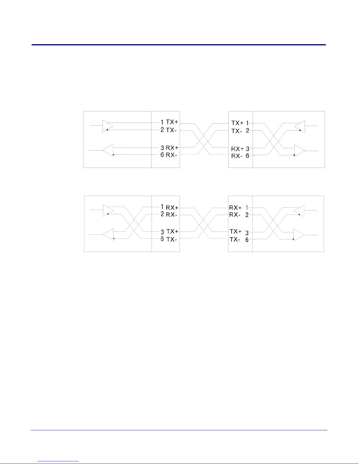
The Standard Cable, RJ-45 Pin Assignment
A.1 The Standard Cable, RJ-45 Pin Assignment
The following figures shows a straight cable and a crossover cable connection. Use a straight cable
connection to connect switch/Hub or other devices:
Figure A-2. Straight cable for the switch (uplink MDI-II port) to switch/Hub or other devices
connection.
Figure A-3. Crossover cable for switch (MDI-X port) to switch/hub or other network devices
(MDI-X port) connection.
7
Operations Guide 930591A CyberData Corporation
Page 14
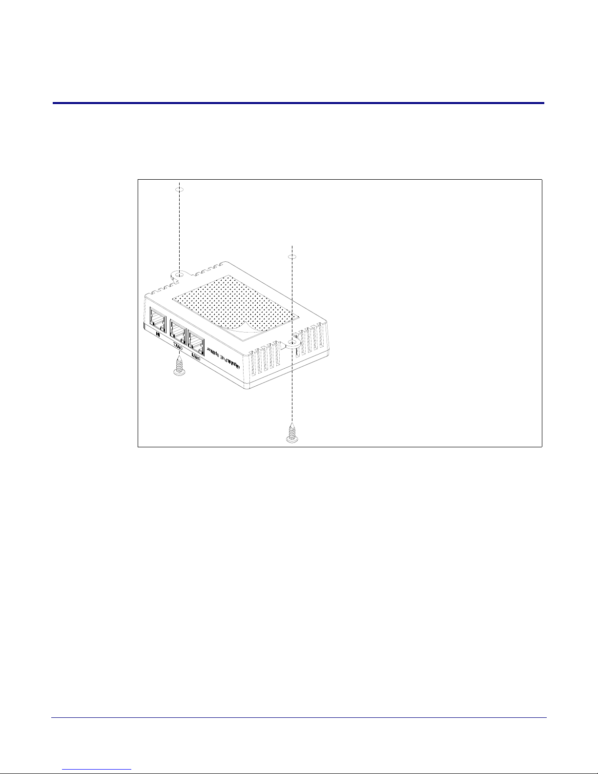
Appendix B: Mounting
Mounting Option:
1. Mounting Screw
Pre-drill two 1/8" holes
Use supplied screws
2. Adhesive
Peel o adhesive backing and attach to desk
B.1 Mounting
Figure B-1 shows a mounting option for the 2-Port Gigabit Ethernet Switch.
8
Figure B-1. Mounting
Operations Guide 930591A CyberData Corporation
Page 15
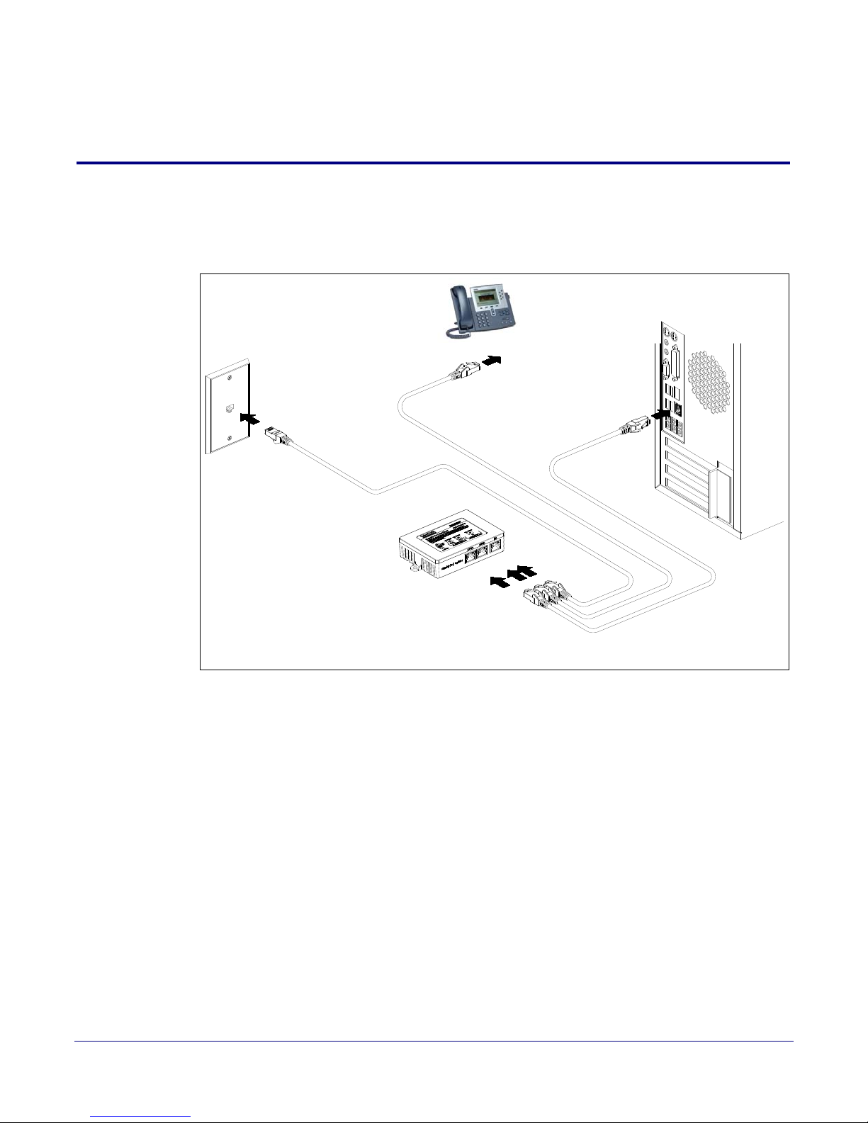
Appendix C: Typical Installation
802.3af or
802.3at
PoE Power for Phone
Non-PoE
C.1 Typical Installation
Figure C-1 shows a typical installation setup for the 2-Port Gigabit Ethernet Switch.
Figure C-1. Typical Installation
9
Operations Guide 930591A CyberData Corporation
 Loading...