

Installation Quick Reference
Singlewire-enabled
VoIP V2 Loudspeaker Amplifier
(Wireless)
011115
Quick Reference 930352A © 2010, CyberData Corporation, ALL RIGHTS RESERVED© 2010, CyberDa ta Corporation, ALL RIGH TS RESERVED 930352A Quick Reference
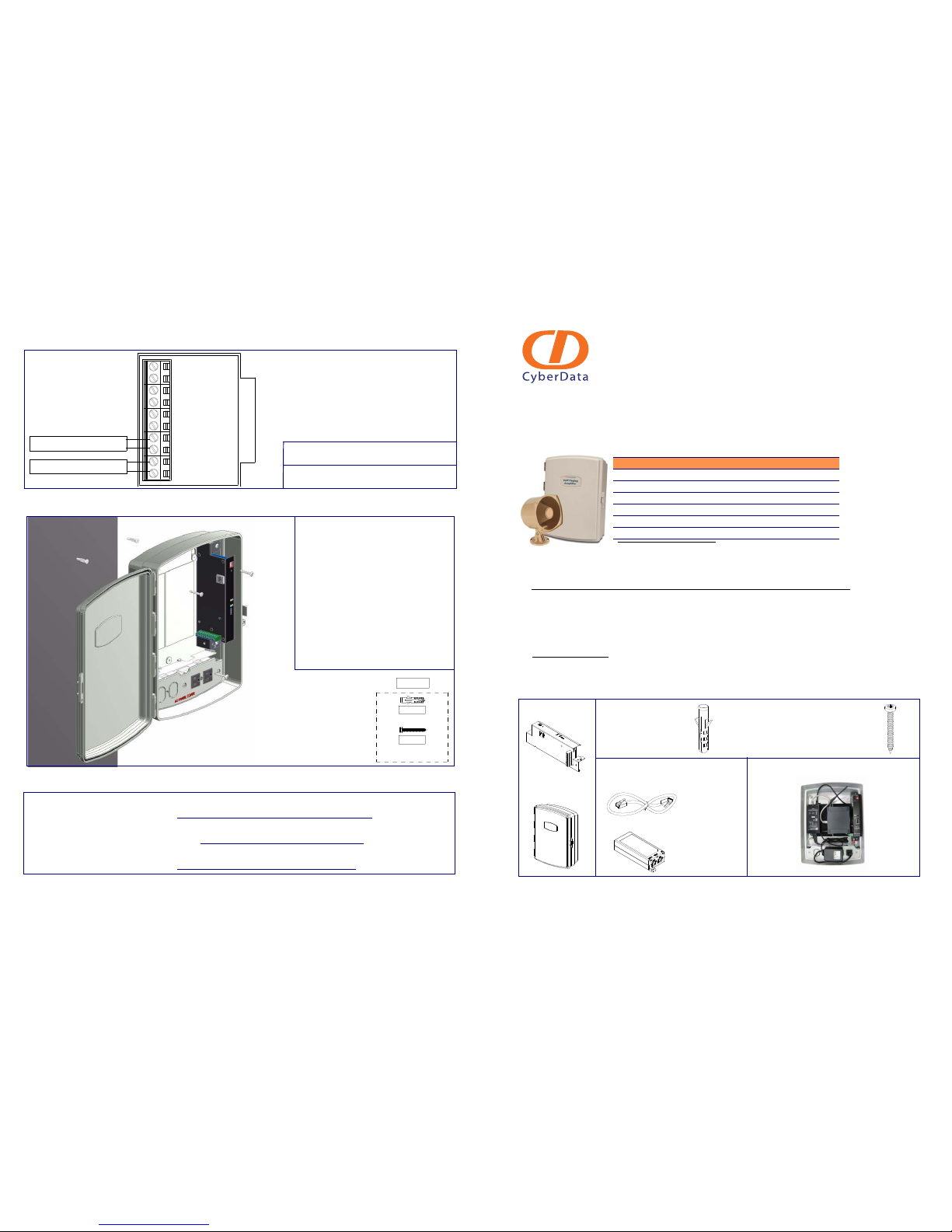
Connections
Mounting the Enclosure
Contacting CyberData
1-Sense (+)
2-GND
3-Relay COM
4-Relay NO
5-Line-In(+)
6-Line-In(-)
7-Line-Out(+)
8-Line-Out(-)
9-Spkr Out(+)
10-Spkr Out (-)
CLASS II WIRING
Speaker Connection
Line-Out Connection
Note: The Button/Relay and Line-In features are
not supported with the Singlewire firmware.
Note: Line-Out is 10k Ohm at 2Vpp.
Speaker output is 8 Ohm.
To mount the enclosure:
1. Prepare holes for the screws.
2. Plug in t he power adapte r and use the
green Power light to verify that the
power is on.
3. Plug the Ethernet cable into the VoIP V2
Loudspeaker Amplifier. The yellow
Link light verifies the network
connection.
4. For wall mounting, use the three
#6 x 1-1/4-inch Pan Head Phillip screws
to secure the speaker.
071057A
PHILLIP SCREW (3x)
#6x1 1/4" PAN HEAD
#6 PLASTIC ANCHOR (3x)
151014
531032
Sales: (831) 373-2601 ext. 334
Support: 831-373-2601 ext. 333
Web: http://www.cyberdata.net/support/contactsupportvoip.html
RMA Dept: (831) 373-2601 ext. 136
Email: RMA@CyberData.net
RMA Status: http://www.cyberdata.net/support/rmastatus.html
Warranty information is available at:
Web: http://www.cyberdata.net/support/warranty/index.html
Corporate Headquarters
CyberData Corporation
2555 Garden Road
Monterey, CA 93940, USA
Phone: 831-373-2601
Fax: 831-373-4193
www.CyberData.net
The Singlewire-enabled VoIP V2 Loudspeaker Amplifier is compatible with InformaCast Version 4.0 and higher.
Getting Started
•Download the Singlewire-enabled VoIP V2 Loudspeaker Amplifier Operations Guide from the Documents page at:
http://www.cyberdata.net/products/voip/digitalanalog/singlewireloudspeakerampv2/docs.html
• Create a plan for the locations of your paging amplifiers.
• Prior to installation, consult local building and electrical code requirements.
Wiring the 125V AC Plug
V2 Loudspeaker Amplifier Parts
Parameter Factory Default Setting
IP Addressing DHCP
IP Address
a
a. Default if there is not a DHCP server present.
10.10.10.10
Web Access Username admin
Web Access Password admin
Subnet Mask
a
255.0.0.0
Default Gateway
a
10.0.0.1
The green wire with the yellow stripe is a ground connection for Electrostatic Discharge (ESD) protection,
and should not be removed
.
To wire the 125V AC plug, consult a licensed electrician and the local building codes in your area.
(1) Assembly (1) Wall Mounting Kit
(3) #6 Plastic Anch ors (3) #6 x 1-1/4-inc h Pan Head Phillip Screws
(1) Enclosure
(2) CAT 5e/CAT6 cable
Optional Parts (not included)
View Inside of th e Enclosure
(1) PoE Power Injector
© 2010, CyberData Corporation, ALL RIGHTS RESERVED 930352A Quick Reference Quick Reference 930352A © 2010, CyberData Corporation, ALL RIGHTS RESERVED
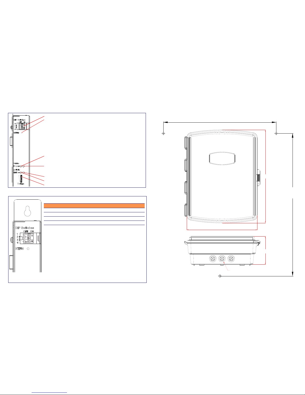
Features
DIP Switch Settings
DIP Switches
Speaker Volume
Network Link LED (GREEN/YELLOW)
Status LED (GREEN)
A steady LED confirms that the V2 Loudspeaker Amplifier is operational. The LED will blink during a page when it is online.
Network Activity LED (GREEN)
Power L ED (GREEN/BLUE)
The power LED is a steady green in low power mode and a steady blue during high power
mode. The power LED will only blink either during a boot up or a phone call.
RTFM Switch
To broadcast a V2 Loudspeaker Amplifier’s current IP address, press the RTFM switch on
the V2 Loudspeaker Amplifier for one second, and then release the switch to hear the IP
address announcement.
To restore the factory defaults, complete the following steps:
1. Press and hold the RTFM switch for eight seconds. The V2 Loudspeaker Amplifier will
announce the words, “restoring defaults”, and then announce the words, “rebooting”.
2. Release the RTFM switch. The V2 Loudspeaker Amplifier settings
will be restored to the factory default settings.
User Hardware Dip Switch and Jumper Settings
DIP Switch Default Setting Description
1 OFF Sets PoE for 802.3af class.
2 N/A Not applicable for power setting.
3 ON Switch mode current set to LOW.
4 OFF Low gain amplifier setting.
Note: High power PoE mode conforms to IEEE 802.3at draft 3.0.
7.938
[201.63]
6.281 [159.54]
Dimensions are in Inches [Millimeters]
Dimensions and Mounting Template
14.500
[368.30]
10.875 [276.23]
4.375
[111.13]
Cable Grommets (3 PLCS)
Dimensions are in Inches [Millimeters]
 Loading...