

Page 1
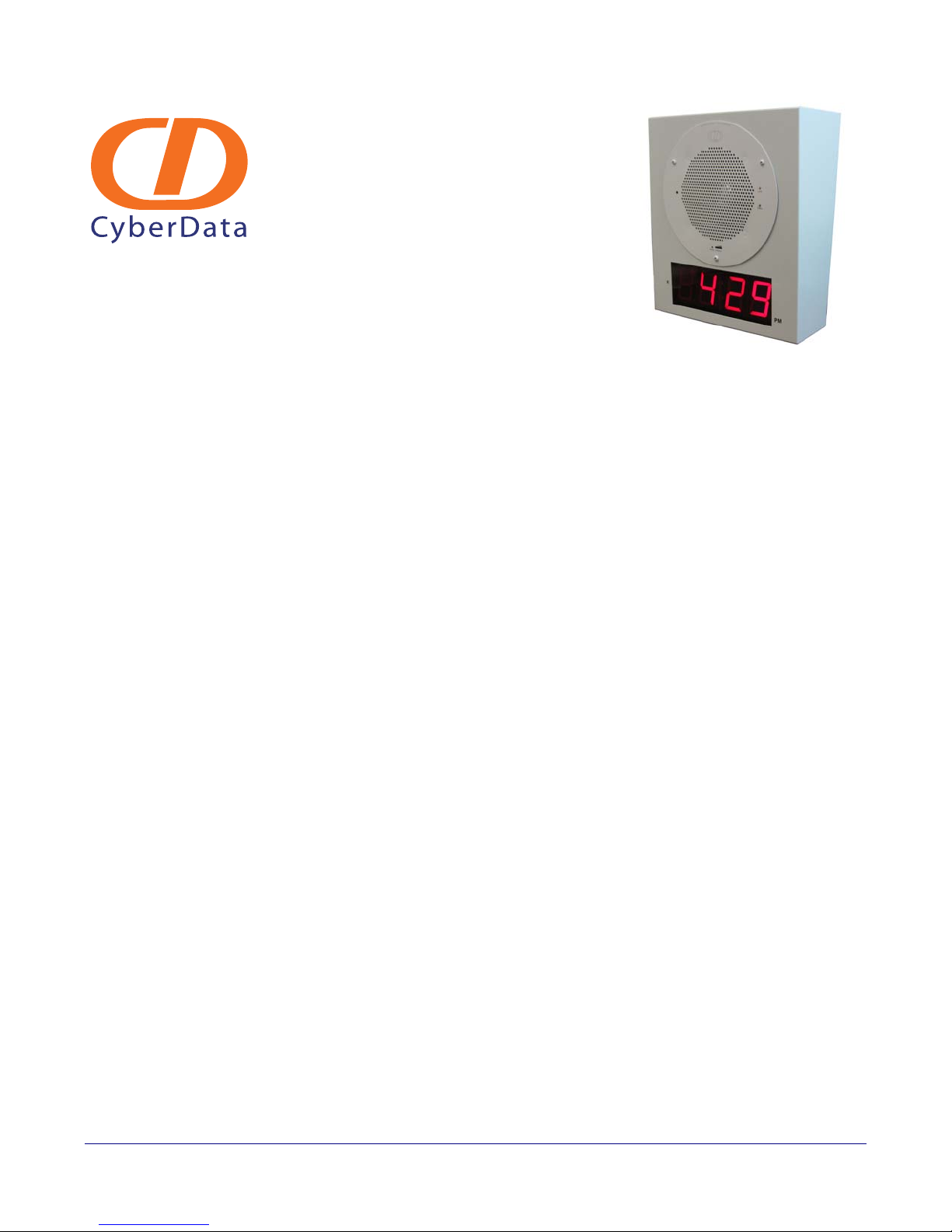
VoIP Clock Kit Wall Mount
Adapter
Operations Guide
Part #011100*, RAL 9002, Gray White, Standard
Part #011101, RAL 9003, Signal White, Optional
*Replaces #011023
Document Part #930283F
CyberData Corporation
2555 Garden Road
Monterey, CA 93940
(831) 373-2601
Page 2

PoE VoIP Speaker Operations Guide 930283F
Phone: (831) 373-2601
Technical Support Ext. 333
[email protected]
Fax: (831) 373-4193
Company and product information at www.cyberdata.net
Part # 011023
COPYRIGHT NOTICE:
© 2010, CyberData Corporation, ALL RIGHTS RESERVED.
This manual and related materials are the copyrighted property of CyberData Corporation. No part
of this manual or related materials may be reproduced or transmitted, in any form or by any means
(except for internal use by licensed customers), without prior express written permission of
CyberData Corporation. This manual, and the products, software, firmware, and/or hardware
described in this manual are the property of CyberData Corporation, provided under the terms of
an agreement between CyberData Corporation and recipient of this manual, and their use is subject
to that agreement and its terms.
DISCLAIMER: Except as expressly and specifically stated in a written agreement executed by
CyberData Corporation, CyberData Corporation makes no representation or warranty, express or
implied, including any warranty or merchantability or fitness for any purpose, with respect to this
manual or the products, software, firmware, and/or hardware described herein, and CyberData
Corporation assumes no liability for damages or claims resulting from any use of this manual or
such products, software, firmware, and/or hardware. CyberData Corporation reserves the right to
make changes, without notice, to this manual and to any such product, software, firmware, and/or
hardware.
OPEN SOURCE STATEMENT: Certain software components included in CyberData products are
subject to the GNU General Public License (GPL) and Lesser GNU General Public License (LGPL)
“open source” or “free software” licenses. Some of this Open Source Software may be owned by
third parties. Open Source Software is not subject to the terms and conditions of the CyberData
COPYRIGHT NOTICE or software licenses. Your right to copy, modify, and distribute any Open
Source Software is determined by the terms of the GPL, LGPL, or third party, according to who
licenses that software.
Software or firmware developed by CyberData that is unrelated to Open Source Software is
copyrighted by CyberData, subject to the terms of CyberData licenses, and may not be copied,
modified, reverse-engineered, or otherwise altered without explicit written permission from
CyberData Corporation.
TRADEMARK NOTICE: CyberData Corporation and the CyberData Corporation logos are
trademarks of CyberData Corporation. Other product names, trademarks, and service marks may
be the trademarks or registered trademarks of their respective owners.
Operations Guide 930283F CyberData Corporation
Page 3

Revision Information
Revision 930283F, was updated on 7-15-2010 and has the following changes:
• Adds information about the following 01 numbers:
Part #011100*, RAL 9002, Gray White, Standard
Part #011101, RAL 9003, Signal White, Optional
*Replaces #011023
Operations Guide 930283F CyberData Corporation
Page 4
Important Safety Instructions
GENERAL ALERT
GENERAL ALERT
1. Read these instructions.
2. Keep these instructions.
3. Heed all warnings.
4. Follow all instructions.
5. Do not use this apparatus near water.
6. Clean only with dry cloth.
7. Do not block any ventilation openings. Install in accordance with the manufacturer’s
instructions.
8. Do not install near any heat sources such as radiators, heat registers, stoves, or other apparatus
(including amplifiers) that produce heat.
9. Do not defeat the safety purpose of the polarized or grounding-type plug. A polarized plug has
two blades with one wider than the other. A grounding type plug has two blades and a third
grounding prong. The wide blade or the third prong are provided for your safety. If the
provided plug does not fit into your outlet, consult an electrician for replacement of the obsolete
outlet.
10. Protect the power cord from being walked on or pinched particularly at plugs, convenience
receptacles, and the point where they exit from the apparatus.
11. Only use attachments/accessories specified by the manufacturer.
12. Refer all servicing to qualified service personnel. Servicing is required when the apparatus has
been damaged in any way, such as power-supply cord or plug is damaged, liquid has been
spilled or objects have fallen into the apparatus, the apparatus has been exposed to rain or
moisture, does not operate normally, or has been dropped.
13. Prior to installation, consult local building and electrical code requirements.
Warning
Electrica l Hazard: This product should be installed by a licensed electric ian
according to al l local electric al and building codes .
Warning
Electrica l Hazard: To prevent injury, this apparatus mus t be securely attached to
the floor/wall in accordance with the installation instructions.
Operations Guide 930283F CyberData Corporation
Page 5
Pictorial Alert Icons
GENERAL ALERT
Hazard Levels
Danger: Indicates an imminently hazardous situation which, if not avoided, will result in death or
serious injury. This is limited to the most extreme situations.
Warning: Indicates a potentially hazardous situation which, if not avoided, could result in death or
serious injury.
General Alert
This pictoral alert indicat es a potentially hazardous situation. This alert will be
followed by a haza rd level heading and more specific information about the
hazard.
Ground
This pictora l alert indicates the Earth grounding connection point.
Caution: Indicates a potentially hazardous situation which, if not avoided, could result in minor or
moderate injury. It may also alert users against unsafe practices.
Notice: Indicates a statement of company policy (that is, a safety policy or protection of property).
The safety guidelines for the equipment in this manual do not purport to address all the safety
issues of the equipment. It is the responsibility of the user to establish appropriate safety, ergonomic,
and health practices and determine the applicability of regulatory limitations prior to use. Potential
safety hazards are identified in this manual through the use of words Danger, Warning, and
Caution, the specific hazard type, and pictorial alert icons.
Operations Guide 930283F CyberData Corporation
Page 6

Contents
Chapter 1 Product Overview 1
1.1 How to Identify this Product ................................................................................................................2
1.2 Typical System Installation ...................................................................................................................3
1.3 Product Features .....................................................................................................................................4
1.4 Product Specifications ...........................................................................................................................5
1.5 Dimensions .............................................................................................................................................6
Chapter 2 Installing the VoIP Clock Kit Wall Mount Adapter 7
2.1 Pre-Mounting Connections ...................................................................................................................7
2.2 Verifying Operation of the Clock Kit Adapter .................................................................................12
2.3 The Clock Kit Adapter Battery ...........................................................................................................15
2.4 Mounting the Clock Kit Wall Mount Adapter .................................................................................19
i
2.1.1 Install JP1 Prior to Clock Kit Installation .................................................................................7
2.1.2 Moving the Clock Connector Cover Plate ...............................................................................8
2.1.3 Connecting the Clock to the Speaker .......................................................................................9
2.1.4 Connecting Power to the Speaker ...........................................................................................10
2.2.1 Identifying the VoIP Clock Kit Jumpers ................................................................................12
2.2.2 Power-Up Test ...........................................................................................................................13
2.3.1 JP1 Battery Enable Jumper for Real-Time Clock Operation ................................................15
2.3.2 Checking the Battery Power Level of the Clock Kit Adapter .............................................16
2.3.3 Replacing the Clock Kit Battery ..............................................................................................16
2.3.4 Seconds Digits Blinking Fast ...................................................................................................18
2.4.1 Parts List .....................................................................................................................................19
2.4.2 Mounting ....................................................................................................................................20
2.4.3 Uploading the Firmware ..........................................................................................................21
2.4.4 Setting the Time on the Clock Kit Adapter ...........................................................................21
2.4.5 Confirm that the Speaker is Operational and Linked to the Network .............................21
Appendix A Setting up a TFTP Server 22
A.1 Set up a TFTP Server ..........................................................................................................................22
A.1.1 In a LINUX Environment ........................................................................................................22
A.1.2 In a Windows Environment ...................................................................................................22
Appendix B Troubleshooting/Technical Support 23
B.1 Frequently Asked Questions (FAQ) ..................................................................................................23
B.2 Documentation .....................................................................................................................................23
B.3 Contact Information ............................................................................................................................23
B.4 Warranty ...............................................................................................................................................24
B.4.1 Warranty & RMA Returns within the United States ...........................................................24
B.4.2 Warranty & RMA Returns Outside of the United States ....................................................24
B.4.3 Spare in the Air Policy .............................................................................................................25
B.4.4 Return and Restocking Policy .................................................................................................25
B.4.5 Warranty and RMA Returns Page ..........................................................................................25
Index 26
Operations Guide 930283F CyberData Corporation
Page 7
1 Product Overview
GENERAL ALERT
The Clock Kit enables the CyberData V2 VoIP Ceiling Speaker to be upgraded to a highly visible
public address device with a time display.
Note The Cyberdata speaker is not included with this kit.
The large display characters are easily read and adjust for ambient light conditions. Time sync is
performed by NTP and a built-in real -time clock.
Power is supplied by the CyberData V2 Speaker from a single PoE connection.
Note Prior to installation, create a plan for the locations of your SiP VoIP and PoE Speaker.
General Alert
Consult local building and electrical code re quirements pr ior to installation.
1
Operations Guide 930283F CyberData Corporation
Page 8

1.1 How to Identify this Product
CLOCK KIT,FOR VoIP SPEAKER V2,
WALL MOUNT
011000A / 021035B
000000001
Model number
WWW.CYBERDATA.NET
To identify the VoIP Clock Kit Wall Mount Adapter, look for a model number label similar to the one
shown in
• 011100*, RAL 9002, Gray White, Standard Color
• 011101, RAL 9003, Signal White, Optional Color
*Replaces 011023.
Figure 1-1. The model number on the label should be one of the following:
Figure 1-1. Model Number Label
Product Overview
How to Identify this Product
2
Operations Guide 930283F CyberData Corporation
Page 9
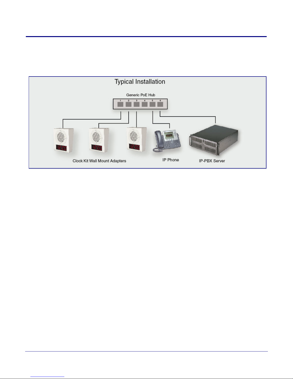
1.2 Typical System Installation
Figure 1-2 illustrates a typical installation for the SiP VoIP and PoE Speakers.
Figure 1-2. Typical Installation
Product Overview
Typical System Installation
3
Operations Guide 930283F CyberData Corporation
Page 10
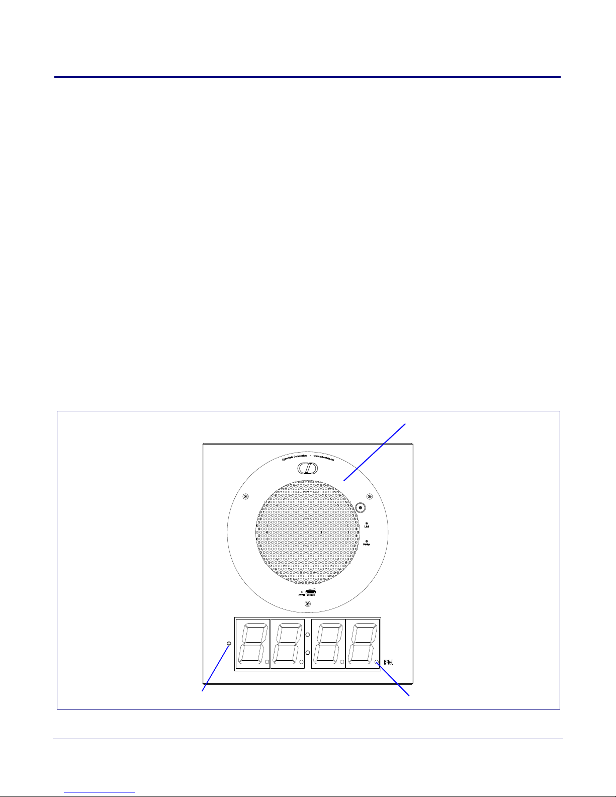
1.3 Product Features
CyberData Part #011021 or #011022
PM LED
Ambient light detector
(sold separately)
● Easy wall or ceiling installation
● Mounting kit included
● Electrogalvinized steel construction
● RoHS compliant
● Keyhold for easy installation
● Part number (Wall Mount): 011023
● Part number (Flush Mount): 011024
● Top and bottom cable channels
● 2.3-inch sized digits
● 12 or 24 hour format
● NTP time source
● Battery backed up real-time clock
● Auto ambient light adjustment
● PM LED
● Two years warranty
Product Overview
Product Features
4
Figure 1-3 shows the location of some of the features of the VoIP Clock Kit Wall Mount Adapter.
Figure 1-3. Feature Locations
Operations Guide 930283F CyberData Corporation
Page 11

1.4 Product Specifications
Category Specification
Operating temperature -30 to 55 C (-22 to 131 F)
Power Input (J1) PoE 802.3af (as per IEEE 802.3af standard from a UL listed
limited power source)
44-57 VDC at 350mA
Product Overview
Product Specifications
5
or Alternate Power Input
(Terminal Block J4)
Time Source NTP Server or battery backed-up real-time clock.
Warranty 2 years limited
Dimensions 13.5” [343mm] x 11.8” [300mm] x 5.4” [137mm]
Weight 8.8 lbs. [4 kg]
Part number 011100*, RAL 9002, Gray White, Standard Color
10-20 VDC at 500mA
Battery life estimated to be approximately seven years.
011101, RAL 9003, Signal White, Optional Color
*Replaces 011023.
Operations Guide 930283F CyberData Corporation
Page 12
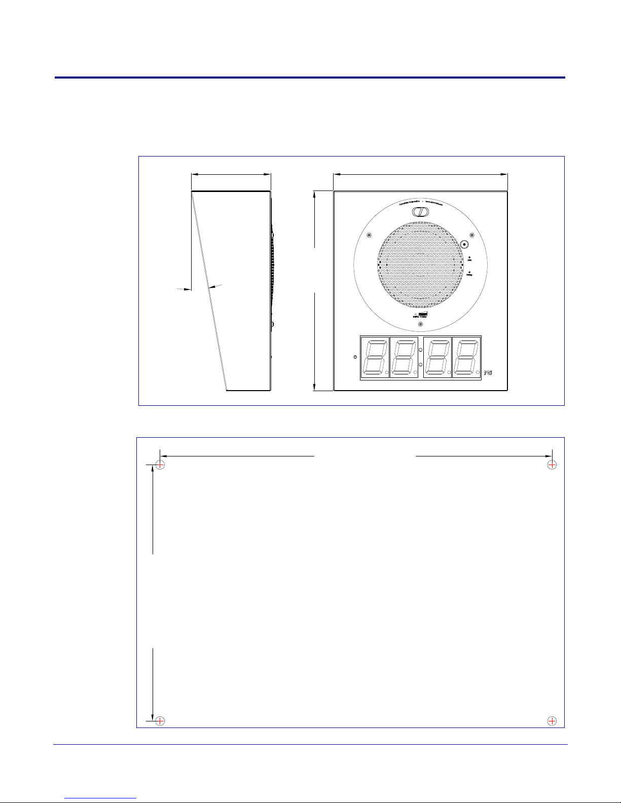
1.5 Dimensions
10.70 [271.8]
7.00 [177.8]
Dimensions are in Inches [mm]
Figure 1-4 shows the dimensions for the VoIP Clock Kit Wall Mount Adapter.
Figure 1-4. Dimensions
Product Overview
Dimensions
6
10°
5.4 [137]
11.8 [300]
13.5 [343]
Dimensions are in Inches [Millimeter]
Figure 1-5. Dimensions
Operations Guide 930283F CyberData Corporation
Page 13
2 Installing the VoIP Clock Kit Wall Mount
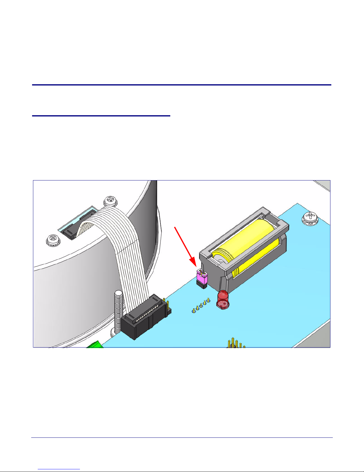
JP1
Adapter
2.1 Pre-Mounting Connections
2.1.1 Install JP1 Prior to Clock Kit Installation
To enable the battery for real-time clock operation, install a jumper on JP1 as shown in Figure 2-6.
Note This jumper ensures that the clock will not lose the time setting in the event of a power
outage.
Figure 2-6. Jumper JP1
7
Operations Guide 930283F CyberData Corporation
Page 14
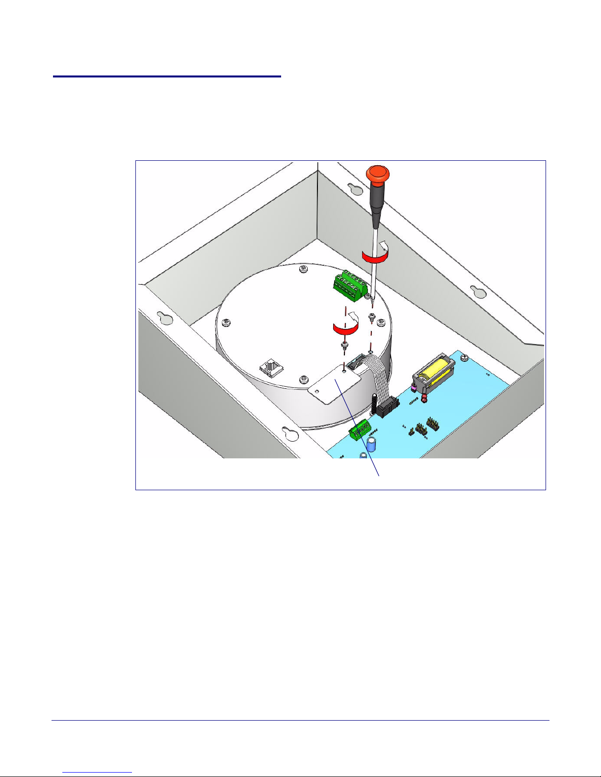
2.1.2 Moving the Clock Connector Cover Plate
Cover plate
Move the clock connector cover plate to prepare the Clock Kit for pre-mounting connections.
See Figure 2-7.
Figure 2-7. Moving the Clock Connector Cover Plate
Installing the VoIP Clock Kit Wall Mount Adapter
Pre-Mounting Connections
8
To remove the clock connector cover plate,
1. Unscrew and remove the two attachment cover screws.
2. Rotate the clock connector cover plate 180 degrees as shown in Figure 2-7.
3. Screw and tighten the cover screws to secure the cover plate in place.
Operations Guide 930283F CyberData Corporation
Page 15
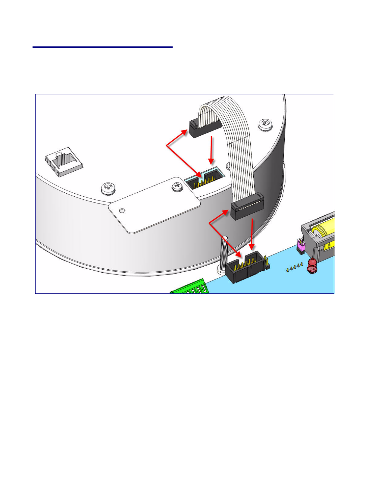
2.1.3 Connecting the Clock to the Speaker
Figure 2-8 illustrates how to connect the ribbon cable to the clock and the speaker.
Figure 2-8. Connecting the Clock to the Speaker
Installing the VoIP Clock Kit Wall Mount Adapter
Pre-Mounting Connections
9
Operations Guide 930283F CyberData Corporation
Page 16
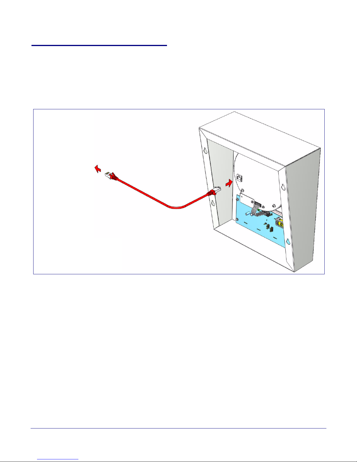
2.1.4 Connecting Power to the Speaker
To PoE N e t wo r k
Figure 2-9 and Figure 2-10 illustrates two possible ways to connect power to the speaker.
Note Prior to mounting, you can route the Ethernet cable through the back or through the slots at
the top or bottom of the Clock Kit Adapter.
Figure 2-9. Connecting Power—PoE
Installing the VoIP Clock Kit Wall Mount Adapter
Pre-Mounting Connections
10
Operations Guide 930283F CyberData Corporation
Page 17
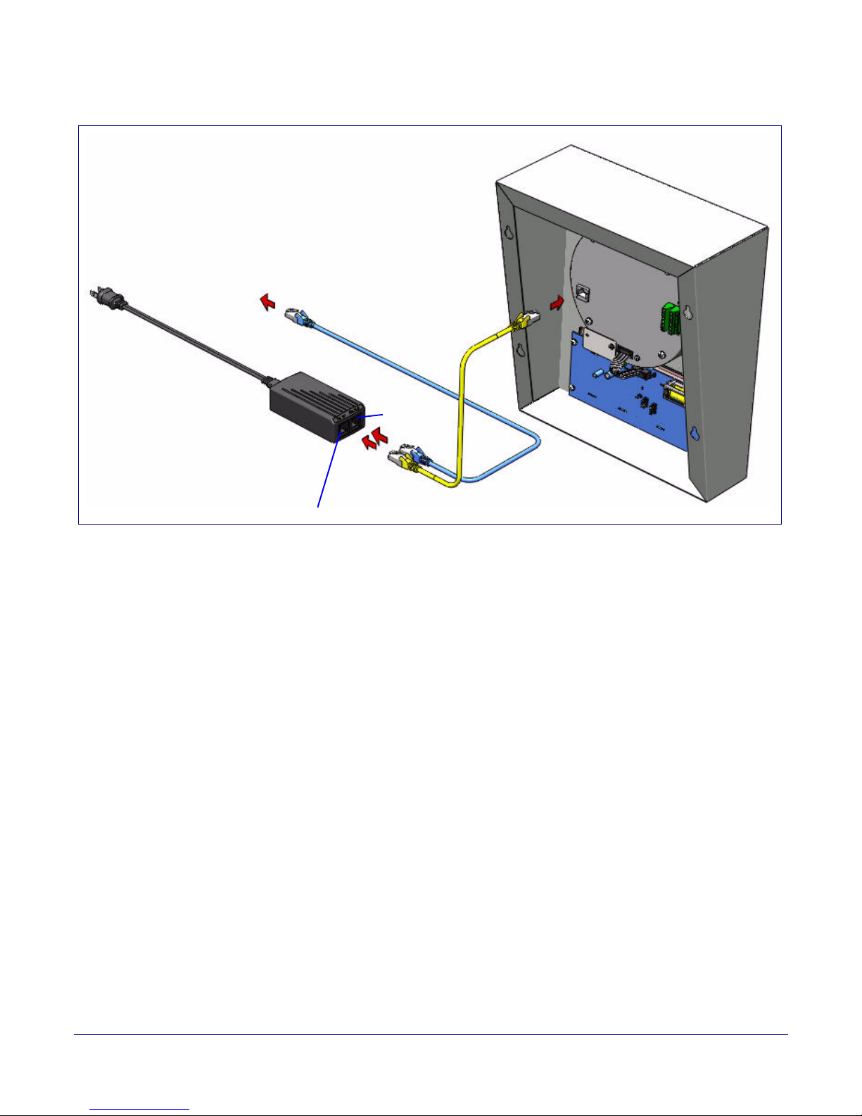
Installing the VoIP Clock Kit Wall Mount Adapter
Device
Ethernet
Optional power injector
(CyberData # 010867A)
To N e t wo r k
Pre-Mounting Connections
Figure 2-10. Connecting Pow e r—Optional Power Injector
11
Operations Guide 930283F CyberData Corporation
Page 18
Installing the VoIP Clock Kit Wall Mount Adapter
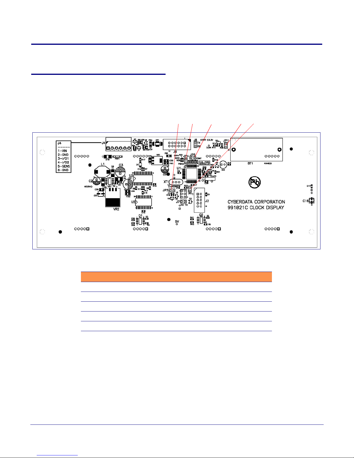
JP1 JP2JP3 JP4 JP5
Verifying Operation of the Clock Kit Adapter
2.2 Verifying Operation of the Clock Kit Adapter
2.2.1 Identifying the VoIP Clock Kit Jumpers
See Figure 2-11 and Table 2-1 to identify the jumper locations and functions.
Figure 2-11. Jumper Locations
12
Table 2-1. Jumper Functions
Jumper Function
JP1 Battery - Connect
JP2 Manufacturing - Open
JP3 Manufacturing - Open
JP4 Manufacturing - Open
JP5 Manufacturing - Open
Note Prior to installing the Clock Kit, make sure that JP1 is installed. This powers the Real Time
Clock from the battery. If you do not, the clock will loose it's time when the power is
disconnected.
Operations Guide 930283F CyberData Corporation
Page 19
2.2.2 Power-Up Test
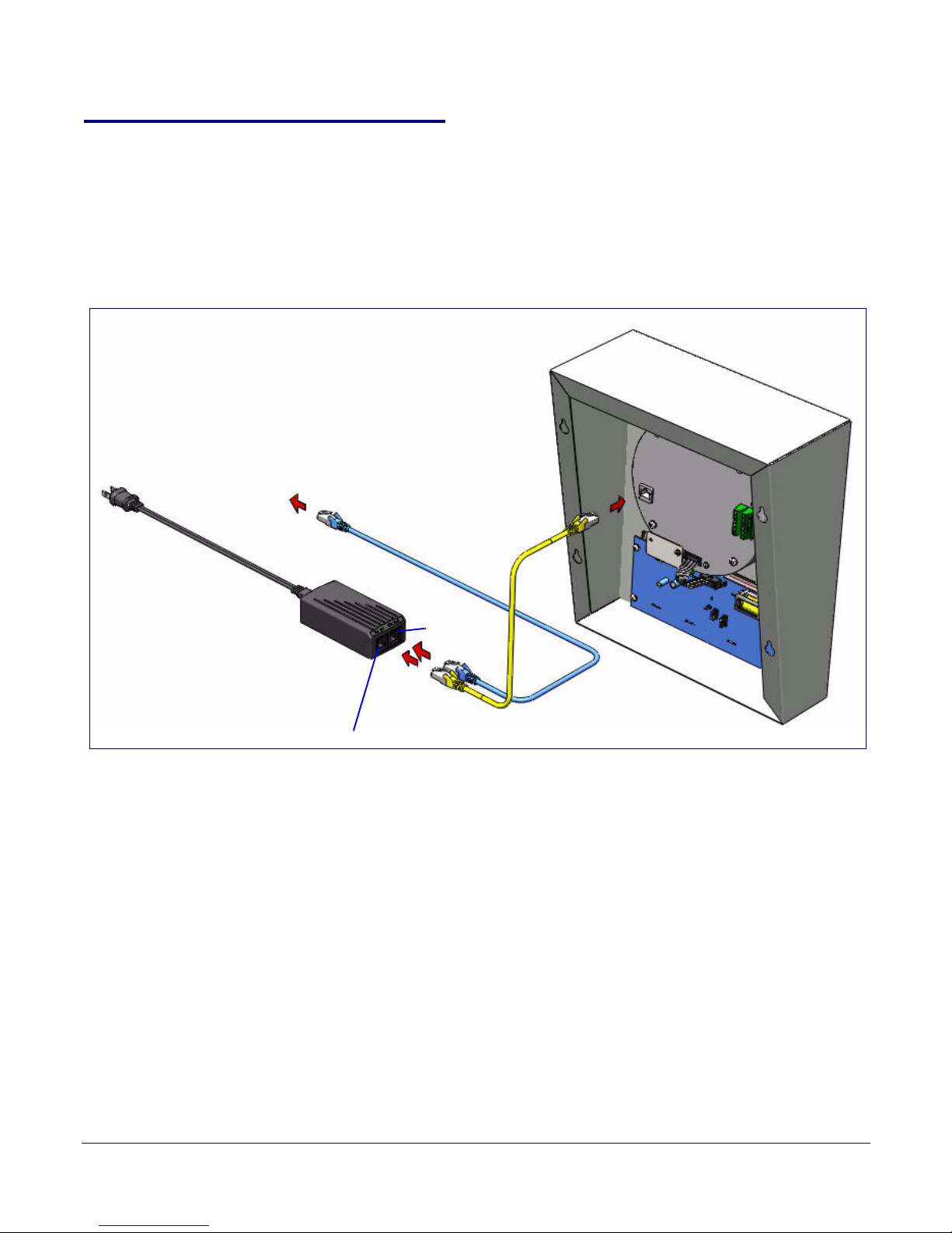
Device
Ethernet
Optional power injector
(CyberData # 010867A)
To N e t wo r k
To perform a power up test,
1. Connect power to the speaker as shown in Figure 2-12.
Note Prior to mounting, you can route the Ethernet cable through the back or through the slots at
the top or bottom of the Clock Kit Adapter.
Installing the VoIP Clock Kit Wall Mount Adapter
Verifying Operation of the Clock Kit Adapter
Figure 2-12. Connecting Power
13
Operations Guide 930283F CyberData Corporation
Page 20

2. After connecting power, you will see one of the boot-up messages indicated in Tab le 2-2.
Message Meaning Action
Installing the VoIP Clock Kit Wall Mount Adapter
Verifying Operation of the Clock Kit Adapter
Table 2-2. Clock Kit Boot-Up Messages
14
8888 Normal start-up
message.
None.
Note: On the Clock Kit display, you will see the numbers 8888 for one second before
displaying the time that is in memory.
E01 Time error This would normally occur at manufacturing first Power On, or at subsequent Power On if
the battery was low or dead. If it occurs more frequently, contact CyberData support.
Note: If there is an Invalid Time Error, then you will see E 01 on the display for one second
and the time will be reset to 00:00.
E02 Low battery Replace the battery. See Section 2.3.3, "Replacing the Clock Kit Battery".
Note: If the Clock Kit battery is low, then at power up, you will see E 02 on the display for
one second before displaying the time that is in memory.
Operations Guide 930283F CyberData Corporation
Page 21
Installing the VoIP Clock Kit Wall Mount Adapter
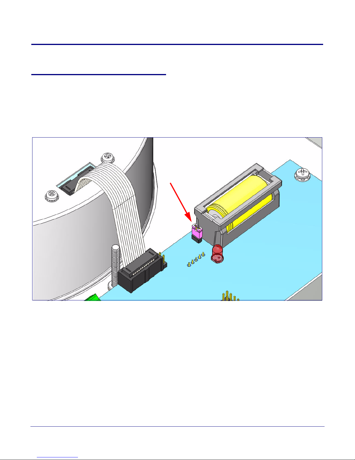
JP1
The Clock Kit Adapter Battery
2.3 The Clock Kit Adapter Battery
2.3.1 JP1 Battery Enable Jumper for Real-Time Clock Operation
To enable the battery for real-time clock operation, install a jumper on JP1 as shown in Figure 2-13.
Note This jumper ensures that the clock will not lose the time setting in the event of a power
outage.
Figure 2-13. Jumper JP1
15
Operations Guide 930283F CyberData Corporation
Page 22

Installing the VoIP Clock Kit Wall Mount Adapter
The Clock Kit Adapter Battery
2.3.2 Checking the Battery Power Level of the Clock Kit Adapter
To check the battery power level of the Clock Kit Adapter,
1. Disconnect and reconnect power to the VoIP Speaker.
2. On the Clock Kit display, you will see the numbers 8888 for one second and then one of the
following will occur:
● If the battery power level is good, then the Clock Kit display will resume showing the time that
is in memory.
● If the Clock Kit battery is low, then you will see E 02 on the display for one second before
displaying the time that is in memory.
Note If there is an Invalid Time Error, then you will see E 01 on the display for one second and
the time will be reset to 00:00.
2.3.3 Replacing the Clock Kit Battery
16
2.3.3.1 Battery Type
You should use a Lithium-Ion size 2/3A type battery with minimum 1000 mA-hr rating for the
Clock Kit Adapter.
Acceptable replacements:
● Panasonic CR123A
● Duracell DL2/3A
● Sanyo CR17335SE
2.3.3.2 Battery Life
The Lithium-Ion CR-123 battery in the Clock Kit Adapter should last for approximately seven years.
Operations Guide 930283F CyberData Corporation
Page 23
2.3.3.3 Replacing the Battery
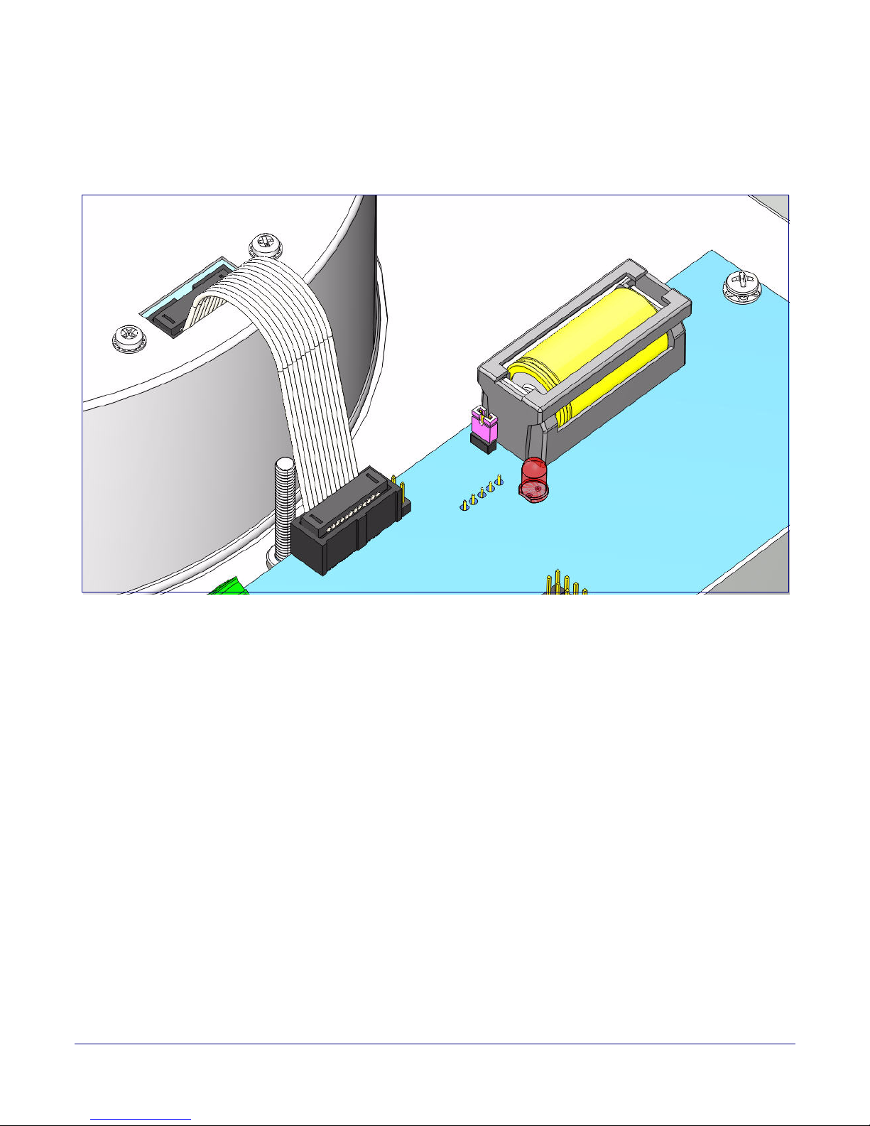
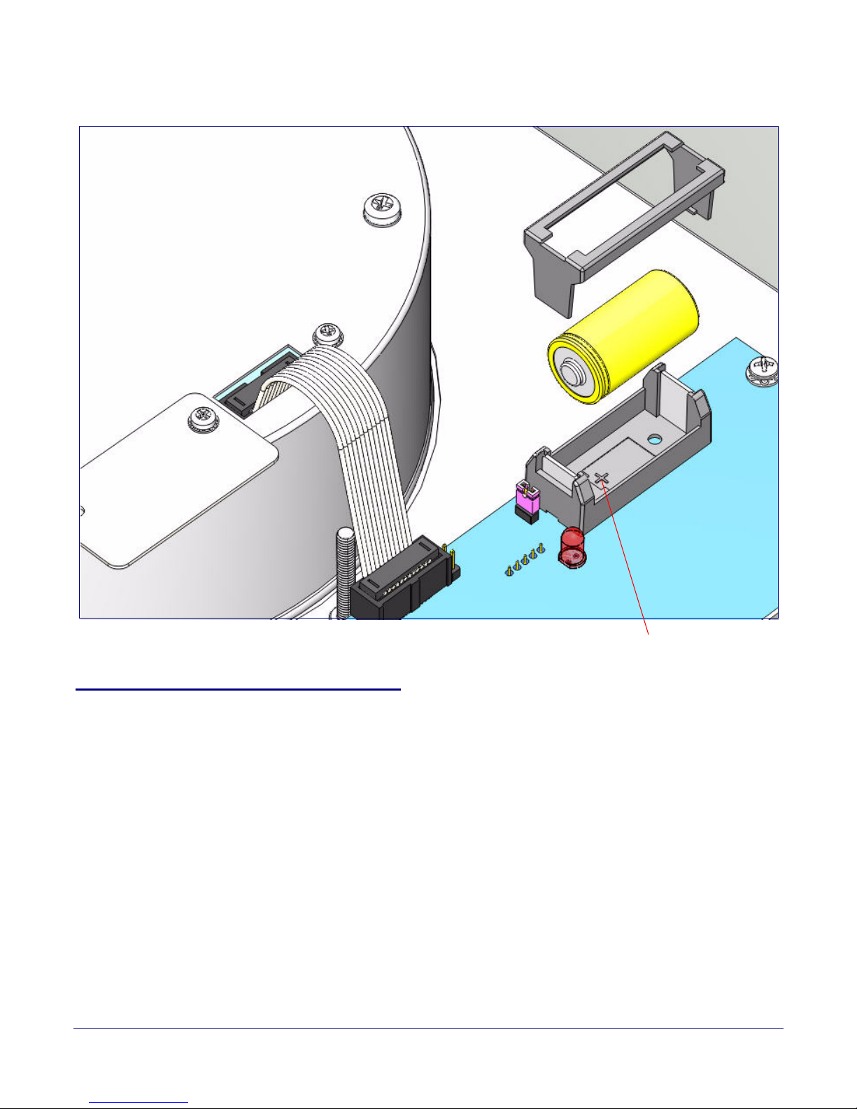
Figure 2-14 and Figure 2-15 illustrates how to locate and replace the Clock Kit battery.
Installing the VoIP Clock Kit Wall Mount Adapter
Figure 2-14. Clock Kit Battery Location
17
The Clock Kit Adapter Battery
Operations Guide 930283F CyberData Corporation
Page 24
Installing the VoIP Clock Kit Wall Mount Adapter
Positive (+)
Figure 2-15. Clock Kit Battery Replacement
18
The Clock Kit Adapter Battery
2.3.4 Seconds Digits Blinking Fast
If the seconds digits on the Clock Kit display are blinking fast, then this means that the speaker has
not communicated for more than one hour.
Operations Guide 930283F CyberData Corporation
Page 25
Installing the VoIP Clock Kit Wall Mount Adapter
Mounting the Clock Kit Wall Mount Adapter
2.4 Mounting the Clock Kit Wall Mount Adapter
2.4.1 Parts List
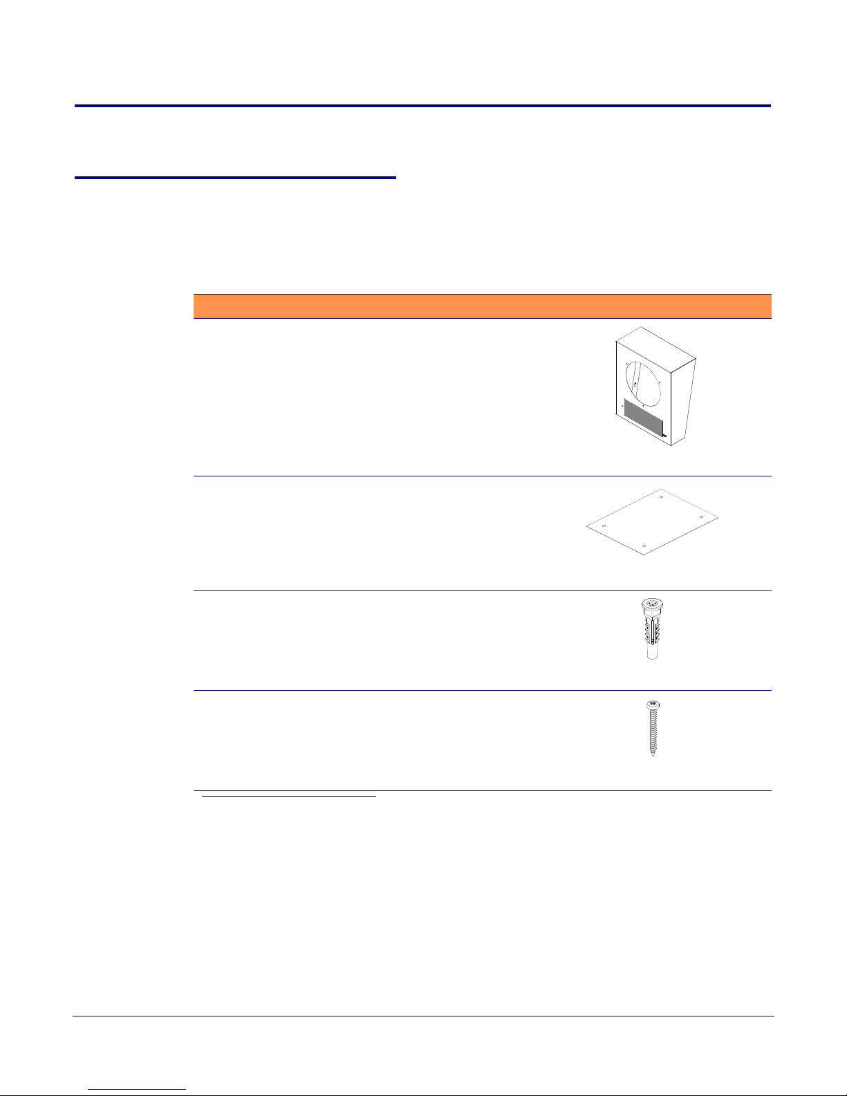
Before you install the clock kit wall mount adapter, make sure that you have received all of the parts.
Refer to
Tab le 2-3.
Table 2-3. Drywall Mounting Kita
Quantity Part Name Illustration
1 Wall Mount Adapter
19
1 Placemat containing template for wall mount
adapter and screw holes
4 Plastic Ribbed Anchors
4 #8 Sheet Metal Screws
bc
a.The drywall mou nting kit is part of the accessory kit.
b.The ceiling speaker wall-mounted adapter screws will be include d in the cei ling speaker kit.
c.The installation template for the Wall Mount Adapter is located on the Installation Quick Reference Guide that is included in the packaging with each speaker.
Operations Guide 930283F CyberData Corporation
Page 26
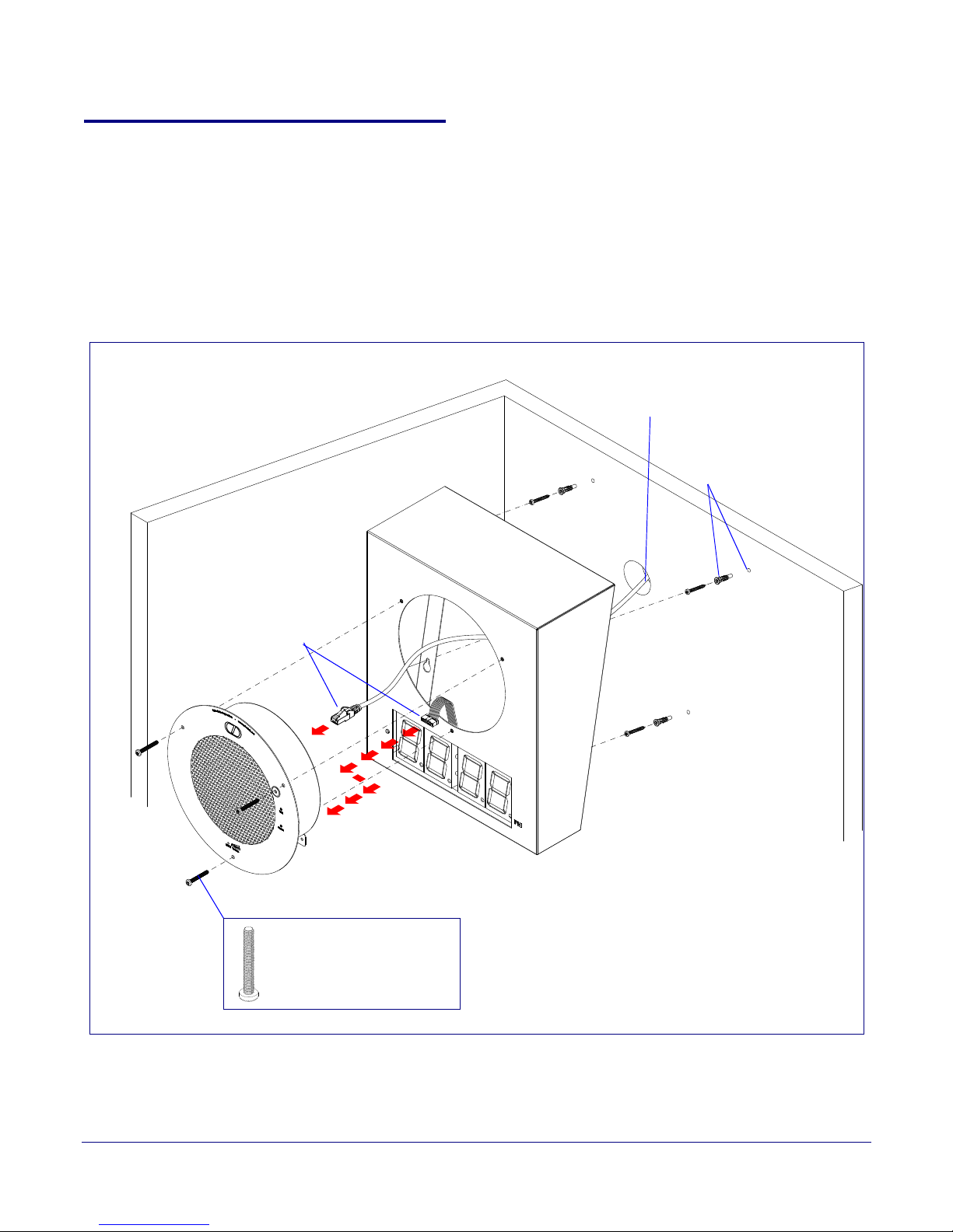
2.4.2 Mounting
Network cable routed through a wall into the
rear of the Clock Kit Wall Mount Adapter.
Step 1
Step 2
Step 3
Step 4
(3) 8-32 x 1 1/4” Mounting
Screws (from the Ceiling
Speaker Drop Ceiling
Mounting Kit)
To mount a Clock Kit Wall Mount Adapter,
● Place the four plastic-ribbed anchors in the holes you prepared.
● Screw the four #8 sheet metal screws into the four plastic-ribbed anchors.
Installing the VoIP Clock Kit Wall Mount Adapter
Mounting the Clock Kit Wall Mount Adapter
1. Use the template on the Installation Quick Reference placemat for the Clock Kit Wall Mount
Adapter to drill four holes in the wall for the anchors and screws. See
Figure 2-16. Clock Kit Wall Mount Adapter Installation
Figure 2-16.
20
2. Position the Clock Kit Wall Mount Adapter over the four #8 sheet metal screws.
Operations Guide 930283F CyberData Corporation
Page 27

3. Make sure that the ribbon and the ethernet cable are both connected to the IP speaker assembly.
If they are not connected, then see the following sections:
• Section 2.1.2, "Moving the Clock Connector Cover Plate"
• Section 2.1.3, "Connecting the Clock to the Speaker"
• Section 2.1.4, "Connecting Power to the Speaker"
Note You can route the Ethernet cable through the back or through the slots at the top or bottom
of the wall mount adapter.
4. Position the IP speaker assembly into the clock kit wall mount adapter so that the IP speaker
assembly screw holes align with the mounting holes in the clock kit wall mount adapter.
● Use three 8-32 x 1 1/4” mounting screws (from the Ceiling Speaker Drop Ceiling Mounting Kit)
to secure the IP speaker assembly to the wall mount adapter.
2.4.3 Uploading the Firmware
Depending on which speaker you are using, please see one of the following documents:
●
VoIP V2 Speaker Operation Guide
●
VoIP V2 Talkback Speaker Operation Guide
Installing the VoIP Clock Kit Wall Mount Adapter
Mounting the Clock Kit Wall Mount Adapter
21
These documents are available at the following website address:
http://www.cyberdata.net/products/voip/digitalanalog/clockkit/docs.html
2.4.4 Setting the Time on the Clock Kit Adapter
Depending on which speaker you are using, please see one of the following documents:
●
VoIP V2 Speaker Operation Guide
●
VoIP V2 Talkback Speaker Operation Guide
These documents are available at the following website address:
http://www.cyberdata.net/products/voip/digitalanalog/clockkit/docs.html
2.4.5 Confirm that the Speaker is Operational and Linked to the Network
Depending on which speaker you are using, please see one of the following documents:
●
VoIP V2 Speaker Operation Guide
●
VoIP V2 Talkback Speaker Operation Guide
These documents are available at the following website address:
http://www.cyberdata.net/products/voip/digitalanalog/clockkit/docs.html
Operations Guide 930283F CyberData Corporation
Page 28

Appendix A: Setting up a TFTP Server
A.1 Set up a TFTP Server
Upgrading the VoIP Clock Kit Wall Mount Adapter firmware requires a TFTP server on which you
access the Web interface where you can upload the firmware files.
A.1.1 In a LINUX Environment
To set up a TFTP server on LINUX:
1. Create a directory dedicated to the TFTP server, and move the files to be uploaded to that
directory.
2. Run the following command where /tftpboot/ is the path to the directory you created in
Step 1: the directory that contains the files to be uploaded. For example:
22
in.tftpd -l -s /tftpboot/your_directory_name
A.1.2 In a Windows Environment
You can find several options online for setting up a Windows TFTP server. This example explains
how to use the Solarwinds freeware TFTP server, which you can find at:
http://www.cyberdata.net/support/voip/solarwinds.html
To set up a TFTP server on Windows:
1. Install and start the software.
2. Select File/Configure/Security tab/Tra n sm i t O n ly.
3. Make a note of the default directory name, and then move the firmware files to be uploaded to
that directory.
Operations Guide 930283F CyberData Corporation
Page 29

Appendix B: Troubleshooting/Technical
Support
B.1 Frequently Asked Questions (FAQ)
Go to the following URL to find a CyberData product and its list of frequently asked questions:
http://www.cyberdata.net/products/voip/digitalanalog/clockkit/faqs.html
B.2 Documentation
The documentation for this product is released in an English language version only. You can
download PDF copies of CyberData product documentation at:
http://www.cyberdata.net/products/voip/digitalanalog/clockkit/docs.html
23
B.3 Contact Information
Contact
Sales
Technical
Support
Returned Materials
Authorization
CyberData Corporation
2555 Garden Road
Monterey, CA 93940
USA
www.CyberData.net
Phone: 800-CYBERDATA (800-292-3732)
Fax: 831-373-4193
Sales 831-373-2601 Extension 334
Phone: 831-373-2601 Extension 333
Web: http://www.cyberdata.net/support/contactsupportvoip.html
To return the product, contact the CyberData Returned Materials Authorization (RMA) department
at:
Phone: 831-373-2601, Extension 136
Email: [email protected]
When returning a product to CyberData, an approved CyberData RMA number must be printed on
the outside of the original shipping package. No product will be accepted for return without an
approved RMA number. Send the product, in its original package, to the following address:
CyberData Corporation
2555 Garden Road
Monterey, CA 93940
Attention: RMA "your RMA number"
Operations Guide 930283F CyberData Corporation
Page 30

Warranty
24
RMA Status Form
If you need to inquire about the repair status of your product(s), please use the CyberData RMA
Status form at the following web address:
http://www.cyberdata.net/support/rmastatus.html
B.4 Warranty
CyberData warrants its product against defects in material or workmanship for a period of two
years from the date of purchase. Should the product fail within the warranty period, CyberData will
repair or replace the product free of charge. This warranty includes all parts and labor.
Should the product fail out-of-warranty, a flat rate repair charge of one half of the purchase price of
the product will be assessed. Repairs that are in warranty but are damaged by improper
modifications or abuse, will be charged at the out-of-warranty rate. Products shipped to CyberData,
both in and out-of-warranty, are shipped at the expense of the customer. Shipping charges for
repaired products shipped back to the customer by CyberData, will be paid by CyberData.
CyberData shall not under any circumstances be liable to any person for any special, incidental,
indirect or consequential damages, including without limitation, damages resulting from use or
malfunction of the products, loss of profits or revenues or costs of replacement goods, even if
CyberData is informed in advance of the possibility of such damages.
B.4.1 Warranty & RMA Returns within the United States
If service is required, you must contact CyberData Technical Support prior to returning any
products to CyberData. Our Technical Support staff will determine if your product should be
returned to us for further inspection. If Technical Support determines that your product needs to be
returned to CyberData, an RMA number will be issued to you at this point.
Your issued RMA number must be printed on the outside of the shipping box. No product will be
accepted for return without an approved RMA number. The product in its original package should
be sent to the following address:
CyberData Corporation
2555 Garden Rd.
Monterey, CA 93940
Attn: RMA "xxxxxx"
B.4.2 Warranty & RMA Returns Outside of the United States
If you purchased your equipment through an authorized international distributor or reseller, please
contact them directly for product repairs.
Operations Guide 930283F CyberData Corporation
Page 31

B.4.3 Spare in the Air Policy
CyberData now offers a Spare in the Air no wait policy for warranty returns within the United States
and Canada. More information about the Spare in the Air policy is available at the following web
address:
http://www.cyberdata.net/support/warranty/spareintheair.html
B.4.4 Return and Restocking Policy
For our authorized distributors and resellers, please refer to your CyberData Service Agreement for
information on our return guidelines and procedures.
For End Users, please contact the company that you purchased your equipment from for their
return policy.
B.4.5 Warranty and RMA Returns Page
25
Warranty
The most recent warranty and RMA information is available at the CyberData Warranty and RMA
Returns Page at the following web address:
http://www.cyberdata.net/support/warranty/index.html
Operations Guide 930283F CyberData Corporation
Page 32

Index
26
A
alternate power input (terminal block J4) 5
ambient operating temperature 5
B
battery 15
checking the power level 16
JP1 jumper 15
location 16
replacing 16, 17
battery life 16
battery power level 16
battery type 16
C
clock
connecting the clock to the speaker 9
connections
connecting the clock to the speaker 9
pre-mounting 7
connector locations 12
contact information 23
contact information for CyberData 23
cover
removing the connection cover from the speaker 7
CyberData contact information 23
H
hazard levels 5
I
identifying the product 2
installation 7
installation, typical speaker system 3
J
JP1 7, 15
JP1 battery enable jumper 15
jumper functions 12
jumper locations 12
L
LED
seconds digits blinking fast 18
Linux, setting up a TFTP server on 22
M
mounting the clock kit wall mount adapter 19
D
dimensions 5, 6
display
seconds digits blinking fast 18
F
features 4
firmware 21
firmware upgrades 22
Operations Guide 930283F CyberData Corporation
N
network link activity, verifying 21
O
operation
verifying 12
overview 1
Page 33

27
P
parts 19
parts list 19
power 10, 13
connecting power to the clock 10, 13
power input
alternate power input (terminal block J4) 5
power input (J1) 5
power requirement 5
product
parts list 19
product features 4
product identification 2
product overview
product features 4
product specifications 5
product specifications 5
R
return and restocking policy 25
RMA returned materials authorization 23
RMA status 24
U
uploading the firmware 21
V
verifying
network link and activity 21
power on to speaker 21
verifying operation 12
W
warranty 24
warranty & RMA returns outside of the United States 24
warranty & RMA returns within the United States 24
warranty and RMA returns page 25
warranty policy at CyberData 24
weight 5
Windows, setting up a TFTP server on 22
S
safety instructions 4
sales 23
seconds digits blinking fast 18
service 23
setting up a TFTP server 22
Spare in the Air Policy 25
speaker
removing the connection cover 7
specifications 5
system installation 3
T
tech support 23
technical support, contact information 23
TFTP server 22
time 21
setting the time 21
Operations Guide 930283F CyberData Corporation
 Loading...