

Page 1
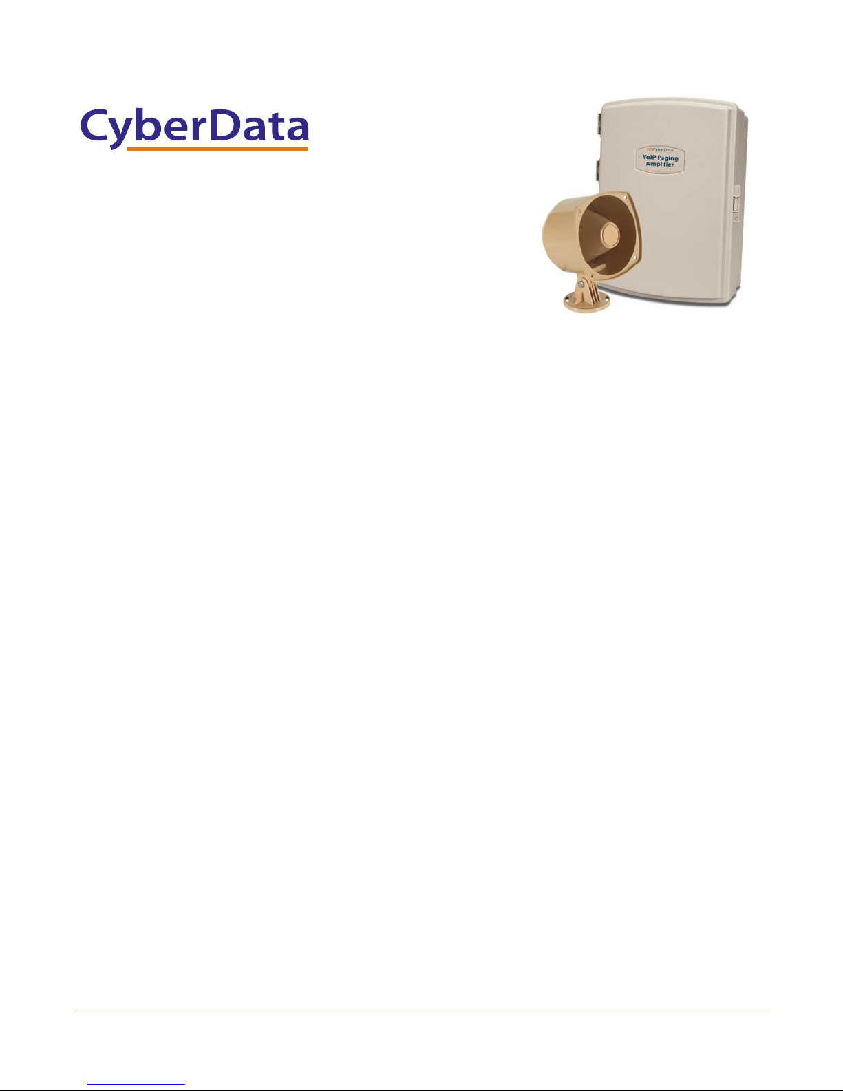
VoIP V2 Loudspeaker
Amplifier (Wireless)
Operations Guide
Part #011096
Document Part #930361G
for Firmware Version 6.0.2
CyberData Corporation
3 Justin Court
Monterey, CA 93940
(831) 373-2601
Page 2
VoIP V2 Paging Amplifier Operations Guide 930361G
Technical Support
The fastest way to get technical support for your VoIP product is to
submit a VoIP Technical Support form at the following website:
http://www.cyberdata.net/support/contactsupportvoip.html
We have several technical support staff monitoring this form and they will
contact you within 12 hours after receiving a submission.
Phone: (831) 373-2601, Ext. 333
Email: [email protected]
Fax: (831) 373-4193
Company and product information is at www.cyberdata.net.
The IP Endpoint Company
Part # 011096
COPYRIGHT NOTICE:
© 2011, CyberData Corporation, ALL RIGHTS RESERVED.
This manual and related materials are the copyrighted property of CyberData Corporation. No part
of this manual or related materials may be reproduced or transmitted, in any form or by any means
(except for internal use by licensed customers), without prior express written permission of
CyberData Corporation. This manual, and the products, software, firmware, and/or hardware
described in this manual are the property of CyberData Corporation, provided under the terms of
an agreement between CyberData Corporation and recipient of this manual, and their use is subject
to that agreement and its terms.
DISCLAIMER: Except as expressly and specifically stated in a written agreement executed by
CyberData Corporation, CyberData Corporation makes no representation or warranty, express or
implied, including any warranty or merchantability or fitness for any purpose, with respect to this
manual or the products, software, firmware, and/or hardware described herein, and CyberData
Corporation assumes no liability for damages or claims resulting from any use of this manual or
such products, software, firmware, and/or hardware. CyberData Corporation reserves the right to
make changes, without notice, to this manual and to any such product, software, firmware, and/or
hardware.
OPEN SOURCE STATEMENT: Certain software components included in CyberData products are
subject to the GNU General Public License (GPL) and Lesser GNU General Public License (LGPL)
“open source” or “free software” licenses. Some of this Open Source Software may be owned by
third parties. Open Source Software is not subject to the terms and conditions of the CyberData
COPYRIGHT NOTICE or software licenses. Your right to copy, modify, and distribute any Open
Source Software is determined by the terms of the GPL, LGPL, or third party, according to who
licenses that software.
Software or firmware developed by CyberData that is unrelated to Open Source Software is
copyrighted by CyberData, subject to the terms of CyberData licenses, and may not be copied,
modified, reverse-engineered, or otherwise altered without explicit written permission from
CyberData Corporation.
TRADEMARK NOTICE: CyberData Corporation and the CyberData Corporation logos are
trademarks of CyberData Corporation. Other product names, trademarks, and service marks may
be the trademarks or registered trademarks of their respective owners.
Operations Guide 930361G CyberData Corporation
Page 3

Revision Information
Revision 930361G, released on August 12, 2011, corresponds to firmware version 6.0.2 and has the
following changes:
• Adds Section 2.2.3.1, "Using the Amplified Outputs".
•Updates Figure 2-5, "Using the Amplified Outputs—Low Power Mode".
• Adds Figure 2-6, "Using the Amplified Outputs—High Power Mode".
Operations Guide 930361G CyberData Corporation
Page 4
Important Safety Instructions
GENERAL ALERT
GENERAL ALERT
1. Read these instructions.
2. Keep these instructions.
3. Heed all warnings.
4. Follow all instructions.
5. Do not use this apparatus near water.
6. Clean only with dry cloth.
7. Do not block any ventilation openings. Install in accordance with the manufacturer’s
instructions.
8. Do not install near any heat sources such as radiators, heat registers, stoves, or other apparatus
(including amplifiers) that produce heat.
9. Do not defeat the safety purpose of the polarized or grounding-type plug. A polarized plug has
two blades with one wider than the other. A grounding type plug has two blades and a third
grounding prong. The wide blade or the third prong are provided for your safety. If the
provided plug does not fit into your outlet, consult an electrician for replacement of the obsolete
outlet.
10. Protect the power cord from being walked on or pinched particularly at plugs, convenience
receptacles, and the point where they exit from the apparatus.
11. Only use attachments/accessories specified by the manufacturer.
12. Refer all servicing to qualified service personnel. Servicing is required when the apparatus has
been damaged in any way, such as power-supply cord or plug is damaged, liquid has been
spilled or objects have fallen into the apparatus, the apparatus has been exposed to rain or
moisture, does not operate normally, or has been dropped.
13. Prior to installation, consult local building and electrical code requirements.
Warning
Electrical H azard: This product should be installed by a lice nsed electric ian
according to al l local electrical and building codes.
Warning
Electrical H azard: To prevent injury, this appara tus must be securely attached to
the floor/wall in accordance with the installation instructions.
Operations Guide 930361G CyberData Corporation
Page 5
Pictorial Alert Icons
GENERAL ALERT
Hazard Levels
Danger: Indicates an imminently hazardous situation which, if not avoided, will result in death or
serious injury. This is limited to the most extreme situations.
Warning: Indicates a potentially hazardous situation which, if not avoided, could result in death or
serious injury.
General Alert
This pictoral alert indicates a potentially hazardous situation. This alert will be
followed by a haza rd level heading and more s pecific information about the
hazard.
Ground
This pictora l alert indicates the Earth grounding connection point.
Caution: Indicates a potentially hazardous situation which, if not avoided, could result in minor or
moderate injury. It may also alert users against unsafe practices.
Notice: Indicates a statement of company policy (that is, a safety policy or protection of property).
The safety guidelines for the equipment in this manual do not purport to address all the safety
issues of the equipment. It is the responsibility of the user to establish appropriate safety, ergonomic,
and health practices and determine the applicability of regulatory limitations prior to use. Potential
safety hazards are identified in this manual through the use of words Danger, Warning, and
Caution, the specific hazard type, and pictorial alert icons.
Operations Guide 930361G CyberData Corporation
Page 6

Abbreviations and Terms
Abbreviation or Term Definition
A-law A standard companding algorithm, used in European digital
communications systems to optimize, i.e., modify, the dynamic range of an
analog signal for digitizing.
AVP Audio Video Profile
Cat 5 TIA/EIA-568-B Category 5
DHCP Dynamic Host Configuration Protocol
LAN Local Area Network
LED Light Emitting Diode
Mbps Megabits per Second.
NTP Network Time Protocol
PBX Private Branch Exchange
PoE Power over Ethernet (as per IEEE 802.3af standard)
RTFM Reset Test Function Management
SIP Session Initiated Protocol
u-law A companding algorithm, primarily used in the digital telecommunication
UC Unified Communications
VoIP Voice over Internet Protocol
Operations Guide 930361G CyberData Corporation
Page 7

Contents
Chapter 1 Product Overview 1
1.1 How to Identify This Product ..............................................................................................................1
1.2 Typical System Installation ...................................................................................................................2
1.3 Product Features .....................................................................................................................................2
1.4 Supported Protocols ..............................................................................................................................3
1.5 Supported SIP Servers ...........................................................................................................................3
1.6 Product Specifications ...........................................................................................................................4
Chapter 2 Installing the VoIP V2 Loudspeaker Amplifier 5
2.1 Parts List .................................................................................................................................................. 5
2.2 Loudspeaker Amplifier Setup ..............................................................................................................6
2.3 Configure the Loudspeaker Amplifier Parameters .........................................................................18
i
2.2.1 Loudspeaker Amplifier Components ......................................................................................7
2.2.2 Loudspeaker Amplifier NEMA Box Components .................................................................8
2.2.3 Connecting the Loudspeaker Amplifier .................................................................................9
2.2.4 Loudspeaker Amplifier DIP Switches ...................................................................................11
2.2.5 VoIP V2 Loudspeaker Amplifier System Installation and Connection Options ..............12
2.2.6 Confirm Operation ....................................................................................................................15
2.2.7 Confirm the IP Address and Test the Audio .........................................................................16
2.2.8 Adjust the Volume ....................................................................................................................16
2.3.1 Loudspeaker Amplifier Web Page Navigation .....................................................................19
2.3.2 Log in to the Configuration Home Page ................................................................................20
2.3.3 Configure the Device Parameters ...........................................................................................23
2.3.4 Configure the Network Parameters ...................................................................................... 26
2.3.5 Configure the SIP Parameters .................................................................................................28
2.3.6 Configure the Night Ringer Parameters ................................................................................30
2.3.7 Configure the Sensor Configuration Parameters .................................................................32
2.3.8 Configure the Multicast Configuration Parameters ............................................................34
2.3.9 Configure the Audio Parameters ............................................................................................38
2.3.10 User-created Audio Files ........................................................................................................43
2.3.11 Configure the Event Parameters ...........................................................................................45
2.3.12 Configure the Autoprovisioning Parameters ......................................................................50
2.3.13 Upgrade the Firmware and Reboot the Loudspeaker Amplifier .....................................55
2.3.14 Reboot the Loudspeaker Amplifier ......................................................................................58
Appendix A Mounting the Amplifier 59
A.1 Mount the Amplifier .........................................................................................................................59
Appendix B Setting up a TFTP Server 61
B.1 Set up a TFTP Server ...........................................................................................................................61
B.1.1 In a LINUX Environment ........................................................................................................61
B.1.2 In a Windows Environment ...................................................................................................61
Appendix C Troubleshooting/Technical Support 62
C.1 Frequently Asked Questions (FAQ) ................................................................................................. 62
C.2 Documentation ....................................................................................................................................62
C.3 Contact Information ............................................................................................................................ 63
C.4 Warranty ...............................................................................................................................................64
C.4.1 Warranty & RMA Returns within the United States ...........................................................64
C.4.2 Warranty & RMA Returns Outside of the United States ....................................................64
C.4.3 Spare in the Air Policy .............................................................................................................64
C.4.4 Return and Restocking Policy ................................................................................................65
C.4.5 Warranty and RMA Returns Page ......................................................................................... 65
Index 66
Operations Guide 930361G CyberData Corporation
Page 8
1 Product Overview
AMPLIFIER,V2 VoIP LOUDSPEAKER,
WIRELESS, RoHS COMPLIANT
011096A / 021047E
Model number
WWW.CYBERDATA.NET
096000001
The CyberData SIP-enabled VoIP V2 Loudspeaker Amplifier (Wireless) provides an easy method for
implementing an IP-based overhead paging system for both new and legacy installations.
With up to 25 watts of driving power (802.3at), the Amplifier provides direct drive of a standard
Horn speaker and supports a line-out connector for connection to an external amplifier. The
interface is compatible with most SIP-based IP PBX servers that comply with the SIP RFC 3261. For
non-SIP environments, the Loudspeaker Amplifier can be configured to listen to multicast address
and port number combinations to form paging zones.
1.1 How to Identify This Product
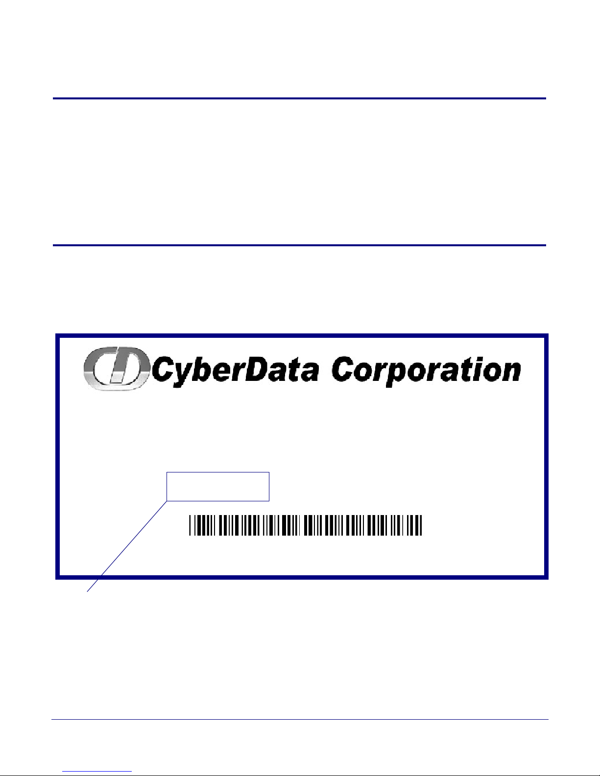
To identify the VoIP V2 Loudspeaker Amplifier (Wireless), look for a model number label similar to
the one shown in
Figure 1-1. The model number on the label should be 011096.
Figure 1-1. Model Number Label
1
Operations Guide 930361G CyberData Corporation
Page 9
1.2 Typical System Installation
802.3af Compliant Ethernet Switch
VoIP Phone SIP Server
12 34 56
Loudspeaker Amplifier
High Power PoE Injector in Box
• SIP (RFC 3261) compatible
• Dual-speed ethernet 10/100 Mbps
• Web-based configuration
• Web-based firmware upgradeable
• PoE 802.3at and 802.3af-enabled
•IGMP
• Line-out connector
• DTMF controlled relay with open sense
• Direct speaker drive
• User-uploadable tones
• Simultaneous SIP and Multicast
• Autoprovisioning
•Line-In capability
• Nightringer
• Weather-resistant NEMA enclosure
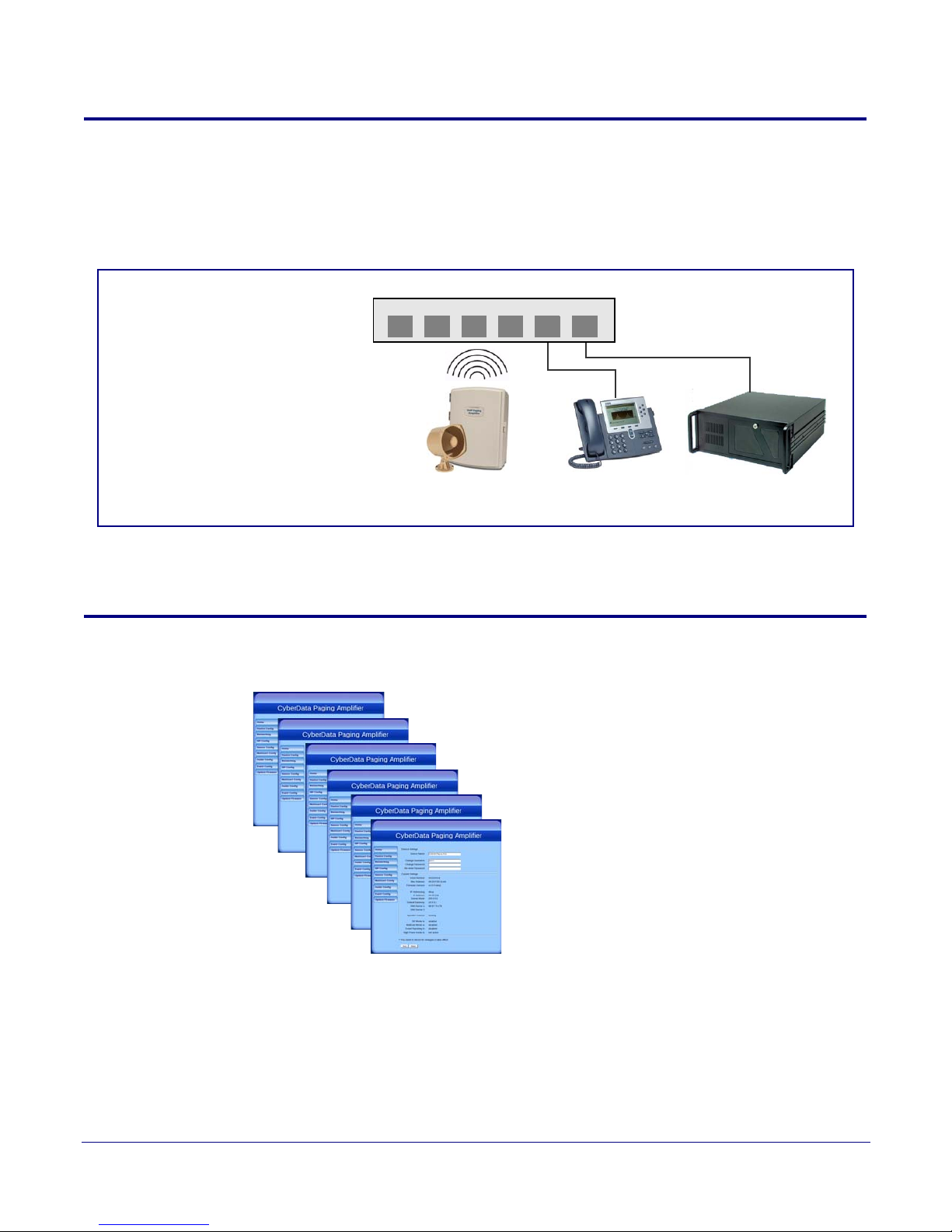
Figure 1-2 illustrates how the VoIP V2 Loudspeaker Amplifier is normally installed as part of a
public address system.
Figure 1-2. Typical Installation
Product Overview
Typical System Installation
2
1.3 Product Features
Operations Guide 930361G CyberData Corporation
Page 10

1.4 Supported Protocols
The Loudspeaker Amplifier supports:
•SIP
•Multicast
• HTTP Web-based configuration
Provides an intuitive user interface for easy system configuration and verification of
Loudspeaker Amplifier operations.
•DHCP Client
Dynamically assigns IP addresses in addition to the option to use static addressing.
•TFTP Client
Facilitates Web-based firmware upgrades of the latest Loudspeaker Amplifier capabilities.
•RTP
• RTP/AVP - Audio Video Profile
•SPEEX
• Audio Encodings
PCMU (G.711 mu-law)
PCMA (G.711 A-law)
Packet Time 20 ms
Product Overview
Supported Protocols
3
1.5 Supported SIP Servers
The following link contains information on how to configure the Loudspeaker Amplifier for the
supported SIP servers:
http://www.cyberdata.net/support/server/index.html
Operations Guide 930361G CyberData Corporation
Page 11

1.6 Product Specifications
Table 1. Product Specifications
Category Specification
Ethernet I/F 10/100 Mbps
Power Input PoE 802.3at or 802.3af
Operating Temperature -30 to 55 C (-22 to 131 F)
Protocol SIP RFC 3261
Payload Types G711, SPEEX
Regulatory Compliance FCC Class A, CE
Warranty 2 Years Limited
Dimensions 14” x 10” x 4”
Audio Output 802.3af - up to 10 Watts (default, 50% duty
cycle [one second on and one second off]).
802.3at - up to 22 Watts (default, 50% duty
cycle [one second on and one second off])
Product Overview
Product Specifications
4
Line In:
Input Signal Amplitudes
Input Impedance
Line Out:
Output Signal Amplitudes
Output Level
Total Harmonic Distortion
Output Impedance
Par t Nu mber 011096
2.0 VPP maximum
10k Ohm
2.0 VPP maximum
+2dBm nominal
0.5% maximum
10k Ohm
Operations Guide 930361G CyberData Corporation
Page 12
2 Installing the VoIP V2 Loudspeaker
Amplifier
2.1 Parts List
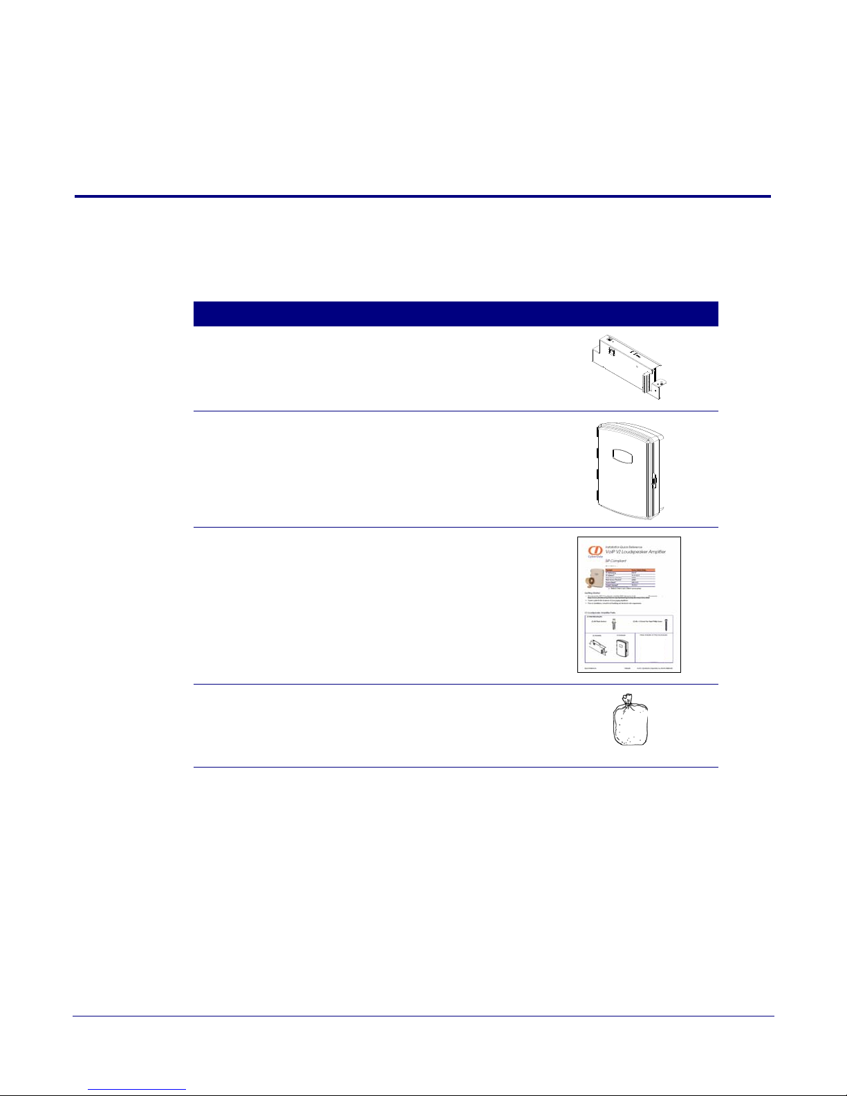
Ta bl e 2-1 illustrates the parts for each Loudspeaker Amplifier and includes a kit for mounting.
Table 2-1. Parts List
Quantity Part Name Illustration
1 Loudspeaker Amplifier Assembly
1 Enclosure
5
1 Installation Quick Reference Guide
1 Loudspeaker Amplifier Mounting Accessory Kit,
RoHS (part #071057A) which includes:
(3)Plastic Ribbed Anchors
(3) #6 Sheet Metal Screws
Operations Guide 930361G CyberData Corporation
Page 13

2.2 Loudspeaker Amplifier Setup
Set up and configure each Loudspeaker Amplifier before you mount it.
CyberData delivers each Loudspeaker Amplifier with the factory default values indicated in
Table 2-2:
Table 2-2. Factory Default Settings—Default of Netw ork
Parameter Factory Default Setting
IP Addressing DHCP
IP Address
Web Access Username admin
Web Access Password admin
Subnet Mask
Default Gateway
a
a
a
a. Default if there is not a DHCP server present.
Installing the VoIP V2 Loudspeaker Amplifier
10.10.10.10
255.0.0.0
10.0.0.1
6
Loudspeaker Amplifier Setup
Operations Guide 930361G CyberData Corporation
Page 14
2.2.1 Loudspeaker Amplifier Components
DIP Switches
Speaker Volume
Network Link LED (GREEN/YELLOW)
Status LED (GREEN)
A steady LED confirms that the Loudspeaker Amplifier is operational. The LED will blink during a page when it is online.
Network Activity LED (GREEN)
Power LED (GREEN/BLUE)
The power LED is a steady green in low power mode and
a steady blue during high power mode. The power LED
will only blink either during a boot up or a phone call.
RTFM Switch
To broadcast a Loudspeaker Amplifier’s current IP
address, press and hold the RTFM switch for a couple of
seconds and then release it.
To restore the factory defaults, complete the following
steps:
1. Press and hold the RTFM switch until you hear the
Loudspeaker Amplifier announce the words, “restoring
defaults” and “rebooting”.
2. Release the RTFM switch. The Loudspeaker Amplifier
will be restored to the factory default settings.
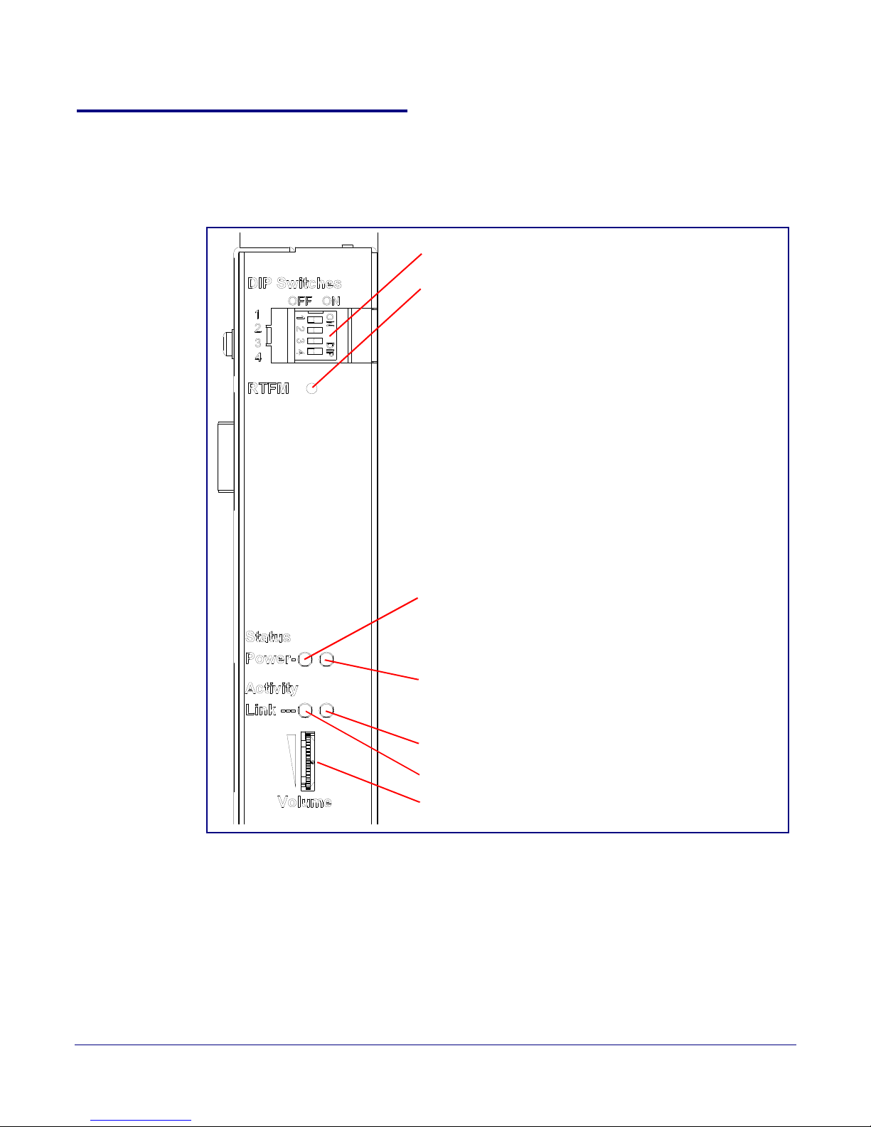
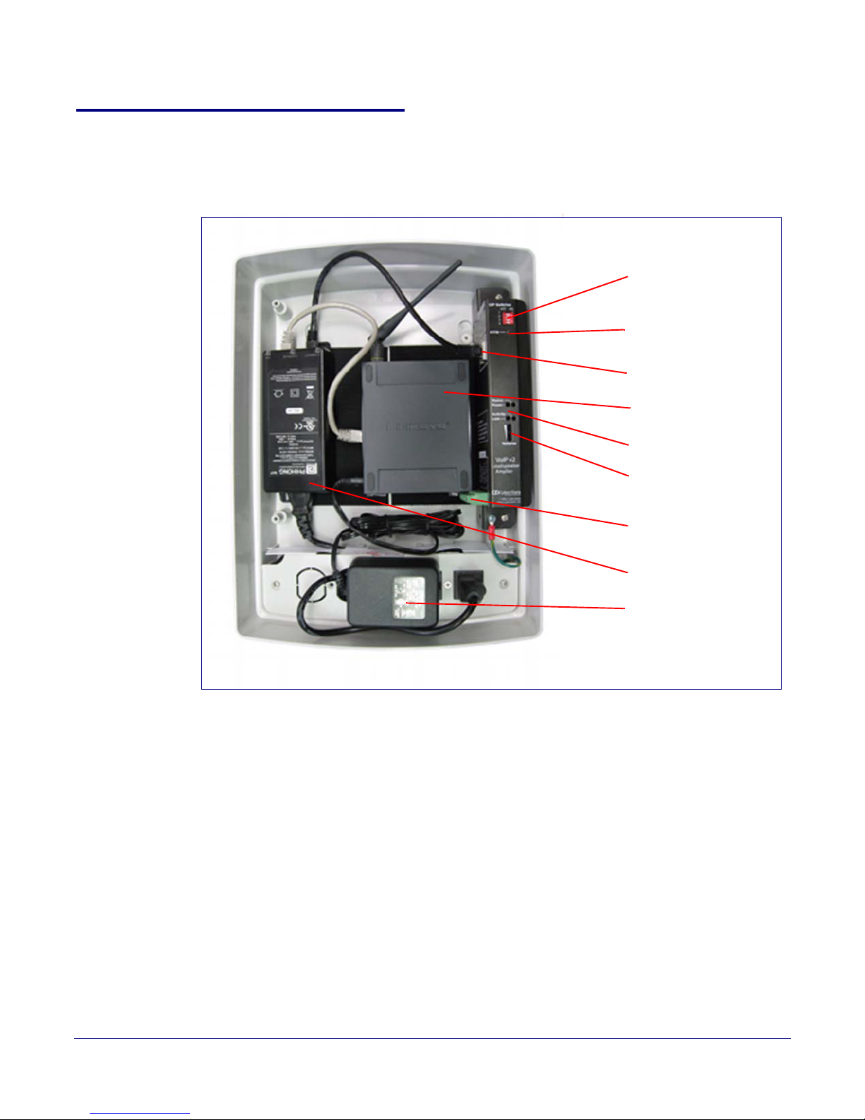
Figure 2-3 shows the components of the Loudspeaker Amplifier .
Figure 2-3. Loudspeaker Amplifier Components
Installing the VoIP V2 Loudspeaker Amplifier
Loudspeaker Amplifier Setup
7
Operations Guide 930361G CyberData Corporation
Page 15
Installing the VoIP V2 Loudspeaker Amplifier
Speaker Connection
Ethernet Connection
DIP Switches
RTFM Switch
Vol ume
AC power
Injector
LEDs
Non-PoE Ethernet Switch
2.2.2 Loudspeaker Amplifier NEMA Box Components
Figure 2-4 shows all of the NEMA box components of the loudspeaker amplifier.
Figure 2-4. Loudspeaker Amplifier Components—AC pow ered
8
Loudspeaker Amplifier Setup
Operations Guide 930361G CyberData Corporation
Page 16
2.2.3 Connecting the Loudspeaker Amplifier
AC Input*
~
+
Standard 1 Speaker Configuration
(802.3af mode)
8 Ohms
16 gauge wire
+
-
Use 16 gauge wire coming out of screw terminals.
Note
: The maximum wire length from the amplifier
to the speaker should not be more than 25 feet.
Non-PoE Ethernet Switch
*Note: This AC connection needs to
be installed by a certified electrician.
2.2.3.1 Using the Amplified Outputs
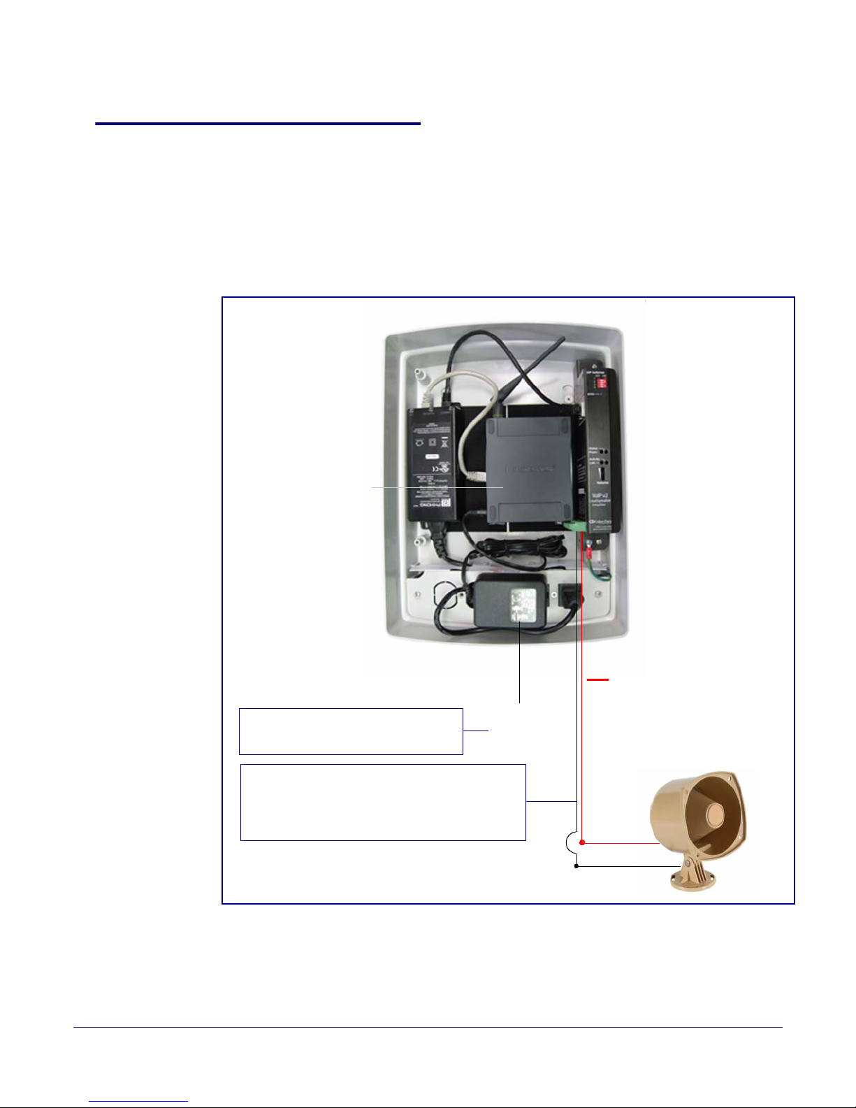
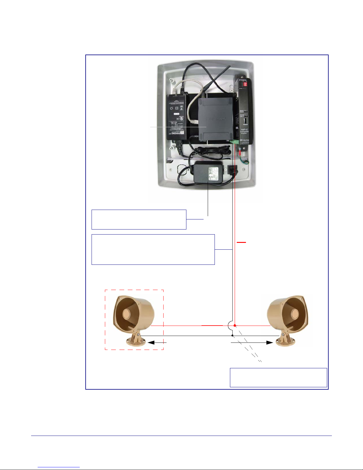
Figure 2-5 and Figure 2-6 illustrates how to connect the VoIP V2 Loudspeaker Amplifier and use the
amplified outputs in low and high power mode.
Installing the VoIP V2 Loudspeaker Amplifier
Loudspeaker Amplifier Setup
9
Low Power Mode
Figure 2-5. Using the Amplified O utputs—Low Power Mode
Operations Guide 930361G CyberData Corporation
Page 17
Installing the VoIP V2 Loudspeaker Amplifier
AC Input*
~
Non-PoE Ethernet Switch
2 speakers in parallel (4 Ohm total)
+
Note: Use wire nuts to connect wire
from the speakers to 16 gauge wire.
Twist wire nuts
Optional 2 Speaker Configuration
(802.3at mode)
8 Ohms
Standard 1 Speaker Configuration
(802.3af mode)
8 Ohms
16 gauge wire
25 feet maximum distance
++
--
Use 16 gauge wire coming out of screw terminals.
Note: Make sure that the wire length going to the
wire nuts is kept short (approximately 6 inches).
*Note: This AC connection needs to
be installed by a certified electrician.
Loudspeaker Amplifier Setup
10
High Power Mode
Figure 2-6. Using the Amplified Outputs—High Power Mode
Operations Guide 930361G CyberData Corporation
Page 18
2.2.4 Loudspeaker Amplifier DIP Switches
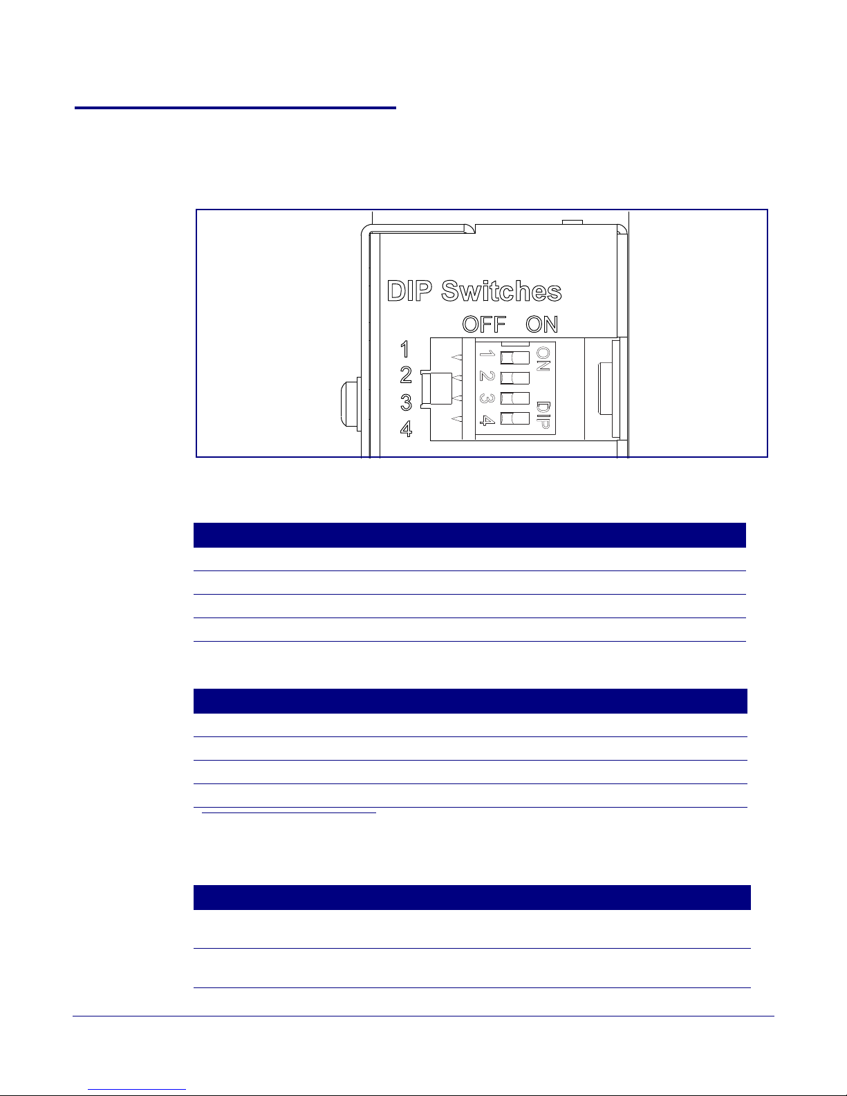
See Figure 2-7 to identify the DIP Switches.
Figure 2-7. DIP Switches
Installing the VoIP V2 Loudspeaker Amplifier
Loudspeaker Amplifier Setup
11
See Table 2-3 and Table 2-4 for the DIP Switch settings for the revision B (or later) board.
Table 2-3. DIP Switch Settings—Low Power—802.3af Compliant
DIP Switch Setting Description
1 OFF Sets PoE for 802.3af class.
2 N/A Not applicable for power setting.
3 ON Switch mode current set to LOW.
4 OFF Low gain amplifier setting.
Table 2-4. DIP Switch Settings—High Power—802.3at Compliant (Default)
a
DIP Switch Setting Description
1 ON Sets PoE for 802.3at class.
2 N/A Not applicable for power setting.
3 OFF Switch mode current set to HIGH.
4 ON Force high gain amplifier.
a. If set to high power, the unit will not power ON with 802.3af compliant switch. You must use a power injector
in this mode (CyberData part number 010867A).
Table 2-5. DIP Switch 2 Settings
DIP Switch Setting Description
2 OFF Manual Vol. The speaker volume is set manually by the analog volume
2 ON Bypass. Bypasses the manual volume control of the analog volume
Operations Guide 930361G CyberData Corporation
trimmer.
trimmer and uses the web page volume settings.
Page 19
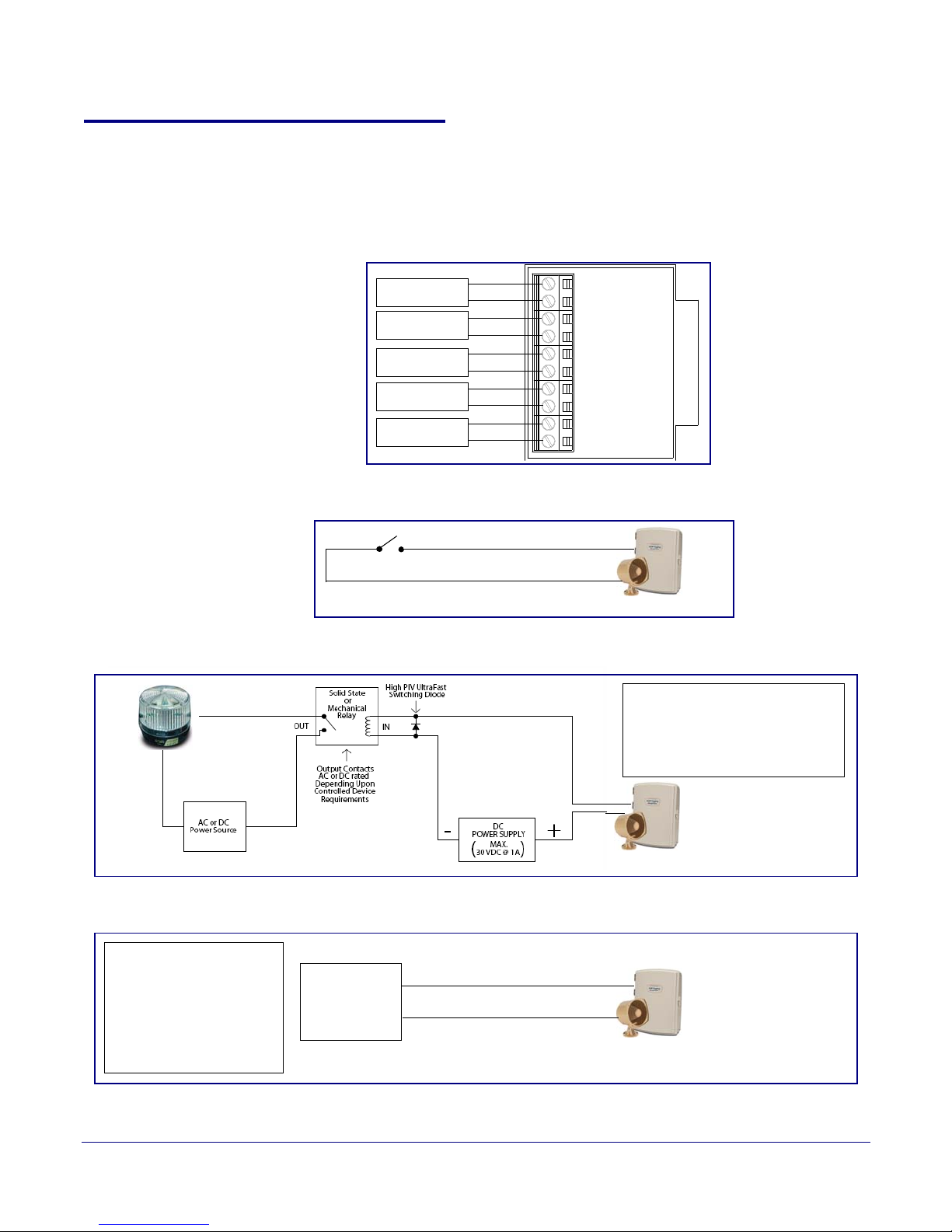
Installing the VoIP V2 Loudspeaker Amplifier
1-Sense (+)
2-GND
3-Relay COM
4-Relay NO
5-Line-In(+)
6-Line-In(-)
7-Line-Out(+)
8-Line-Out(-)
9-Spkr Out(+)
10-Spkr Out (-)
CLASS II WIRING
See Figure 2-9
See Figure 2-
See Figure 2-
See Figure 2-
See Figure 2-13
Amplifier
Amplifier
+12V Strobe
When the Loudspeaker Amplifier is
called from a remote phone, the
relay on the Loudspeaker Amplifier
can be programmed to blink and
drive an Alert Strobe.
Amplifier
When line-in is enabled on
the V2 Amplifier, the audio
received from the line-in
connection will be played
to the speaker(s) and lineout connection as the lowest priority audio.
Line Plug
Loudspeaker Amplifier Setup
2.2.5 VoIP V2 Loudspeaker Amplifier System Installation and Connection
Options
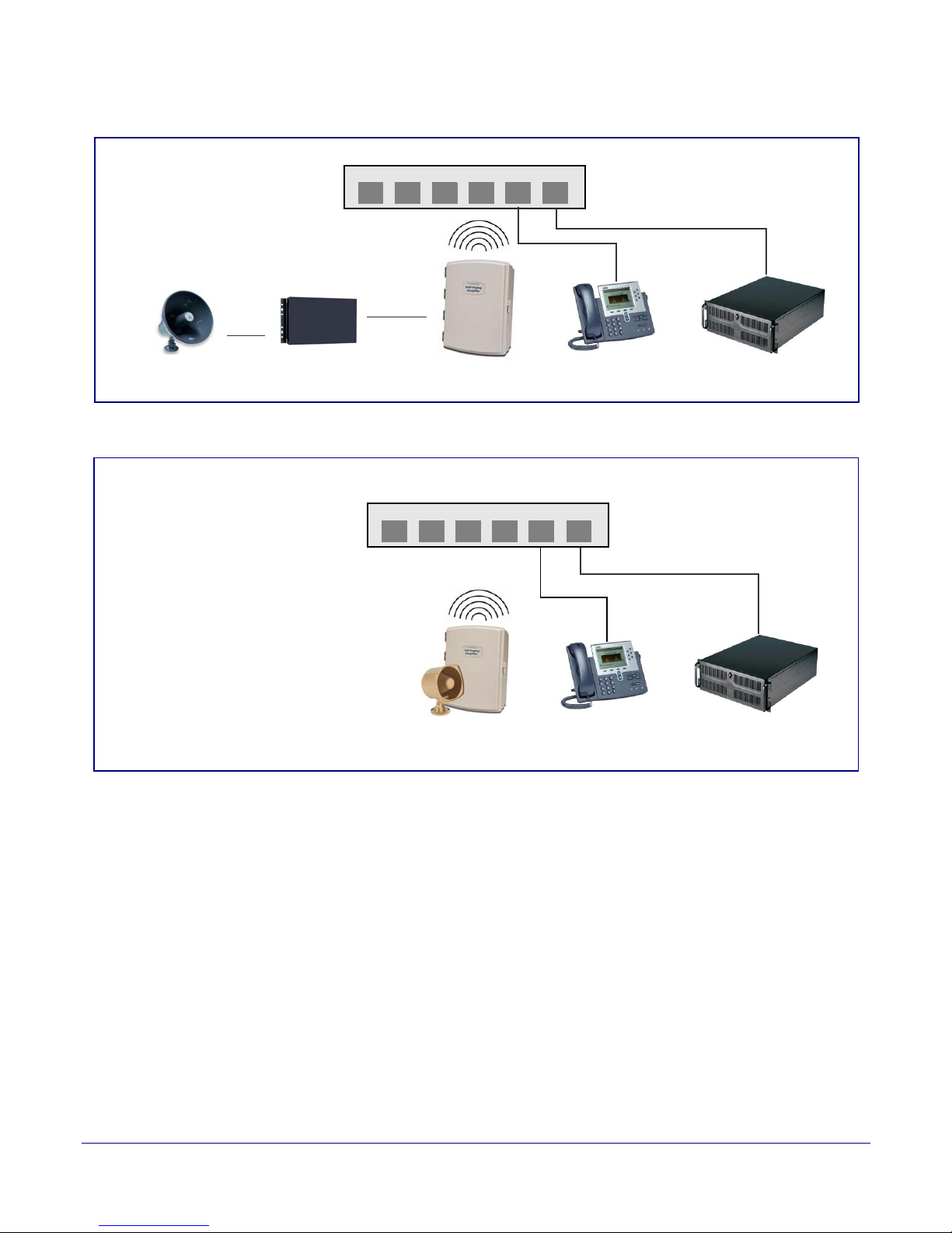
The following figures show the connection options for the VoIP V2 Loudspeaker Amplifier.
Figure 2-8. Loudspeaker Amplifier Connections
Figure 2-9. Sensor Connectio n
12
Operations Guide 930361G CyberData Corporation
Figure 2-10. Relay or Strobe Alert Connection
Figure 2-11. Line-In Connection
Page 20
Installing the VoIP V2 Loudspeaker Amplifier
Generic Ethernet Switch
IP Phone IP PBX Server
12 34 56
Existing Loudspeaker
Existing Amplifier
Line-out
Connection
(up to 25 watts)
Loudspeaker Amplifier
VoIP Phone
12 34 56
011068 Loudspeaker
IP PBX Server
802.3af Compliant Ethernet Switch
High Power PoE Switch
(up to 25 watts)
Loudspeaker Amplifier
High Power PoE Injector in Box
Figure 2-12. Line Out Connection
Figure 2-13. Speaker Out Connection
13
Loudspeaker Amplifier Setup
Operations Guide 930361G CyberData Corporation
Page 21
Installing the VoIP V2 Loudspeaker Amplifier
Loudspeaker Amplifier Setup
See Table 2-6 for details about the Loudspeaker Amplifier connections.
Table 2-6. Loudspeaker Amplifier Connections
Connection Connection Details Location
14
Ethernet
2.2.5.1 Loudspeaker Type
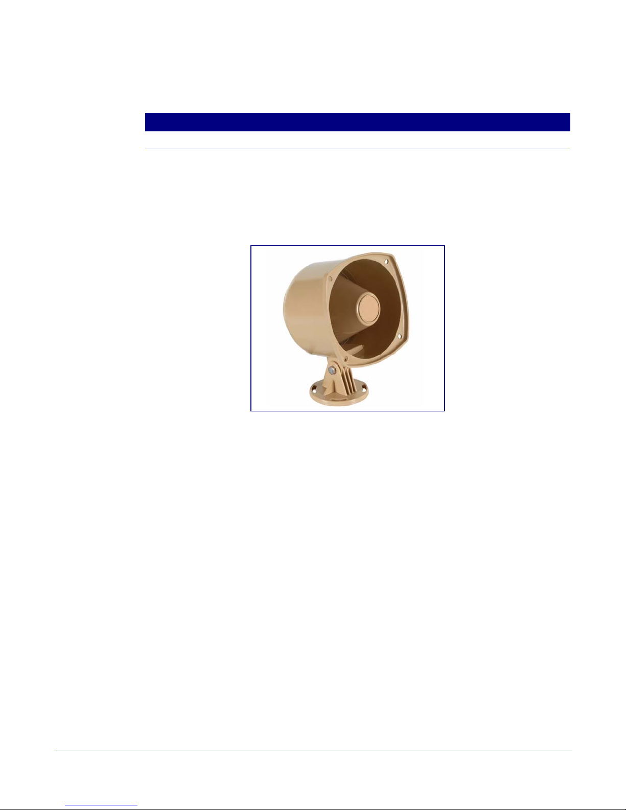
Using the amplified output, the CyberData VoIP V2 Loudspeaker Amplifier supports the 011068
Loudspeaker or equivalent unamplified loudspeaker.
● Use a RJ 45 cable.
Figure 2-14. 011068 Loudspeaker
VoIP V2 Loudspeaker Amplifier
2.2.5.2 Cabling/Wiring
Using the amplified output, you may connect a 011068 loudspeaker or equivalent unamplified
speaker to a Loudspeaker Amplifier with good quality speaker wire that is 16 gauge and limited to
25 feet in length.
Operations Guide 930361G CyberData Corporation
Page 22
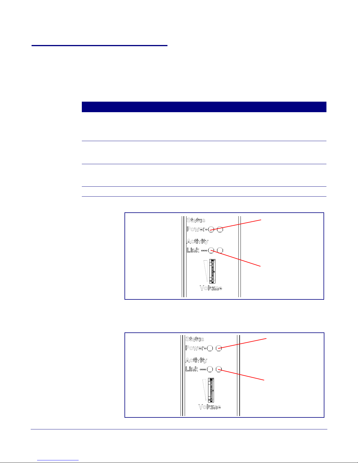
2.2.6 Confirm Operation
Power LED (blue/green)
Link LED (green/yellow)
Status LED (green)
Activity LED
(green)(yellow)
After connecting the Loudspeaker Amplifier to the 802.3af compliant ethernet hub, use the LEDs on
the Loudspeaker Amplifier face to confirm that the Loudspeaker Amplifier is operational and
linked to the network.
LED Color Function
Power Blue/Green The power LED is illuminated a steady green when the power is on and in
Status Green After supplying power to the Loudspeaker Amplifier, a steady LED confirms
Link Green/Ye l l ow The Link LED is illuminated green for a 10Mb link or yellow/green for a
Activity Green The Activity LED blinks to indicate network traffic.
Installing the VoIP V2 Loudspeaker Amplifier
Loudspeaker Amplifier Setup
Table 2-7. Loudspeaker Amplifier LEDs
low power mode. The power LED is illuminated a steady blue when the
amplifier is in high power mode. The power LED will blink during a boot up or
a phone call.
that the Loudspeaker Amplifier is operational. The status LED will blink
during a page when it is online.
100Mb link when the network link to the Loudspeaker Amplifier is
established.
15
Figure 2-15. Loudspeaker Amplifier LEDs—Power and Link
Figure 2-16. Loudspeaker Amplifier LEDs—Status and Activity
Operations Guide 930361G CyberData Corporation
Page 23
2.2.7 Confirm the IP Address and Test the Audio
RTFM switch
GENERAL ALERT
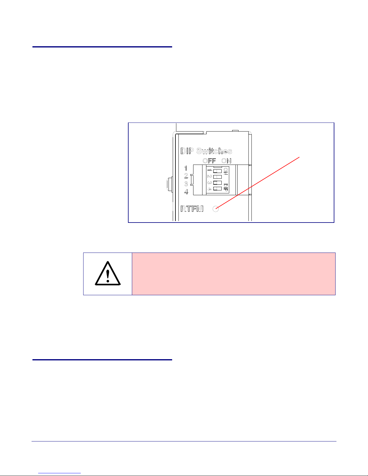
2.2.7.1 RTFM Switch
When the Loudspeaker Amplifier is operational and linked to the network, use the Reset Test
Function Management (RTFM) switch (
and confirm the Loudspeaker Amplifier’s IP Address and test the audio to verify that it is working.
Figure 2-17) on the Loudspeaker Amplifier face to announce
Figure 2-17. RTFM Switch
Installing the VoIP V2 Loudspeaker Amplifier
Loudspeaker Amplifier Setup
16
Announcing the IP
Address
Restoring the
Factory Default
Settings
To announce a Loudspeaker Amplifier’s current IP address:
● Press and hold the RTFM switch for a couple of seconds and then release it.
To restore the factory default settings, complete the following steps:
1. Press and hold the RTFM switch until you hear the Paging Amplifier announce the words,
“restoring defaults” and “rebooting”.
2. Release the RTFM switch. The Paging Amplifier will be restored to the factory default settings.
2.2.8 Adjust the Volume
There are two ways to adjust the volume for the Loudspeaker Amplifier:
•The Speaker Volume (0-9) setting on the Device Configuration page
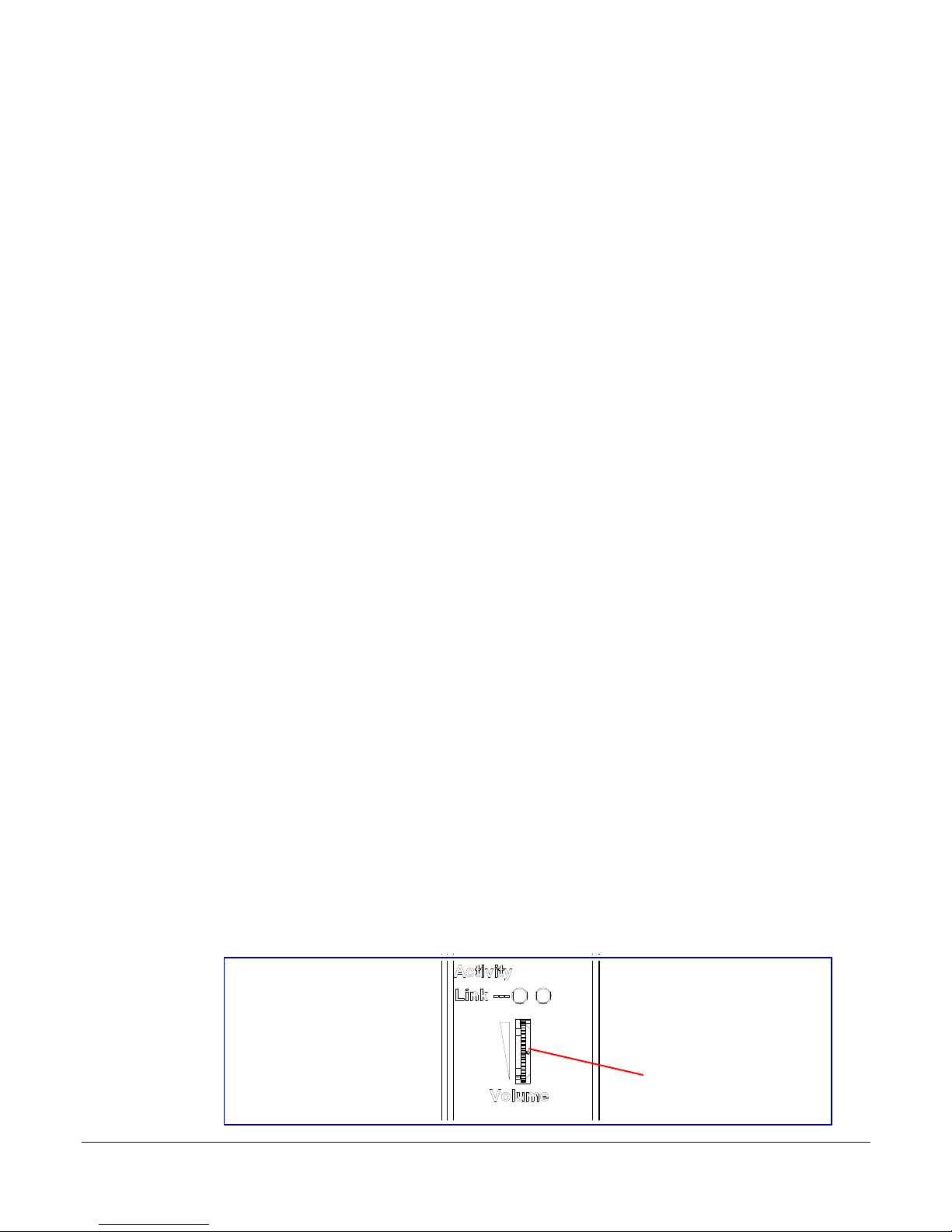
•The external Vo lu me dial on the Loudspeaker Amplifier face
Caution
Equipment Caution: Pressing and holding the RTFM switch for more than five
seconds will restore the V2 Paging Amplifier to the f ac tory default settings . See
the “
Restoring the Factory Default Sett ings” section.
Operations Guide 930361G CyberData Corporation
Page 24
2.2.8.1 The “Speaker Volume (0-9)” Setting
External volume dial
To adjust the Loudspeaker Amplifier volume with the Speaker Volume (0-9) setting on the Device
Configuration page, complete the following steps:
1. Make sure that dip switch 2 is set to ON.
2. Go to the Loudspeaker Amplifier Home page.
3. Select the Device Configuration page.
4. In the Speaker Volume (0-9) box, type a number between 0 (lowest) and 9 (highest).
5. Select Save.
6. Select Reboot.
2.2.8.2 The “Line-In Volume (0-9)” Setting
To adjust the Loudspeaker Amplifier volume with the Line-In Playback Volume (0-9) setting on the
Device Configuration page, complete the following steps:
Installing the VoIP V2 Loudspeaker Amplifier
Loudspeaker Amplifier Setup
17
1. Make sure that dip switch 2 is set to ON.
2. Go to the Loudspeaker Amplifier Home page.
3. Select the Device Configuration page.
4. In the Line-In Playback Volume (0-9) box, type a number between 0 (lowest) and 9 (highest).
5. Select Save.
6. Select Reboot.
2.2.8.3 External Volume Dial
To adjust the Loudspeaker Amplifier volume with the external volume dial, complete the following
steps:
1. Make sure that dip switch 2 is set to OFF.
2. Turn the external Vo lu me dial (Figure 2-18) on the Loudspeaker Amplifier face.
Note For the lineout volume, the volume is fixed and the volume control is adjusted through an
external amplifier.
Figure 2-18. External Volume Dial
Operations Guide 930361G CyberData Corporation
Page 25

Installing the VoIP V2 Loudspeaker Amplifier
Configure the Loudspeaker Amplifier Parameters
2.3 Configure the Loudspeaker Amplifier Parameters
To configure the Loudspeaker Amplifier online, use a standard web browser.
Configure each Loudspeaker Amplifier and verify its operation before you mount it. When you are
ready to mount a Loudspeaker Amplifier enclosure, refer to
instructions.
All Loudspeaker Amplifier are initially configured with the default IP settings
indicated in Table 2-8.
When configuring more than one Loudspeaker Amplifier, attach the Loudspeaker Amplifiers to the
network one at a time to avoid IP address conflicts.
Table 2-8. Factory Default Settings
Param et er Factory Default Setting
IP Addressing DHCP
IP Address
Web Access Username admin
a
10.10.10.10
Appendix A, "Mounting the Amplifier" for
18
Web Access Password admin
Subnet Mask
Default Gateway
a
a
255.0.0.0
10.0.0.1
a. Default if there is not a DHCP server present.
Operations Guide 930361G CyberData Corporation
Page 26
Configure the Loudspeaker Amplifier Parameters
2.3.1 Loudspeaker Amplifier Web Page Navigation
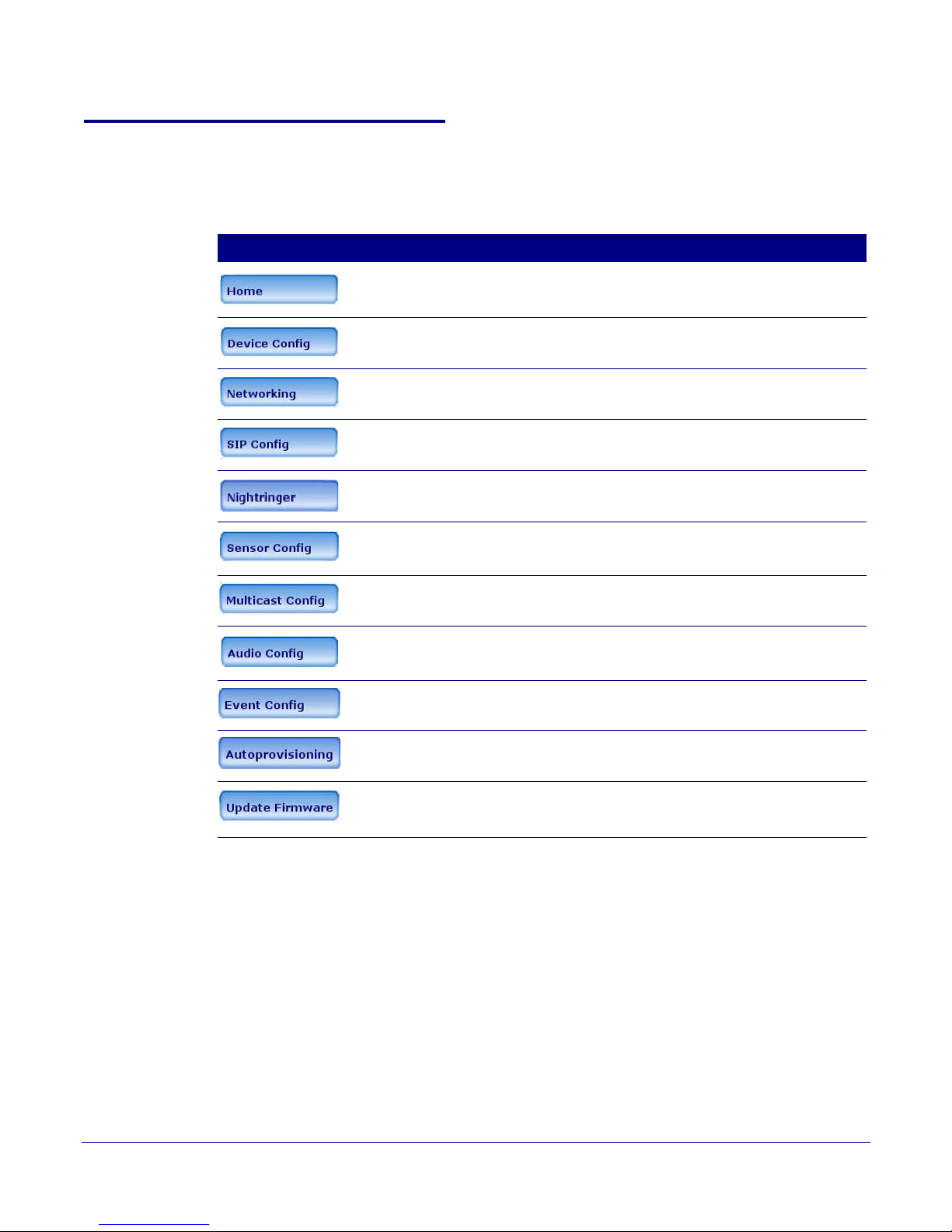
Ta bl e 2-9 shows the navigation buttons that you will see on every Loudspeaker Amplifier web page.
Table 2-9. Loudspeaker Amplifier Web Page Navigation
Web Page Item Description
Link to the Home page.
Link to the Device Configuration page.
Link to the Networking page.
Link to the SIP Configuration page.
Link to the Nightringer page.
Installing the VoIP V2 Loudspeaker Amplifier
19
Link to the Sensor Configuration page.
Link to the Multicast Configuration page.
Link to the Audio Configuration page.
Link to the Event Configuration page.
Link to the Autoprovisioning Configuration page.
Link to the Update Firmware page.
Operations Guide 930361G CyberData Corporation
Page 27

2.3.2 Log in to the Configuration Home Page
1. Open your browser to the Loudspeaker Amplifier IP address.
Note If the network does not have access to a DHCP server, the device will default to an IP
address of 10.10.10.10.
Note Make sure that the PC is on the same IP network as the Loudspeaker Amplifier.
Note You may also download CyberData’s VoIP Discovery Utility program which allows you to
easily find and configure the default web address of the CyberData VoIP products.
CyberData’s VoIP Discovery Utility program is available on the VoIP V2 Loudspeaker
Amplifier product page at:
http://www.cyberdata.net/support/voip/discovery_utility.html
The Loudspeaker Amplifier ships in DHCP mode. To get to the Home page, use the discovery
utility to scan for the device on the network and open your browser from there.
Installing the VoIP V2 Loudspeaker Amplifier
Configure the Loudspeaker Amplifier Parameters
20
Operations Guide 930361G CyberData Corporation
Page 28
Installing the VoIP V2 Loudspeaker Amplifier
Configure the Loudspeaker Amplifier Parameters
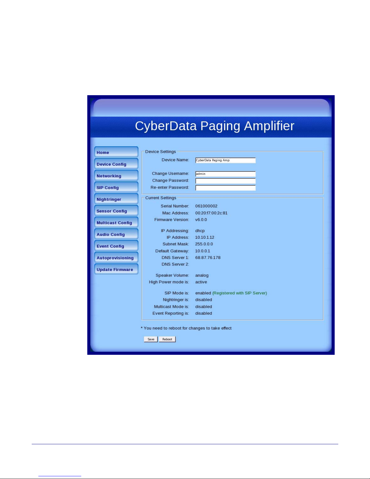
2. When prompted, use the following default Web Access Username and Web Acces s Password
to access the Home Page (
Figure 2-19):
Web Access Username: admin
Web Access Password: admin
Figure 2-19. Home Page
21
Operations Guide 930361G CyberData Corporation
Page 29
Installing the VoIP V2 Loudspeaker Amplifier
Configure the Loudspeaker Amplifier Parameters
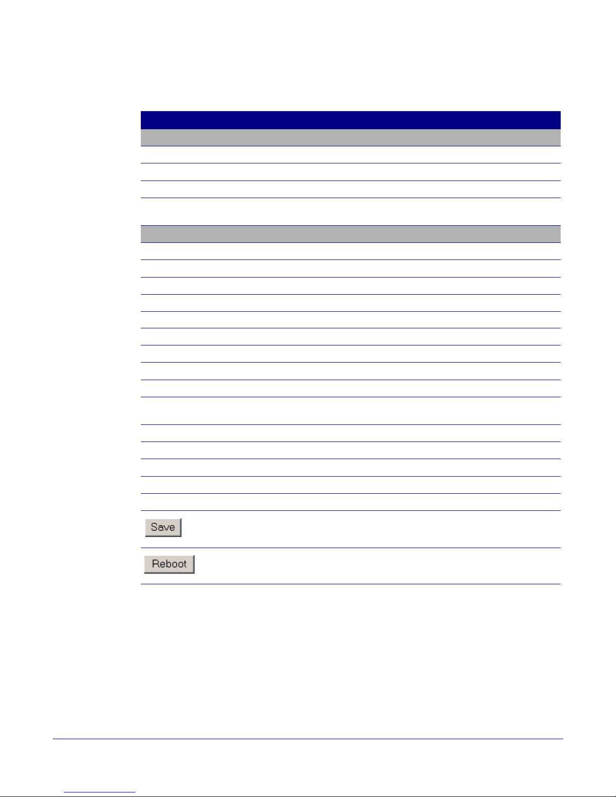
3. On the Home Page, review the setup details and navigation buttons described in Tabl e 2-10.
Table 2-10. Home Page Overview
Web Page Item Description
Device Settings
Device Name Shows the device name (25 character limit).
Change Username Type in this field to change the username (25 character limit).
Change Password Type in this field to change the password (19 character limit).
Re-enter Password Type the password again in this field to confirm the new password
(19 character limit).
Current Settings
Serial Number Shows the device serial number.
Mac Address Shows the device Mac address.
Firmware Version Shows the current firmware version.
IP Addressing Shows the current IP addressing setting (DHCP or Static).
IP Address Shows the current IP address.
22
Subnet Mask Shows the current subnet mask address.
Default Gateway Shows the current default gateway address.
DNS Server 1 Shows the current DNS Server 1 address.
DNS Server 2 Shows the current DNS Server 2 address.
Speaker Volume Shows the current Loudspeaker Amplifier volume mode:
Digital (web page) or Analog (volume knob).
High Power Mode is Shows the current status of High Power mode.
SIP Mode is Shows the current status of the SIP Mode.
Nightringer is Shows the current status of the Nightringer.
Multicast Mode is Shows the current status of the Multicast Mode.
Event Reporting is Shows the current status of the Event Reporting.
Click the Save button to save your configuration settings.
Note: You need to reboot for changes to take effect.
Click on the Reboot button to reboot the system.
Operations Guide 930361G CyberData Corporation
Page 30
2.3.3 Configure the Device Parameters
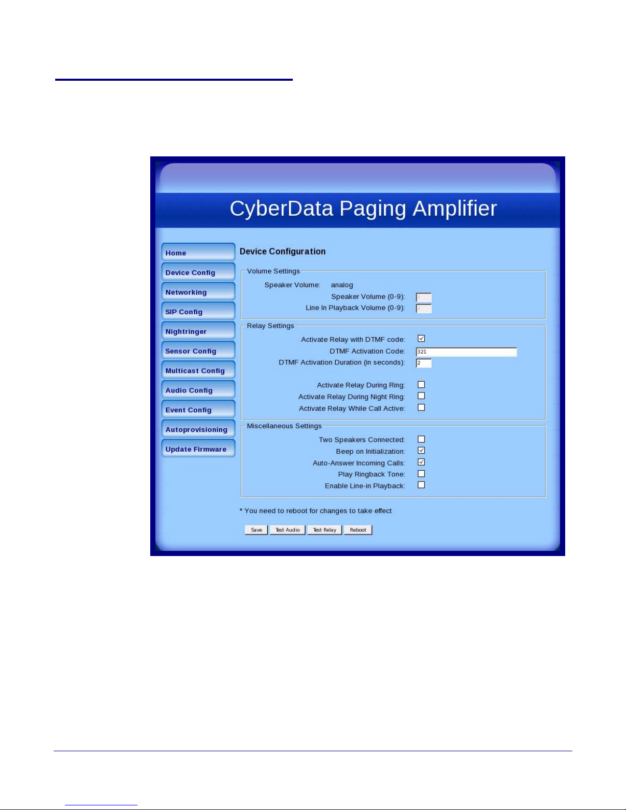
1. Click the Device Configuration button to open the Device Configuration page. See Figure 2-20.
Figure 2-20. Device Configuration Page
Installing the VoIP V2 Loudspeaker Amplifier
Configure the Loudspeaker Amplifier Parameters
23
Operations Guide 930361G CyberData Corporation
Page 31

Installing the VoIP V2 Loudspeaker Amplifier
Configure the Loudspeaker Amplifier Parameters
2. On the Device Configuration page, you may enter values for the parameters indicated in
Ta bl e 2-11.
Table 2-11. Device Configuration Parameters
Web Page Item Description
Volume Settings
Speaker Volume Shows the current speaker volume mode (Analog or Digital)
Speaker Volume (0-9) Type the desired Loudspeaker Amplifier volume level into this field
(range is 0 - 9).
Line-In Playback Volume (0-9) Type the desired line-in playback volume level into this field
(range is 0 - 9).
Relay Settings
Activate Relay with DTMF Code When selected, the relay can be activated with a DTMF code.
DTMF Activation Code Type the desired DTMF activation code (25 character limit).
DTMF Activation Duration
(in seconds)
Type the desired DTMF activation duration (in seconds)
(1 character limit).
Activate Relay During Ring When selected, the relay will be activated for as long as the phone is
ringing.
NOTE: When the phone is set to Auto Answer, it will not ring and this
option does nothing.
24
Activate Relay During Night
Ring
When selected, the relay will be activated for as long as a night ring
tone is playing.
NOTE: When the phone is set to Auto Answer, it will not ring and this
option does nothing.
Activate Relay While Call Active When selected, the relay will be activated for as long as the call is
active.
Miscellaneous Settings
Two Speakers Connected Select this option if two speakers are connected to the Loudspeaker
Amplifier.
Beep on Initialization When selected, you will hear a beep when the Loudspeaker Amplifier
initializes.
Auto-Answer Incoming Calls When selected, the Loudspeaker Amplifier automatically answers
incoming calls.
Play Ringback Tone Check this box to enable the device to play a ringtone while the remote
device is ringing.
Enable Line In Playback When selected, whatever audio source that you have selected (mp3
player, internet stream, etc.) will be played.
Note: The line in audio will be treated as low priority audio that will only
play if there is no other audio playing. When higher priority audio is
playing, the line in audio will be muted.
Click the Save button to save your configuration settings.
Note: You need to reboot for changes to take effect.
Operations Guide 930361G CyberData Corporation
Page 32
Configure the Loudspeaker Amplifier Parameters
Table 2-11. Device Configuration Parameters (continued)
Web Page Item Description
Click on the Test Audio button to do an audio test. Generates a voice
message for testing the device audio quality and volume. It plays the
audio at the volume you have configured the paging amp for
Note: If the test audio button is pressed while music is playing via the
Enabled Line In feature, the music will be muted during the test audio
message.
Click on the Test Relay button to do a relay test.
Click on the Reboot button to reboot the system.
3. After changing the parameters, click the Save button.
Installing the VoIP V2 Loudspeaker Amplifier
25
Operations Guide 930361G CyberData Corporation
Page 33
2.3.4 Configure the Network Parameters
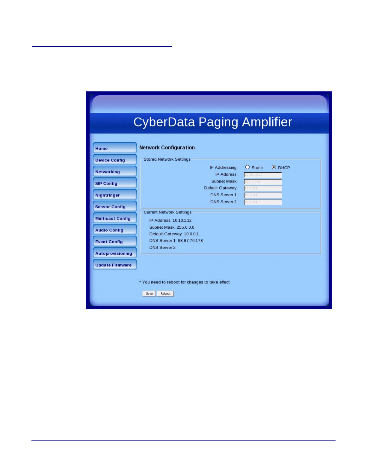
1. Click the Networking button to open the Network Configuration page (Figure 2-21).
Figure 2-21. Network Configuration Page
Installing the VoIP V2 Loudspeaker Amplifier
Configure the Loudspeaker Amplifier Parameters
26
Operations Guide 930361G CyberData Corporation
Page 34
Installing the VoIP V2 Loudspeaker Amplifier
Configure the Loudspeaker Amplifier Parameters
2. On the Network Configuration page, enter values for the parameters indicated in Tab le 2-12.
Table 2-12. Network Configuration Parameters
Web Page Item Description
Stored Network Settings
IP Addressing* Select either DHCP IP Addressing or Static IP Addressing by
marking the appropriate radio button. If you select Static, configure
the remaining parameters indicated in
Table 2-12. If you select
DHCP, go to Step 3.
IP Address* Enter the Static IP address.
Subnet Mask Enter the Subnet Mask address.
Default Gateway Enter the Default Gateway address.
DNS Server 1* Enter the DNS Server 1 address.
DNS Server 2* Enter the DNS Server 2 address.
Current Network Settings Shows the current network settings.
IP Address Shows the current Static IP address.
Subnet Mask Shows the current Subnet Mask address.
27
Default Gateway Shows the current Default Gateway address.
DNS Server 1 Shows the current DNS Server 1 address.
DNS Server 2 Shows the current DNS Server 2 address.
Click the Save button to save your configuration settings.
Note: You need to reboot for changes to take effect.
Click on the Reboot button to reboot the system.
3. After changing the parameters, click Save Settings. This updates the changed parameters and
reboots the Loudspeaker Amplifier if appropriate.
4. Connect the Loudspeaker Amplifier to the target network.
5. From a system on the same network as the Loudspeaker Amplifier, open a browser with the
new IP address of the Loudspeaker Amplifier.
Operations Guide 930361G CyberData Corporation
Page 35
2.3.5 Configure the SIP Parameters
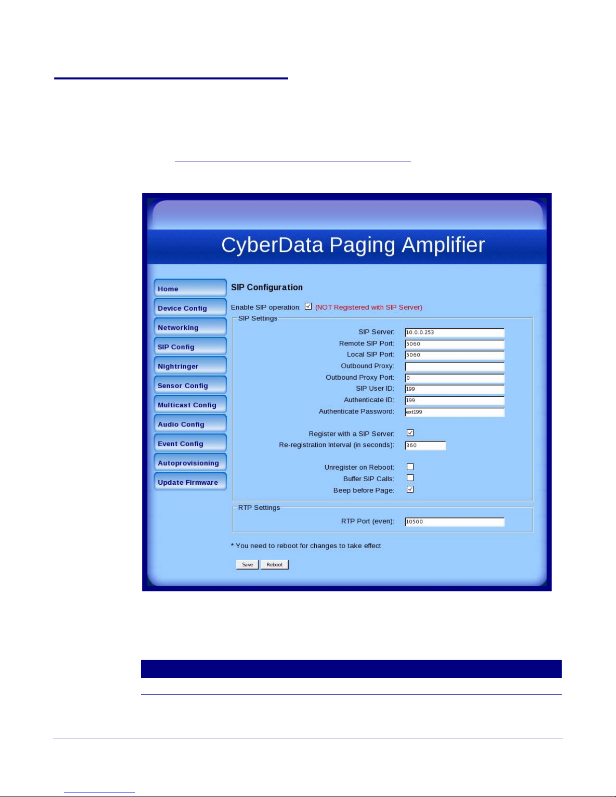
1. Click SIP Config to open the SIP Configuration page (Figure 2-22).
Note For specific server configurations, go to the IP-PBX Server Compatibility page at:
http://www.cyberdata.net/support/server/index.html
Figure 2-22. SIP Configuratio n Page
Installing the VoIP V2 Loudspeaker Amplifier
Configure the Loudspeaker Amplifier Parameters
28
2. On the SIP Configuration page, you may enter values for the parameters
indicated in Ta b le 2-13.
Web Page Item Description
Enable SIP Operation Enables or disables SIP operation.
Operations Guide 930361G CyberData Corporation
Table 2-13. SIP Configuration Parameters
Page 36

Installing the VoIP V2 Loudspeaker Amplifier
Configure the Loudspeaker Amplifier Parameters
Table 2-13. SIP Configuration Parameters (continued)
Web Page Item Description
SIP Settings
SIP Server* Type the SIP server represented as either a numeric IP address in dotted
decimal notation or the fully qualified host name (64 character limit
[FQDN]).
Remote SIP Port* Type the Remote SIP Port number (default 5060)
(0 - 65535).
Local SIP Port* Type the Local SIP Port number (default 5060)
(0 - 65535).
Outbound Proxy Type the Outbound Proxy as either a numeric IP address in dotted decimal
notation or the fully qualified host name
(64 character limit [FQDN]).
Outbound Proxy Port Type the Outbound Proxy Port number (0 - 65535).
SIP User ID* Type the SIP User ID (up to 25 alphanumeric characters).
Authenticate ID* Type the Authenticate ID
(up to 25 alphanumeric characters).
Authenticate Password* Type the Authenticate Password (up to 25 alphanumeric characters).
Register with a SIP Server* Enable or disable SIP Registration.
29
Re-registration Interval
(in seconds)*
Type the SIP Registration lease time in seconds
(default is 120 seconds) (range is 100 - ?).
Unregister on Reboot* • When selected, the Loudspeaker Amplifier automatically unregisters
when it is rebooted.
• When not selected, the Loudspeaker Amplifier remains registered when it
is rebooted.
Buffer SIP Calls When this is enabled, SIP calls to the speaker will be stored in memory and
will play when either the call is terminated or the buffer is full. The receive
buffer is 2MB in size and this is equal to about four minutes of ulaw
encoded audio.
Beep Before Page Enable/Disable the tone (beep) before each page.
RTP Settings
RTP Port (even) Specify the port number used for the RTP stream after establishing a SIP
call. The RTP port has to be an even number between 0 and 65534. This
port can be programmed for people who are not working on a local LAN,
but who want to have outside access. Instead of RTP port being a random
port, it will be set up so that only two ports can be opened in a firewall.
Note: The RTP port number has to be an even number because the control
port is always one port number higher. Therefore, audio will go through the
port number that you enter into the RTP port field, but the RTP control
signals will go through a port that is one number higher than the RTP port
field.
Click the Save button to save your configuration settings.
Note: You need to reboot for changes to take effect.
3. After changing the parameters, click Save to save the settings.
Operations Guide 930361G CyberData Corporation
Click on the Reboot button to reboot the system.
Page 37
2.3.6 Configure the Night Ringer Parameters
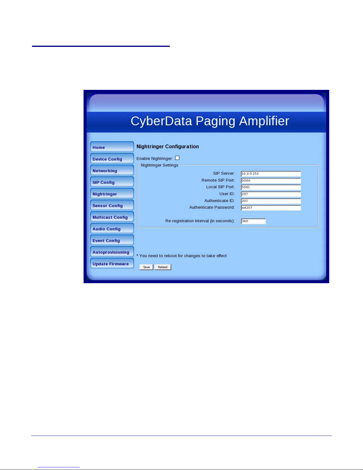
1. Click on the Nightringer button to open the Nightringer Configuration page. See Figure 2-25.
Figure 2-23. Nightringer Configuration Setup
Installing the VoIP V2 Loudspeaker Amplifier
Configure the Loudspeaker Amplifier Parameters
30
Operations Guide 930361G CyberData Corporation
Page 38
Installing the VoIP V2 Loudspeaker Amplifier
Configure the Loudspeaker Amplifier Parameters
2. On the Nightringer Configuration page, enter values for the parameters indicated
in Tabl e 2-16.
Table 2-14. Nightringer Co nfiguration Parameters
Web Page Item Description
Enable Nightringer When the nightringer is enabled, the device will attempt to
register a second extension with the SIP server. Any calls
made to this extension will play a ringtone.
Nightringer Settings
SIP Server Type the SIP server represented as either a numeric IP
address in dotted decimal notation.
Remote SIP Port Type the Remote SIP Port number (default 5060)
(8 character limit).
Local SIP Port Type the Local SIP Port number (default 5060)
(8 character limit).
Note: This value cannot be the same as the Local SIP Port*
found on the SIP Configuration Page.
User ID Type the User ID (up to 64 alphanumeric characters).
Authenticate ID Ty pe the Authenticate ID (up to 64 alphanumeric
characters).
Authenticate Password Type the Authenticate Password (up to 64 alphanumeric
characters).
31
Re-registration Interval (in seconds)* Type the SIP Registration lease time in minutes (default is
60 minutes) (8 character limit). Re-registration Interval (in
seconds)*
Click the Save button to save your configuration settings.
Note: You need to reboot for changes to take effect.
Click on the Reboot button to reboot the system.
3. After changing the parameters, click on the Save button.
Operations Guide 930361G CyberData Corporation
Page 39
Installing the VoIP V2 Loudspeaker Amplifier
Configure the Loudspeaker Amplifier Parameters
2.3.7 Configure the Sensor Configuration Parameters
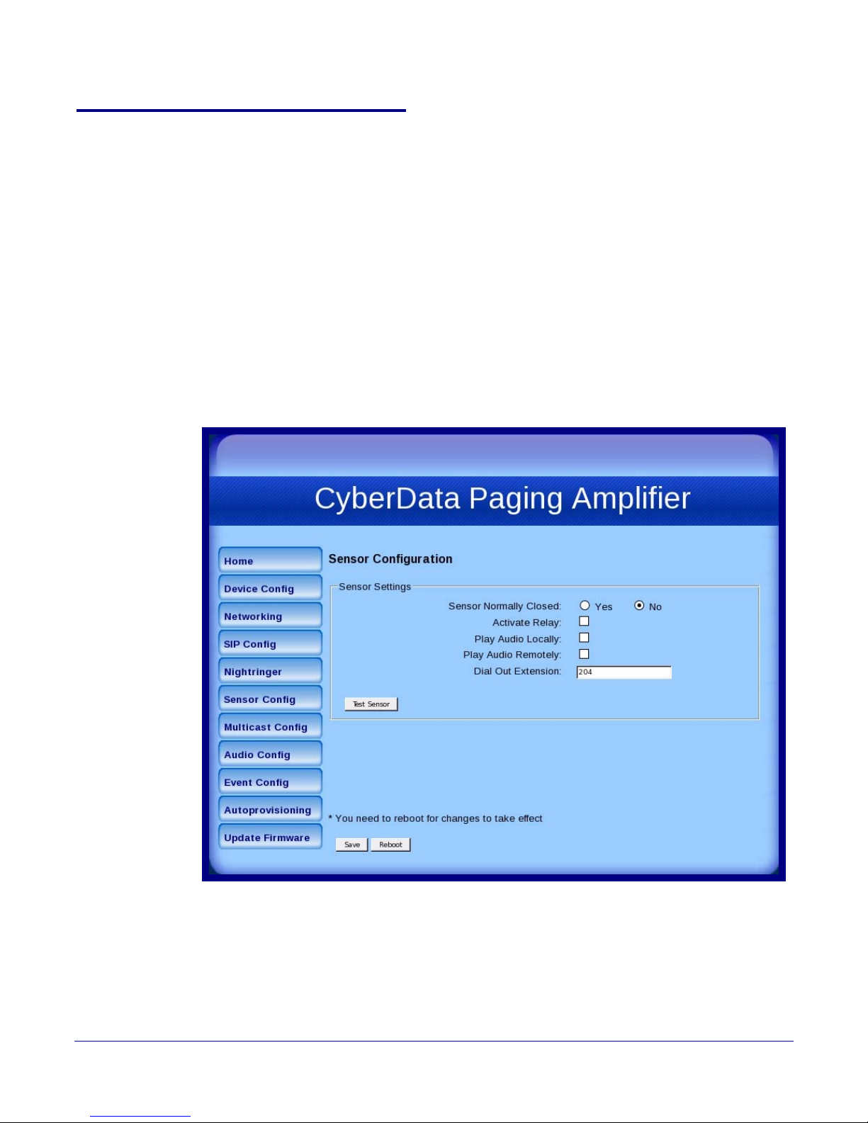
The sensor (pins 1 and 2) on the header can be used to monitor something’s open or closed state.
There is an option on the Sensor Configuration page to trigger on an open or short condition on
these pins.
For the sensor there are three actions that the Loudspeaker Amplifier can do:
● Activate the relay until the sensor is deactivated
● Loop an audio file until the sensor is deactivated
● Call a preset extension and play a pre-recorded audio file (loops until user hangs up)
Note Calling a preset extension can be set up as a point-to-point call, but currently can't send
delayed DTMF tones.
1. Click Sensor Config to open the Sensor Configuration page (Figure 2-24).
Figure 2-24. Sensor Configuration Page
32
Operations Guide 930361G CyberData Corporation
Page 40
Installing the VoIP V2 Loudspeaker Amplifier
Configure the Loudspeaker Amplifier Parameters
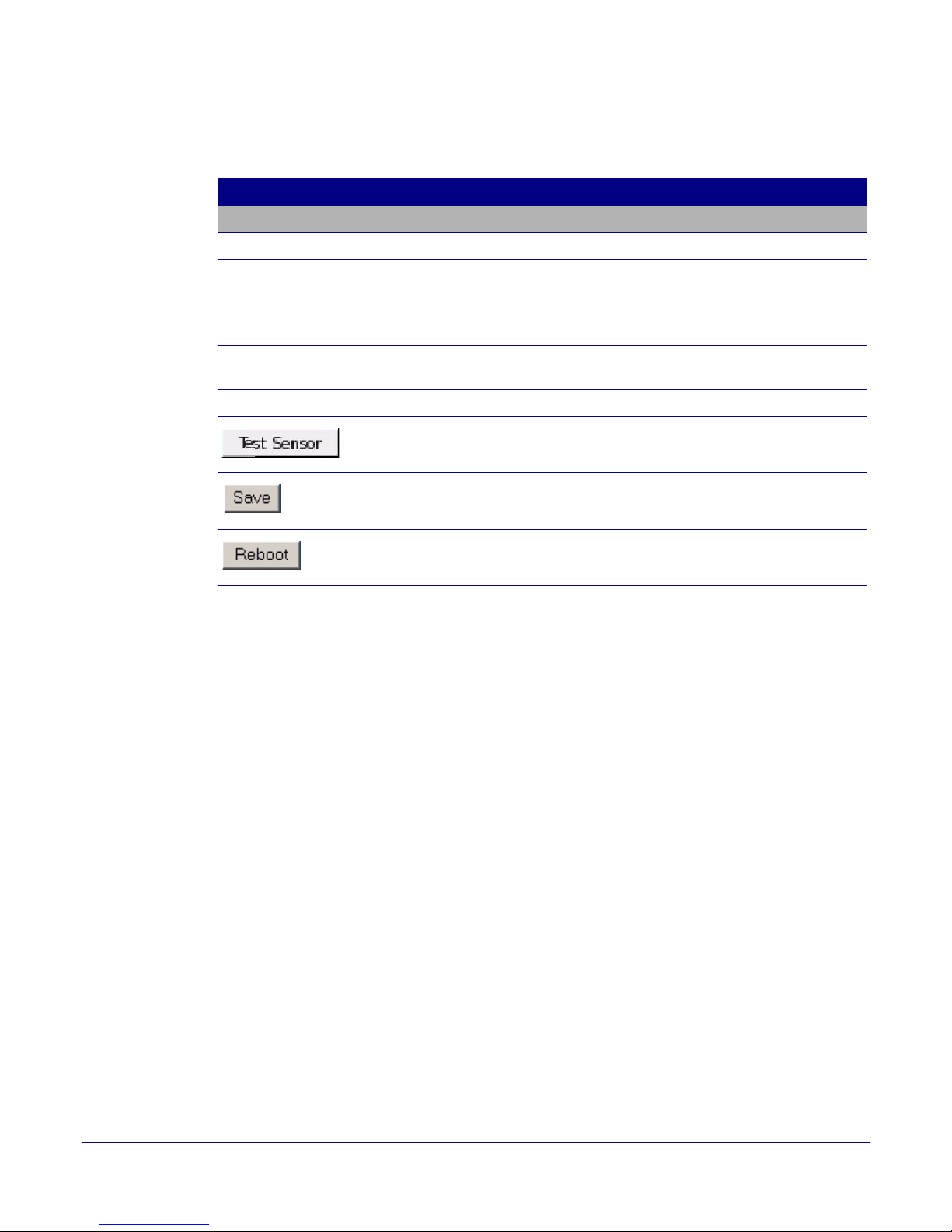
2. On the Sensor Configuration page, enter values for the parameters indicated in Ta bl e 2-15.
Table 2-15. Sensor Configuration Parameters
Web Page Item Description
Sensor Settings
Sensor Normally Closed Select the inactive state of the sensors.
Activate Relay Check this box to activate the relay until the sensor is
deactivated.
Play Audio Locally Check this box to loop an audio file until the sensor is
deactivated.
Play Audio Remotely Check this box to make only one call to a preset extension
and play a pre-recorded audio file repeatedly.
Dial Out Extension Enter the dial-out extension number.
Use this button to test the sensor.
Click the Save button to save your configuration settings.
Note: You need to reboot for changes to take effect.
33
Click on the Reboot button to reboot the system.
3. After changing the parameters, click Save Settings.
Operations Guide 930361G CyberData Corporation
Page 41

Installing the VoIP V2 Loudspeaker Amplifier
Configure the Loudspeaker Amplifier Parameters
2.3.8 Configure the Multicast Configuration Parameters
Multicast groups use multicasting to create public address paging zones. Multicasting is based on
the concept of a group. Multicast addresses specify an arbitrary group of IP hosts that have joined
the group and want to receive traffic sent to the group. Group members send IGMP messages to
their local multicast routers, allowing the group traffic traversal from the source.
Multicast configuration provides the ability to join up to 10 paging zones. A paging zone can consist
of one, or many, CyberData multicast group-enabled Loudspeaker Amplifiers. There is no limit to
how many Loudspeaker Amplifiers can be in a given paging zone. Each multicast group is defined
by a multicast address and port number. Each multicast group is also assigned a priority, allowing
simultaneously arriving pages to be serviced based on importance. Multicast groups are compatible
with IGMP through version 3.
Note The Loudspeaker Amplifier supports simultaneous SIP and Multicast.
34
Operations Guide 930361G CyberData Corporation
Page 42
Installing the VoIP V2 Loudspeaker Amplifier
Configure the Loudspeaker Amplifier Parameters
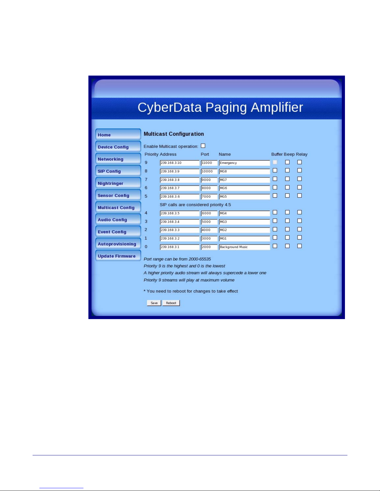
1. Click on the Multicast Configuration button to open the Multicast Configuration page. See
Figure 2-25.
Figure 2-25. Multicast Configuration Setup
35
Operations Guide 930361G CyberData Corporation
Page 43
Installing the VoIP V2 Loudspeaker Amplifier
Configure the Loudspeaker Amplifier Parameters
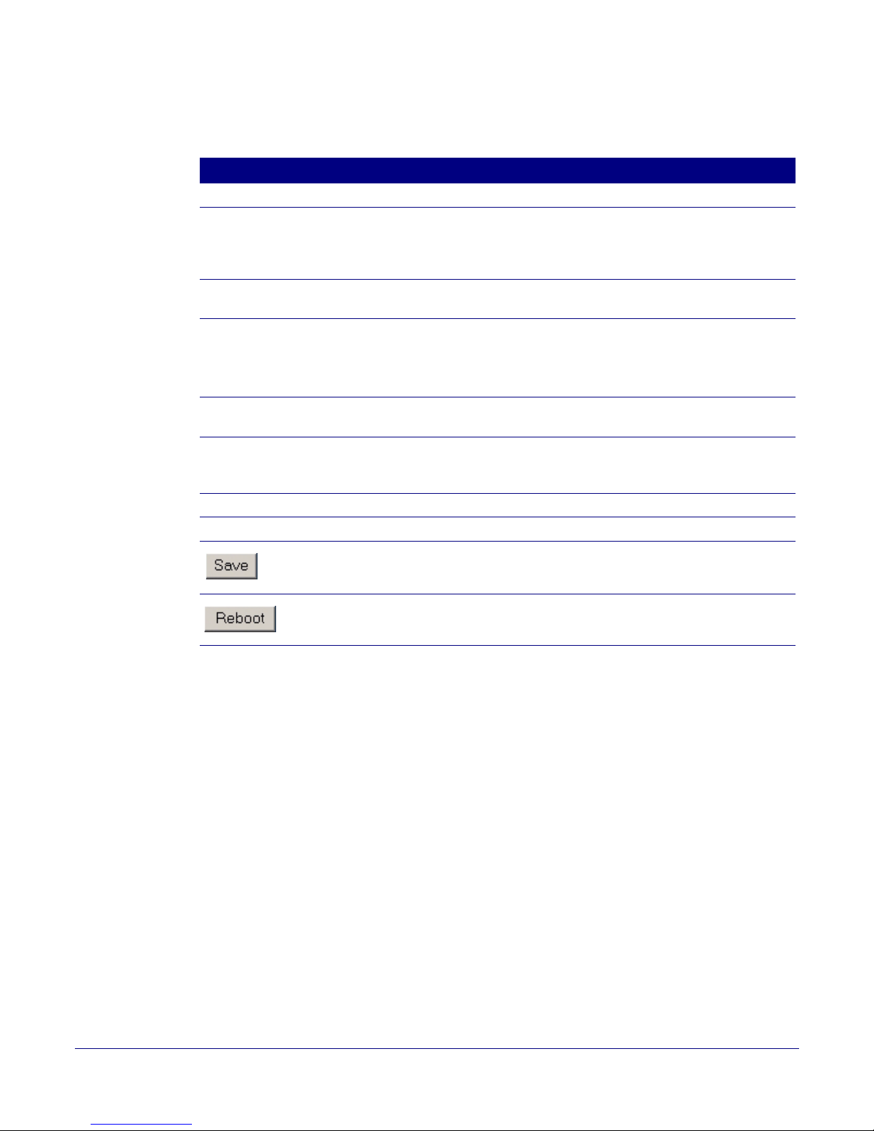
2. On the Multicast Configuration page, enter values for the parameters indicated in Tab le 2-16.
Table 2-16. Multicast Configuration Parameters
Web Page Item Description
Enable Multicast Operation Enables or disables multicast operation.
Priority Indicates the priority for the multicast group. Priority 9 is the
highest (emergency streams). 0 is the lowest (background
music). See
Section 2.3.8.1, "Assigning Priority" for more
details.
Address Enter the multicast IP Address for this multicast group
(15 character limit).
Port (range can be from 2000 to 65535) Enter the port number for this multicast group (5 character
limit).
Note: The multicast ports have to be even values. The
webpage will enforce this restriction.
Name Assign a descriptive name for this multicast group (25
character limit).
Buffer When buffering is enabled for a multicast stream, it will store
any audio received on this socket to memory and play it back
when the stream is stopped or the buffer is full.
36
Beep Enable or disable the tone (beep) for a multicast stream.
Relay Enable or disable the relay for a multicast stream.
Click the Save button to save your configuration settings.
Note: You need to reboot for changes to take effect.
Click on the Reboot button to reboot the system.
3. After changing the parameters, click on the Save button.
Operations Guide 930361G CyberData Corporation
Page 44

2.3.8.1 Assigning Priority
When playing multicast streams, audio on different streams will preempt each other according to
their priority in the list. An audio stream with a higher priority will interrupt a stream with a lower
priority.
If both SIP and Multicast is enabled, SIP audio streams are considered priority 4.5. SIP audio will
interrupt multicast streams with priority 0 through 4 and will be interrupted by multicast streams
with priority 5 through 9.
During priority 9 multicast streams, the analog volume control is bypassed and the volume level is
set to maximum.
Line In audio is considered the lowest priority, so it will be muted if there are any multicast or SIP
audio streams playing.
For example, if the test audio button on the Device Config page is pressed while music is playing via
the Enabled Line In feature, the music will be muted during the test audio message.
Note SIP calls, buffered SIP calls, multicast streams, buffered multicast streams, ring tones,
ringback tones, and nightring tones are all prioritized.
Installing the VoIP V2 Loudspeaker Amplifier
Configure the Loudspeaker Amplifier Parameters
37
Ringtones and
Nightringtones
Lengthy Pages
Buffered Audio
Ringtones all play at the same priority level. This means that it is possible to have a nightring tone
and a normal ringtone playing at the same time.
The maximum ringtone duration is 2,097,152 bytes or about four minutes of ulaw audio.
Concerning how lengthy pages are handled (where someone puts the phone down for 15 minutes),
after the 2MB limit is reached, further data will be thrown away while the audio file is played back.
When the file is done playing, it will stop throwing away input and begin buffering data for another
four minutes.
Therefore, with the buffered mode enabled on a stream playing background music, you will hear the
following sequence of events:
1. Four minutes of silence.
2. Music from 0:00 through 4:00.
3. Four minutes of silence.
4. Music from 8:00 through 12:00 and so on.
When the device is playing back buffered audio and this buffered audio is interrupted by a higher
priority stream, once the higher priority streams is finished, the device will restart the lower priority
stream from the beginning.
Operations Guide 930361G CyberData Corporation
Page 45
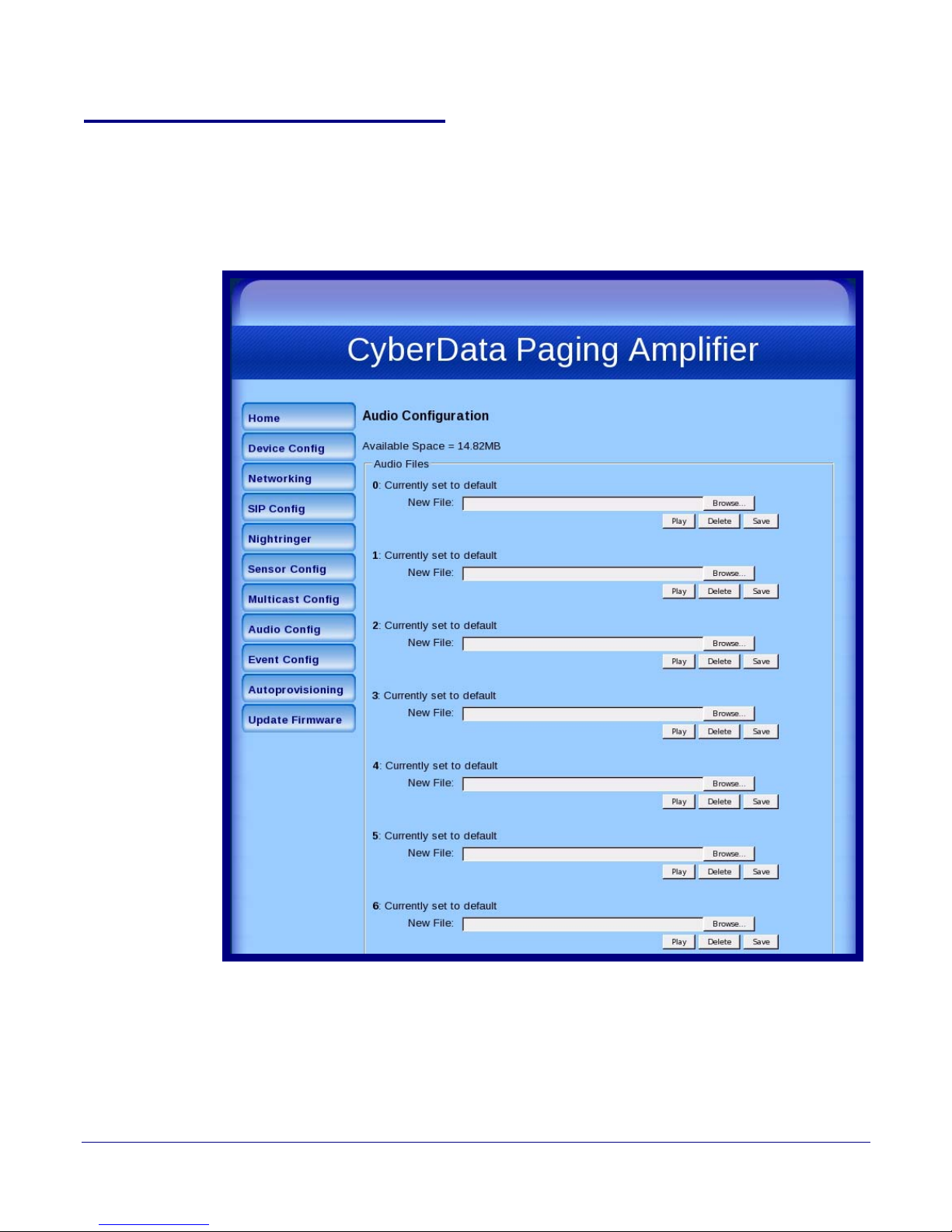
2.3.9 Configure the Audio Parameters
Click the Audio Config button to open the Audio Configuration page. The Audio Configuration
page is used to add custom audio to the board. User uploaded audio will take precedence over the
audio files shipped with the Loudspeaker Amplifier.
Figure 2-26. Audio Configuration Page
Installing the VoIP V2 Loudspeaker Amplifier
Configure the Loudspeaker Amplifier Parameters
38
Operations Guide 930361G CyberData Corporation
Page 46
Installing the VoIP V2 Loudspeaker Amplifier
Configure the Loudspeaker Amplifier Parameters
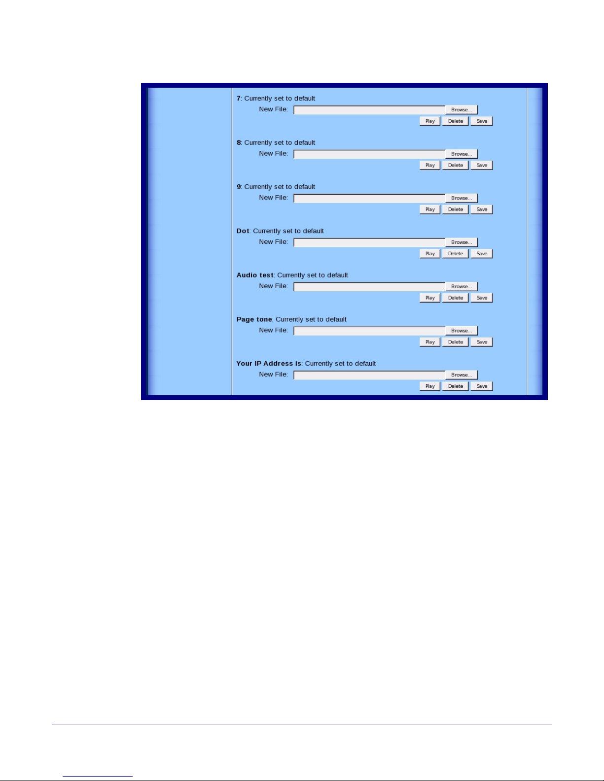
Figure 2-27. Audio Configuration Page (continued)
39
Operations Guide 930361G CyberData Corporation
Page 47
Installing the VoIP V2 Loudspeaker Amplifier
Configure the Loudspeaker Amplifier Parameters
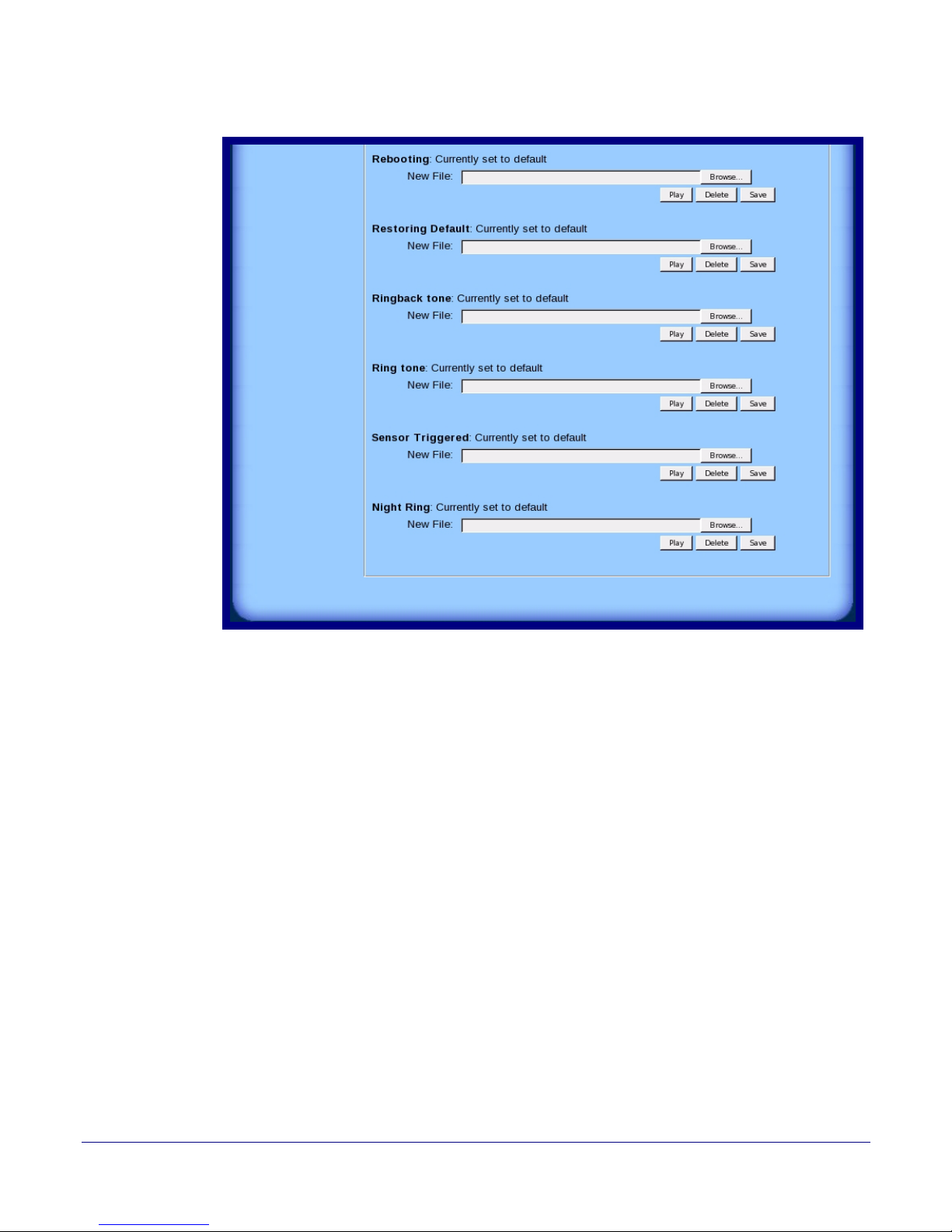
Figure 2-28. Audio Configuration Page (continued)
40
Operations Guide 930361G CyberData Corporation
Page 48

Installing the VoIP V2 Loudspeaker Amplifier
Configure the Loudspeaker Amplifier Parameters
On the Audio Configuration page, enter values for the parameters indicated in Ta bl e 2-17.
Note Each entry on the Audio Configuration page replaces one of the stock audio files on the
board. When the input box displays the word default, the Loudspeaker Amplifier is using
the stock audio file. If that file is replaced with a user file, it will display the uploaded
filename.
Table 2-17. Audio Configuration Parameters
Web Page Item Description
Audio Files
0-9 The name of the audio configuration option is the same as the spoken
audio that plays on the board (24 character limit).
'0' corresponds to the spoken word “zero.”
'1' corresponds to the spoken word “one.”
'2' corresponds to the spoken word “two.”
'3' corresponds to the spoken word “three.”
'4' corresponds to the spoken word “four.”
'5' corresponds to the spoken word “five.”
'6' corresponds to the spoken word “six.”
'7' corresponds to the spoken word “seven.”
'8' corresponds to the spoken word “eight.”
'9' corresponds to the spoken word “nine.”
Dot Corresponds to the spoken word “dot.” (24 character limit)
41
Audiotest Corresponds to the message “This is the CyberData IP speaker test
message...” (24 character limit)
Pagetone Corresponds to a simple tone that is unused by default (24 character limit).
Your IP Address is Corresponds to the message “Your IP address is...” (24 character limit).
Rebooting Corresponds to the spoken word “Rebooting” (24 character limit).
Restoring default Corresponds to the message “Restoring default” (24 character limit).
Ringback Tone Corresponds to the ringback tone that plays when calling a remote
extension (24 character limit).
Ring Tone Corresponds to the tone that plays when set to ring when receiving a call
(24 character limit).
Sensor Triggered Corresponds to the sensor when it is triggered (24 character limit).
Night Ring Specifies the ringtone for Night Ringer. By default this parameter uses the
same audio file that is selected for the Ring Tone parameter.
The Browse button will allow you to navigate to and select an audio file.
The Play button will play that audio file.
The Delete button will delete any user uploaded audio and restore the
stock audio file.
Operations Guide 930361G CyberData Corporation
Page 49

Installing the VoIP V2 Loudspeaker Amplifier
Configure the Loudspeaker Amplifier Parameters
Table 2-17. Audio Configuration Parameters (continued)
Web Page Item Description
The Save button will download a new user audio file to the board once
you've selected the file by using the Browse button. The Save button will
delete any pre-existing user-uploaded audio files.
42
Operations Guide 930361G CyberData Corporation
Page 50
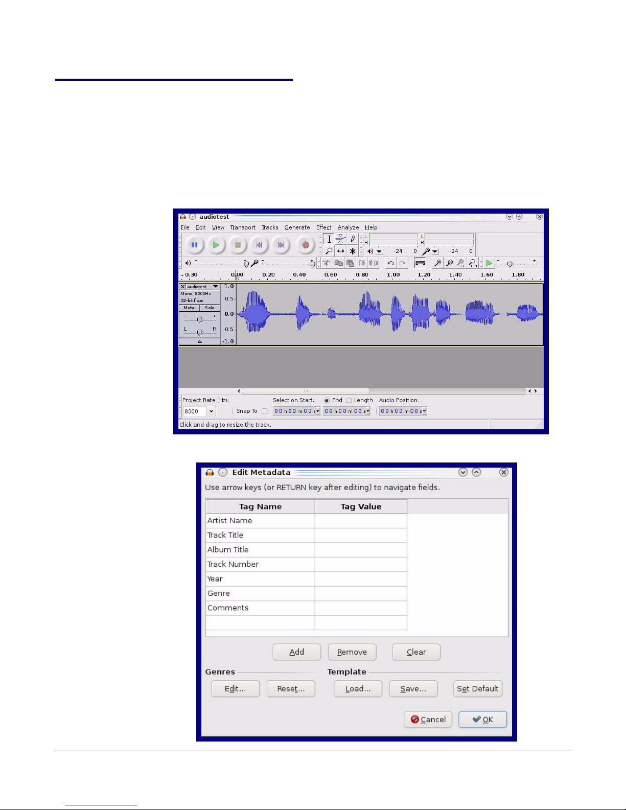
2.3.10 User-created Audio Files
User created audio files should be saved in the following format:
RIFF (little-endian) data, WAVE audio, Microsoft PCM, 16 bit, mono 8000 Hz
You can use the free utility Audacity to convert audio files into this format. See Figure 2-29 through
Figure 2-31.
Installing the VoIP V2 Loudspeaker Amplifier
Configure the Loudspeaker Amplifier Parameters
Figure 2-29. Audacity 1
43
Figure 2-30. Audacity 2
Operations Guide 930361G CyberData Corporation
Page 51
Installing the VoIP V2 Loudspeaker Amplifier
WAV (Microsoft) signed 16 bit PCM
Configure the Loudspeaker Amplifier Parameters
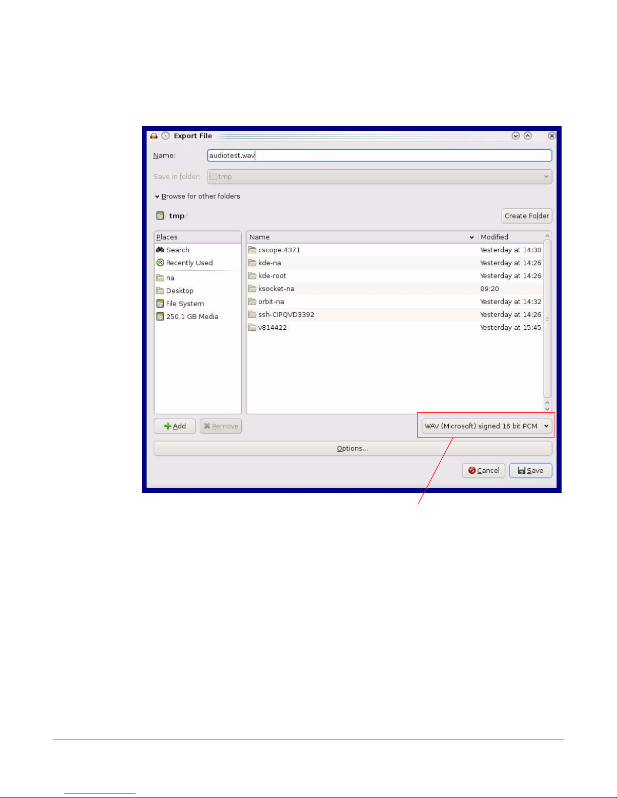
When you export an audio file with Audacity, save the output as:
● WAV (Microsoft) signed 16 bit PCM.
Figure 2-31. WAV (Microsoft) signed 16 bit PCM
44
Operations Guide 930361G CyberData Corporation
Page 52
2.3.11 Configure the Event Parameters
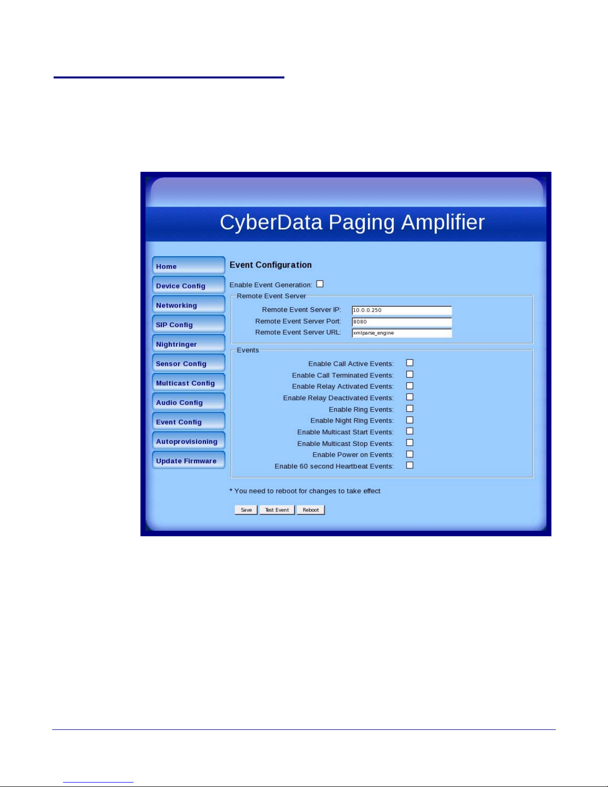
Click the Event Config button to open the Event Configuration page (Figure 2-32). The Event
Configuration page specifies a remote server that can be used to receive HTTP POST events when
actions take place on the board.
Figure 2-32. Event Configuration Page
Installing the VoIP V2 Loudspeaker Amplifier
Configure the Loudspeaker Amplifier Parameters
45
Operations Guide 930361G CyberData Corporation
Page 53
Installing the VoIP V2 Loudspeaker Amplifier
Configure the Loudspeaker Amplifier Parameters
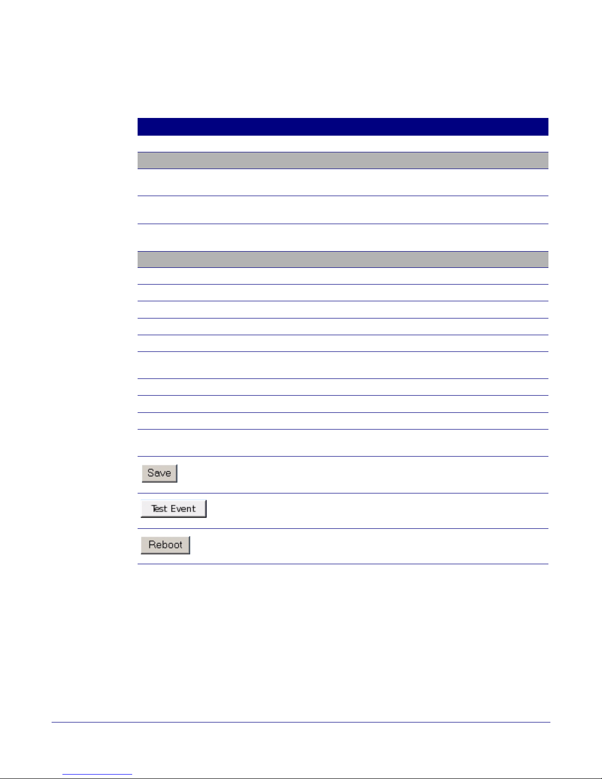
Ta bl e 2-18 shows the web page items on the Event Configuration page.
Table 2-18. Event Configuration
Web Page Item Description
Enable Event Generation When selected, Event Generation is enabled.
Remote Event Server
Remote Event Server IP Type the Remote Event Server IP address.
(64 character limit)
Remote Event Server Port Type the Remote Event Server port number.
(0 - 65535)
Remote Event Server URL Type the Remote Event Server URL.
(127 character limit)
Events
Enable Call Active Events When selected, Call Active Events are enabled.
Enable Call Terminated Events When selected, Call Terminated Events are enabled.
Enable Relay Activated Events When selected, Relay Activated Events are enabled.
46
Enable Relay Deactivated Events When selected, Relay Deactivated Events are enabled.
Enable Ring Events When selected, Ring Events are enabled.
Enable Night Ring Events When selected, there is a notification when the device
receives a night ring.
Enable Multicast Start Events When selected, Multicast Start Events are enabled.
Enable Multicast Stop Events When selected, Multicast Stop Events are enabled.
Enable Power On Events When selected, Power On Events are enabled.
Enable 60 Second Heartbeat Events When selected, 60 Second Heartbeat Events are
enabled.
Click the Save button to save your configuration settings.
Note: You need to reboot for changes to take effect.
Click on the Test Event button to test an event.
Click on the Reboot button to reboot the system.
Operations Guide 930361G CyberData Corporation
Page 54

2.3.11.1 Example Packets for Events
The server and port are used to point to the listening server and the 'Remote Event Server URL' is
the destination URL (typically the script running on the remote server that's used to parse and
process the POST events).
Note The XML is URL-encoded before transmission so the following examples are not completely
accurate.
Here are example packets for every event:
POST xmlparse_engine HTTP/1.1
Host: 10.0.3.79
User-Agent: CyberData/1.0.0
Content-Length: 197
Content-Type: application/x-www-form-urlencoded
<?xml version="1.0" encoding="ISO-8859-1"?>
<cyberdata NAME='CyberData VoIP Device' MAC='0020f70015b6'>
<event>POWERON</event>
</cyberdata>
Installing the VoIP V2 Loudspeaker Amplifier
Configure the Loudspeaker Amplifier Parameters
47
POST xmlparse_engine HTTP/1.1
Host: 10.0.3.79
User-Agent: CyberData/1.0.0
Content-Length: 199
Content-Type: application/x-www-form-urlencoded
<?xml version="1.0" encoding="ISO-8859-1"?>
<cyberdata NAME='CyberData VoIP Device' MAC='0020f70015b6'>
<event>HEARTBEAT</event>
</cyberdata>
POST xmlparse_engine HTTP/1.1
Host: 10.0.3.79
User-Agent: CyberData/1.0.0
Content-Length: 196
Content-Type: application/x-www-form-urlencoded
<?xml version="1.0" encoding="ISO-8859-1"?>
<cyberdata NAME='CyberData VoIP Device' MAC='0020f70015b6'>
<event>BUTTON</event>
</cyberdata>
POST xmlparse_engine HTTP/1.1
Host: 10.0.3.79
User-Agent: CyberData/1.0.0
Content-Length: 201
Content-Type: application/x-www-form-urlencoded
<?xml version="1.0" encoding="ISO-8859-1"?>
<cyberdata NAME='CyberData VoIP Device' MAC='0020f70015b6'>
<event>CALL_ACTIVE</event>
</cyberdata>
POST xmlparse_engine HTTP/1.1
Host: 10.0.3.79
Operations Guide 930361G CyberData Corporation
Page 55

Installing the VoIP V2 Loudspeaker Amplifier
Configure the Loudspeaker Amplifier Parameters
User-Agent: CyberData/1.0.0
Content-Length: 205
Content-Type: application/x-www-form-urlencoded
<?xml version="1.0" encoding="ISO-8859-1"?>
<cyberdata NAME='CyberData VoIP Device' MAC='0020f70015b6'>
<event>CALL_TERMINATED</event>
</cyberdata>
POST xmlparse_engine HTTP/1.1
Host: 10.0.3.79
User-Agent: CyberData/1.0.0
Content-Length: 197
Content-Type: application/x-www-form-urlencoded
<?xml version="1.0" encoding="ISO-8859-1"?>
<cyberdata NAME='CyberData VoIP Device' MAC='0020f70015b6'>
<event>RINGING</event>
</cyberdata>
POST xmlparse_engine HTTP/1.1
Host: 10.0.3.79
User-Agent: CyberData/1.0.0
Content-Length: 234
Content-Type: application/x-www-form-urlencoded
48
<?xml version="1.0" encoding="ISO-8859-1"?>
<cyberdata NAME='CyberData VoIP Device' MAC='0020f70015b6'>
<event>MULTICAST_START</event>
<index>8</index>
</cyberdata>
POST xmlparse_engine HTTP/1.1
Host: 10.0.3.79
User-Agent: CyberData/1.0.0
Content-Length: 233
Content-Type: application/x-www-form-urlencoded
<?xml version="1.0" encoding="ISO-8859-1"?>
<cyberdata NAME='CyberData VoIP Device' MAC='0020f70015b6'>
<event>MULTICAST_STOP</event>
<index>8</index>
</cyberdata>
POST xmlparse_engine HTTP/1.1
Host: 10.0.3.79
User-Agent: CyberData/1.0.0
Content-Length: 234
Content-Type: application/x-www-form-urlencoded
<?xml version="1.0" encoding="ISO-8859-1"?>
<cyberdata NAME='CyberData VoIP Device' MAC='0020f70015b6'>
<event>RELAY_ACTIVATED</event>
</cyberdata>
POST xmlparse_engine HTTP/1.1
Host: 10.0.3.79
Operations Guide 930361G CyberData Corporation
Page 56

Installing the VoIP V2 Loudspeaker Amplifier
Configure the Loudspeaker Amplifier Parameters
User-Agent: CyberData/1.0.0
Content-Length: 234
Content-Type: application/x-www-form-urlencoded
<?xml version="1.0" encoding="ISO-8859-1"?>
<cyberdata NAME='CyberData VoIP Device' MAC='0020f70015b6'>
<event>RELAY_DEACTIVATED</event>
</cyberdata>
POST xmlparse_engine HTTP/1.1
Host: 10.0.3.79
User-Agent: CyberData/1.0.0
Content-Length: 234
Content-Type: application/x-www-form-urlencoded
<?xml version="1.0" encoding="ISO-8859-1"?>
<cyberdata NAME='CyberData VoIP Device' MAC='0020f70015b6'>
<event>NIGHTRINGING</event>
</cyberdata>
49
Operations Guide 930361G CyberData Corporation
Page 57
Configure the Loudspeaker Amplifier Parameters
2.3.12 Configure the Autoprovisioning Parameters
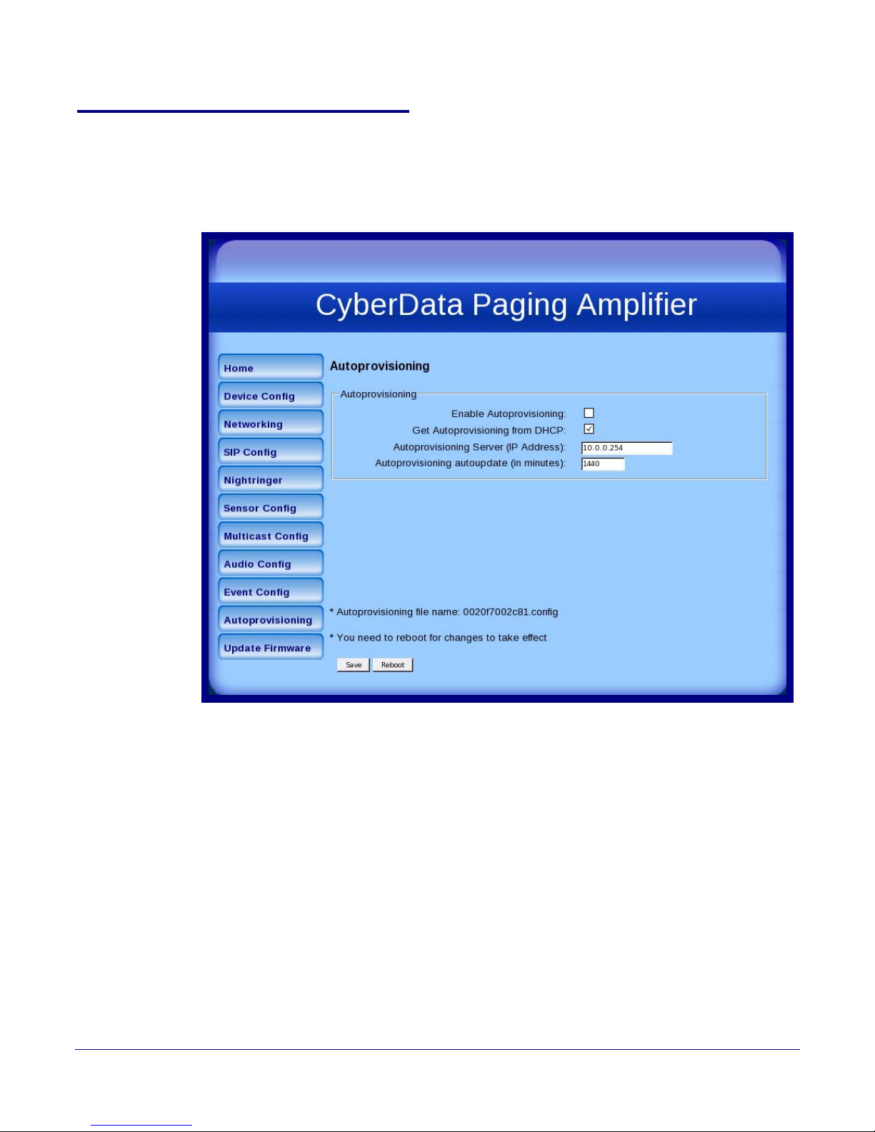
1. Click the Autoprovisioning button to open the Autoprovisioning Configuration page.
See Figure 2-20.
Figure 2-33. Autoprovisioning Configuration Page
Installing the VoIP V2 Loudspeaker Amplifier
50
Operations Guide 930361G CyberData Corporation
Page 58
Installing the VoIP V2 Loudspeaker Amplifier
Configure the Loudspeaker Amplifier Parameters
2. On the Autoprovisioning Configuration page, you may enter values for the parameters
indicated in
Ta bl e 2-11.
Table 2-19. Autoprovisioning Configuration Parameters
Web Page Item Description
Autoprovisioning
Enable Autoprovisioning See Section 2.3.12.1, "Autoprovisioning".
Get Autoprovisioning from DHCP See Section 2.3.12.1, "Autoprovisioning".
Autoprovisioning Server (IP Address) See Section 2.3.12.1, "Autoprovisioning" (15 character limit).
51
Autoprovisioning Autoupdate
(in minutes)
Type the desired time (in minutes) that you want the
Autoprovisioning feature to update (6 character limit).
Click the Save button to save your configuration settings.
Note: You need to reboot for changes to take effect.
Click on the Reboot button to reboot the system.
3. After changing the parameters, click the Save button.
Operations Guide 930361G CyberData Corporation
Page 59

2.3.12.1 Autoprovisioning
Installing the VoIP V2 Loudspeaker Amplifier
Configure the Loudspeaker Amplifier Parameters
52
Enable
Autoprovisioning
Option
Networking
Get
Autoprovisioning
from DHCP
With autoprovisioning enabled, the board will get its configuration from a remote TFTP server on
startup or periodically on a scheduled delay. Autoprovisioned values will override values stored in
on-board memory and will be visible on the web page. The board gets its autoprovisioning
information from an XML-formatted file hosted from a TFTP server. CyberData will provide a
template for this XML file and the user can modify it for their own use.
To use autoprovisioning, create a copy of the autoprovisioning template with the desired settings
and name this file with the mac address of the device to configure (for example:
0020f7350058.config). Put this file into your TFTP server directory and manually set the TFTP server
address on the board.
It is not necessary to set every option found in the autoprovisioning template. As long as the XML is
valid, the file can contain any subset. Options not autoprovisioned will default to the values stored
in the on board memory. For example if you only wanted to modify the device name, the following
would be a valid autoprovisioning file:
<?xml version="1.0" encoding="utf-8" ?>
<specific>
<MiscSettings>
<DeviceName>auto V2 Paging Amplifier</DeviceName>
</MiscSettings>
</specific>
The board will only apply networking settings or firmware upgrades after a reboot.
When this option is checked, the device will automatically fetch its autoprovisioning server address
from the DHCP server. The device will use the address specified in OPTION 150 (TFTP-servername) or OPTION 66. If both options are set, the device will use OPTION 150.
Refer to the documentation of your DHCP server for setting up OPTION 150.
Operations Guide 930361G CyberData Corporation
Page 60

Installing the VoIP V2 Loudspeaker Amplifier
Configure the Loudspeaker Amplifier Parameters
To set up a Linux DHCPD server to serve autoprovisioning information (in this case using both
option 66 and 150), here's an example dhcpd.conf:
# dhcpd.conf
#
# Configuration file for ISC dhcpd (see 'man dhcpd.conf')
#
ddns-update-style ad-hoc;
option option-150 code 150 = ip-address;
subnet 10.0.0.0 netmask 255.0.0.0 {
max-lease-time 120;
default-lease-time 120;
option routers 10.0.0.1;
option subnet-mask 255.0.0.0;
option domain-name "voiplab";
option domain-name-servers 10.0.0.1;
option time-offset -8; # Pacific Standard Time
option tftp-server-name "10.0.0.254";
53
Autoprovisioning
Server (IP Address)
Autoprovisioning
Autoupdate
Autoprovisioned
Firmware Upgrades
option option-150 10.0.0.254;
range 10.10.0.1 10.10.2.1;}
Instead of using DHCP to provide the autoprovisioning tftp server address, you can specify an
address manually.
If Autoprovisioning is enabled and the Autoprovisioning Autoupdate value is something other
than 0 minutes, a service is started on startup that will wait the configured number of minutes and
then try to re-download its autoprovisioning file. It will compare its previously autoprovisioned file
with this new file and if there are differences, it will reboot the board.
An Autoprovisioned firmware upgrade only happens after a reboot, will take roughly three
minutes, and the web page will be unresponsive during this time.
The 'FirmwareVersion' value in the xml file must match the version stored in the 'FirmwareFile'.
<FirmwareVersion>v5.0.5b01</FirmwareVersion>
<FirmwareFile>505b01-uImage-ceilingspeak</FirmwareFile>
If these values are mismatched, the board can get stuck in a loop where it goes through the
following sequence of actions:
1. The board downloads and writes a new firmware file.
2. After the next reboot, the board recognizes that the firmware version does not match.
3. The board downloads and writes the firmware file again.
CyberData has timed a firmware upgrade at 140 seconds. Therefore, if you suspect the board is
stuck in a loop, either remove or comment out the FirmwareVersion line in the XML file and let the
board boot as it normally does.
Operations Guide 930361G CyberData Corporation
Page 61

Installing the VoIP V2 Loudspeaker Amplifier
Configure the Loudspeaker Amplifier Parameters
54
Autoprovisioned
Audio Files
Audio files are stored in non-volatile memory and an autoprovisioned audio file will only have to be
downloaded once for each device. Loading many audio files to the device from the web page could
cause it to appear unresponsive. If this happens, wait until the transfer is complete and then refresh
the page.
The device uses the file name to determine when to download a new audio file. This means that if
you used autoprovisioning to upload a file and then changed the contents of this file at the TFTP
server, the device will not recognize that the file has changed (because the file name is the same).
Since audio files are stored in non-volatile memory, if autoprovisioning is disabled after they have
been loaded to the board, the audio file settings will not change. You can force a change to the audio
files on the board by clicking Restore Default on the Audio Configuration page or by changing the
autoprovisioning file with “default” set as the file name.
Operations Guide 930361G CyberData Corporation
Page 62

Installing the VoIP V2 Loudspeaker Amplifier
Configure the Loudspeaker Amplifier Parameters
2.3.13 Upgrade the Firmware and Reboot the Loudspeaker Amplifier
To upload the Loudspeaker Amplifier firmware from your PC:
1. Retrieve the latest Loudspeaker Amplifier firmware from the VoIP V2 Loudspeaker Amplifier
Downloads page at:
http://www.cyberdata.net/products/voip/digitalanalog/loudspeakerampv2/downloads.html
2. Unzip the Loudspeaker Amplifier version file. This file may contain the following:
•Firmware file
• Release notes
3. Log in to the Loudspeaker Amplifier home page as instructed in Section 2.3.2, "Log in to the
Configuration Home Page".
55
Operations Guide 930361G CyberData Corporation
Page 63
Installing the VoIP V2 Loudspeaker Amplifier
Configure the Loudspeaker Amplifier Parameters
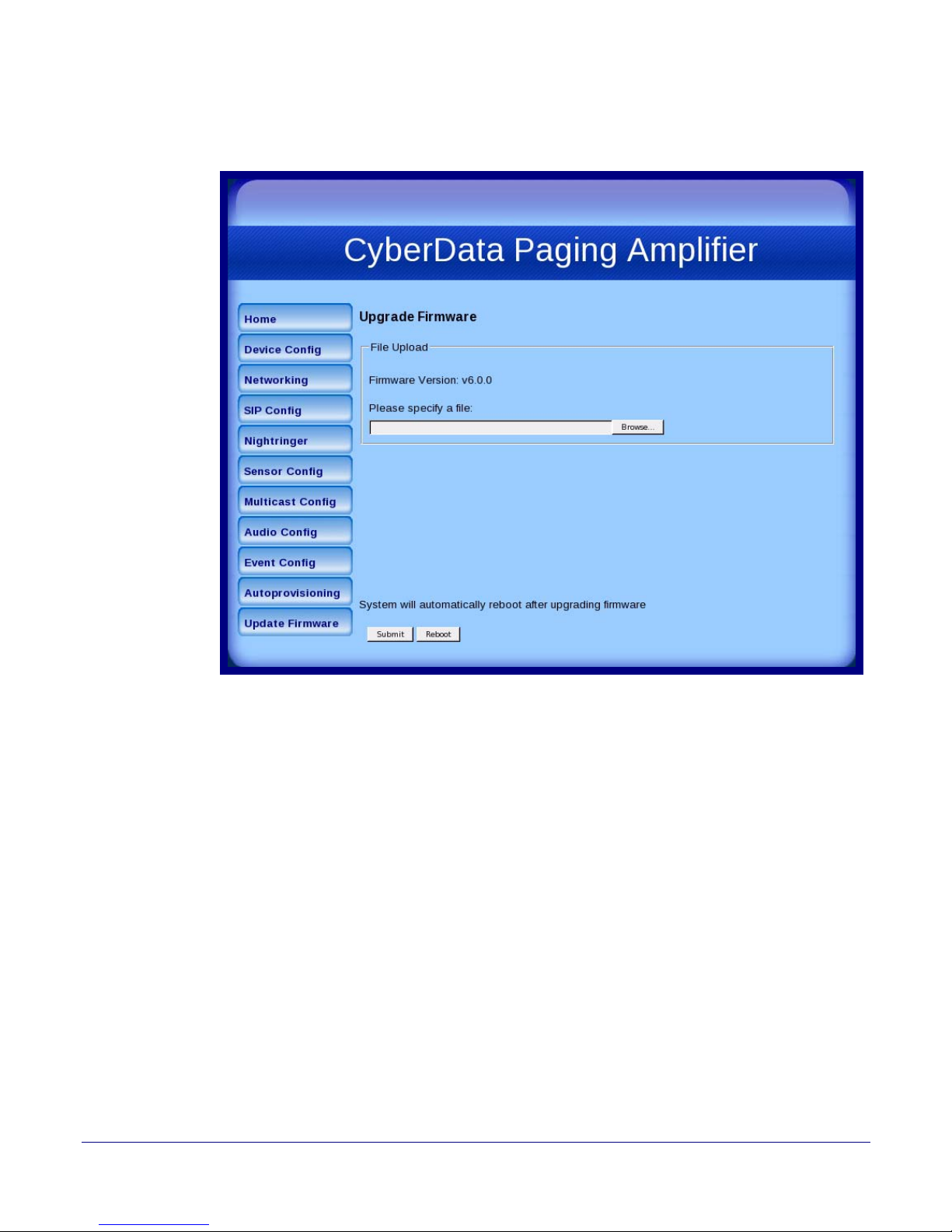
4. Click the Update Firmware button to open the Upgrade Firmware page. See Figure 2-34.
Figure 2-34. Upgrade Firmware P a ge
56
5. Click Browse, and then navigate to the location of the Loudspeaker Amplifier firmware file.
6. Click Submit.
Note This starts the upload process. Once the Loudspeaker Amplifier has uploaded the file, the
Uploading Firmware countdown page appears, indicating that the firmware is being
written to flash. The Loudspeaker Amplifier will automatically reboot when the upload is
complete. When the countdown finishes, the Upgrade Firmware page will refresh. The
uploaded firmware filename should be displayed in the system configuration (indicating
successful upload and reboot).
Operations Guide 930361G CyberData Corporation
Page 64
Installing the VoIP V2 Loudspeaker Amplifier
Configure the Loudspeaker Amplifier Parameters
Ta bl e 2-20 shows the web page items on the Upgrade Firmware page.
Table 2-20. Upgrade Firmware Parameters
Web Page Item Description
Firmware Version Shows the current firmware version.
Use the Browse button to navigate to the location of the
Intercom firmware file that you want to upload.
Click on the Submit button to automatically upload the
selected firmware and reboot the system.
Click on the Reboot button to reboot the system.
57
Operations Guide 930361G CyberData Corporation
Page 65
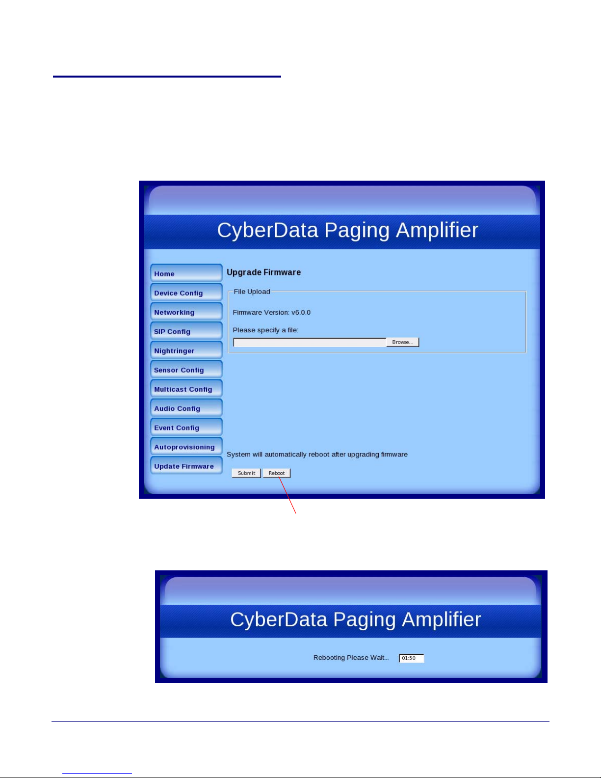
2.3.14 Reboot the Loudspeaker Amplifier
Reboot
To reboot a Loudspeaker Amplifier, log in to the web page as instructed in Section 2.3.2, "Log in to
the Configuration Home Page".
1. Click Update Firmware to open the Upgrade Firmware page (Figure 2-35).
Figure 2-35. Upgrade Firmware P a ge
Installing the VoIP V2 Loudspeaker Amplifier
Configure the Loudspeaker Amplifier Parameters
58
2. Click Reboot. A normal restart will occur and you will see the following Reboot page.
Operations Guide 930361G CyberData Corporation
Figure 2-36. Reboot Page
Page 66

Appendix A: Mounting the Amplifier
A.1 Mount the Amplifier
Before you mount the enclosure, make sure that you have received all of the parts for each
enclosure. Refer to
Quantity Part Name Illustration
3 #6 Plastic Ribbed Anchors
3 #6 Sheet Metal Screws
Tab le A-21.
Table A-21. Wall Mounting Components (Part of the Accessory Kit)
59
Note The Loudspeaker Amplifier was designed for indoor use. Mounting it on the external part
of a building will require additional hardware for weatherproofing, cabling access, and
lightning suppression. Consult a certified electrician for details.
Note For mounting, use the three #6 SHEET METAL SCREWS to secure the enclosure.
Operations Guide 930361G CyberData Corporation
Page 67
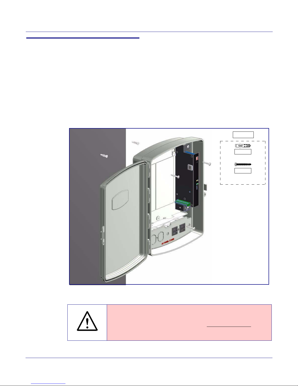
A.1.1 Mounting the Enclosure
071057A
PHILLIP SCREW (3x)
#6x1 1/4" PAN HEAD
#6 PLASTIC ANCHOR (3x)
151014
531032
GENERAL ALERT
To mount the enclosure:
1. Prepare holes for the screws.
2. Plug in the power adapter and use the green Power light to verify that the power is on.
3. Plug the Ethernet cable into the Loudspeaker Amplifier. The yellow Link light verifies the
network connection.
4. For wall mounting, use the three #6 x 1-1/4-inch Pan Head Phillip screws to secure the speaker.
Figure A-1..
See
Figure A-1. Mounting the Enclosure
60
Mount the Amplifier
Wiring the 125V AC Plug
Operations Guide 930361G CyberData Corporation
Caution
Equipment Caution: The green wire with the yellow stripe is a ground conne ction
for Electrostatic Discharge (E S D) pr otection, and
To wire the 125V AC plug, consult a licensed electr ician and the local building
codes in your area.
should not be removed.
Page 68

Appendix B: Setting up a TFTP Server
B.1 Set up a TFTP Server
Autoprovisioning requires a TFTP server for hosting the configuration file.
B.1.1 In a LINUX Environment
To set up a TFTP server on LINUX:
1. Create a directory dedicated to the TFTP server, and move the files to be uploaded to that
directory.
2. Run the following command where /tftpboot/ is the path to the directory you created in
Step 1: the directory that contains the files to be uploaded. For example:
61
in.tftpd -l -s /tftpboot/your_directory_name
B.1.2 In a Windows Environment
You can find several options online for setting up a Windows TFTP server. This example explains
how to use the Solarwinds freeware TFTP server, which you can download at:
http://www.cyberdata.net/support/voip/solarwinds.html
To set up a TFTP server on Windows:
1. Install and start the software.
2. Select File/Configure/Security tab/Tra n sm i t O nly.
3. Make a note of the default directory name, and then move the firmware files to be uploaded to
that directory.
Operations Guide 930361G CyberData Corporation
Page 69

Appendix C: Troubleshooting/Technical
Support
C.1 Frequently Asked Questions (FAQ)
To see a list of frequently asked questions for your product, do the following:
1. Go to the following URL:
http://www.cyberdata.net/products/voip/digitalanalog/loudspeakerampv2/faqs.html
2. Go to the support page for your product, and click on the FAQs tab.
C.2 Documentation
62
The documentation for this product is released in an English language version only. You can
download PDF copies of CyberData product documentation by doing the following:
1. Go to the following URL:
http://www.cyberdata.net/products/voip/digitalanalog/loudspeakerampv2/docs.html
2. Go to the support page for your product, and click on the Documentation tab.
Operations Guide 930361G CyberData Corporation
Page 70

C.3 Contact Information
Contact CyberData Corporation
3 Justin Court
Monterey, CA 93940 USA
www.CyberData.net
Phone: 800-CYBERDATA (800-292-3732)
Fax: 831-373-4193
Sales Sales 831-373-2601 Extension 334
63
Contact Information
Technical
Support
Returned
Materials
Authorization
RMA Status Form If you need to inquire about the repair status of your product(s), please use the CyberData RMA
The fastest way to get technical support for your VoIP product is to submit a VoIP Technical Support
form at the following website:
http://www.cyberdata.net/support/contactsupportvoip.html
We have several technical support staff monitoring this form and they will contact you within 12
hours after receiving a form submission.
Phone: (831) 373-2601, Ext. 333
Email: [email protected]
To return the product, contact the Returned Materials Authorization (RMA) department:
Phone: 831-373-2601, Extension 136
Email: [email protected]
When returning a product to CyberData, an approved CyberData RMA number must be printed on
the outside of the original shipping package. No product will be accepted for return without an
approved RMA number. Send the product, in its original package, to the following address:
CyberData Corporation
3 Justin Court
Monterey, CA 93940
Attention: RMA "your RMA number"
Status form at the following web address:
http://www.cyberdata.net/support/rmastatus.html
Operations Guide 930361G CyberData Corporation
Page 71

C.4 Warranty
CyberData warrants its product against defects in material or workmanship for a period of two
years from the date of purchase. Should the product fail within the warranty period, CyberData will
repair or replace the product free of charge. This warranty includes all parts and labor.
Should the product fail out-of-warranty, a flat rate repair charge of one half of the purchase price of
the product will be assessed. Repairs that are in warranty but are damaged by improper
modifications or abuse, will be charged at the out-of-warranty rate. Products shipped to CyberData,
both in and out-of-warranty, are shipped at the expense of the customer. Shipping charges for
repaired products shipped back to the customer by CyberData, will be paid by CyberData.
CyberData shall not under any circumstances be liable to any person for any special, incidental,
indirect or consequential damages, including without limitation, damages resulting from use or
malfunction of the products, loss of profits or revenues or costs of replacement goods, even if
CyberData is informed in advance of the possibility of such damages.
C.4.1 Warranty & RMA Returns within the United States
64
Warranty
If service is required, you must contact CyberData Technical Support prior to returning any
products to CyberData. Our Technical Support staff will determine if your product should be
returned to us for further inspection. If Technical Support determines that your product needs to be
returned to CyberData, an RMA number will be issued to you at this point.
Your issued RMA number must be printed on the outside of the shipping box. No product will be
accepted for return without an approved RMA number. The product in its original package should
be sent to the following address:
CyberData Corporation
3 Justin Court.
Monterey, CA 93940
Attn: RMA "xxxxxx"
C.4.2 Warranty & RMA Returns Outside of the United States
If you purchased your equipment through an authorized international distributor or reseller, please
contact them directly for product repairs.
C.4.3 Spare in the Air Policy
CyberData now offers a Spare in the Air no wait policy for warranty returns within the United States
and Canada. More information about the Spare in the Air policy is available at the following web
address:
http://www.cyberdata.net/support/warranty/spareintheair.html
Operations Guide 930361G CyberData Corporation
Page 72

C.4.4 Return and Restocking Policy
For our authorized distributors and resellers, please refer to your CyberData Service Agreement for
information on our return guidelines and procedures.
For End Users, please contact the company that you purchased your equipment from for their
return policy.
C.4.5 Warranty and RMA Returns Page
The most recent warranty and RMA information is available at the CyberData Warranty and RMA
Returns Page at the following web address:
http://www.cyberdata.net/support/warranty/index.html
65
Warranty
Operations Guide 930361G CyberData Corporation
Page 73

Index
66
Symbols
#6 sheet metal screws 59
Numerics
1 speaker configuration 9, 10
125V AC Plug (wiring) 60
16 gauge wire 9, 10
2 speaker configuration 10
802.3af mode 9, 10
802.3at mode 10
A
ac plug (wiring) 60
accessory kit 5
activate relay (door sensor) 33
activity LED 15
address, configuration login 20
amplified outputs 9, 10
high power mode 10
how to use and connect 9
low power mode 9
announcing an IP address 16
audio (buffered) 37
audio configuration 38
night ring tone parameter 41
audio configuration page 38
audio encodings 3
autoprovisioning 50, 52
autoprovisioned audio files 54
autoprovisioned firmware upgrades 53
autoprovisioning autoupdate 53
autoprovisioning enabled option 52
autoprovisioning from DHCP 52
autoprovisioning server (IP address) 53
networking 52
autoprovisioning configuration 51
B
buffered audio 37
C
cabling 14
components 8
configurable parameters 22, 24
configuration
default IP settings 18
door sensor 32
intrusion sensor 32
network 26
SIP 28
using Web interface 18
configuration home page 21
configuration page
configurable parameters 22, 24
connecting the amplified outputs 9
connections 8
connections inside of the NEMA box 8
contact information 63
contact information for CyberData 63
Current Network Settings 27
current network settings 27
CyberData contact information 63
D
default
gateway 6, 18
IP address 6, 18
subnet mask 6, 18
username and password 6, 18
web login username and password 21
default gateway 6, 18, 27
default IP settings 18
default login address 20
device configuration
device configuration parameters 51
the device configuration page 50
device configuration page 23
device configuration parameters 24
DHCP Client 3
DHCP IP addressing 27
dial out extension (door sensor) 33
discovery utility program 20
DNS server 27
door sensor 32, 41
activate relay 33
dial out extension 33
play audio locally 33
play audio remotely 33
Operations Guide 930361G CyberData Corporation
Page 74

67
E
enable night ring events 46
enclosure, mounting 59
event configuration
enable night ring events 46
expiration time for SIP server lease 29, 31
F
factory defaults 7, 16
firmware
where to get the latest firmware 55
firmware upgrade parameters 57
H
hazard levels 5
high power mode (amplified outputs) 10
home page 21
http web-based configuration 3
M
maximum distance between speakers 10
maximum wire length for single speaker configuration 9
maximum wire length for two speaker configuration 10
MGROUP
MGROUP Name 36
mounting an amplifier 59
multicast configuration 34
Multicast IP Address 36
N
navigation (web page) 19
navigation table 19
NEMA box components 8
network configuration of intercom 26
network link activity, verifying 15
Network Setup 26
nightring tones 37
Nightringer 30
nightringer settings 31
I
identifying your product 1
illustration of amplifier mounting process 59
input specifications 4
installation 2
IP address 6, 18, 27
IP addressing 27
default
IP addressing setting 6, 18
L
lease, SIP server expiration time 29, 31
LEDs 15
lengthy pages 37
line input specifications 4
line output specifications 4
link LED 15
Linux, setting up a TFTP server on 61
local SIP port 29
log in address 20
loudspeaker, cabling/wiring 14
loudspeaker, type 14
low power mode (amplified outputs) 9
O
one speaker configuration 9, 10
optional two speaker configuration 10
outbound proxy 29
output specifications 4
P
packet time 3
pages (lengthy) 37
parts list 5
password
for SIP server login 29
login 21
restoring the default 6, 18
play audio locally (door sensor) 33
play audio remotely (door sensor) 33
port
local SIP 29
remote SIP 29
power LED 15
power, connecting to loudspeaker amplifier 9
priority
assigning 37
product
configuring 18
Operations Guide 930361G CyberData Corporation
Page 75

68
mounting 59
parts list 5
product features 2
product overview
product features 2
product specifications 4
supported protocols 3
supported SIP servers 3
typical system installation 2
product specifications 4
protocols supported 3
R
reboot 57, 58
registration and expiration, SIP server lease 29
remote SIP port 29
reset test function management switch 16
resetting the IP address to the default 59
restoring the factory defaults 7, 16
return and restocking policy 65
ringtones 37
lengthy pages 37
RMA returned materials authorization 63
RMA status 63
RTFM switch 7, 16
RTP port 29
RTP/AVP 3
S
safety instructions 4
sales 63
sensor
sensor normally closed 33
sensor settings 33
sensor setup page 32
sensor setup parameters 32
server address, SIP 29
service 63
SIP
enable SIP operation 28
local SIP port 29
user ID 29
SIP (session initiation protocol) 3
SIP configuration 28
SIP Server 29
SIP configuration parameters
registration and expiration, SIP server lease 31
SIP registration 29
SIP remote SIP port 29
SIP server 29
password for login 29
SIP servers supported 3
unregister from 29
user ID for login 29
SIP settings 29
Spare in the Air Policy 64
speaker cable 14
speaker configuration 9, 10
speaker configuration for two speakers 10
speaker wire 14
standard 1 speaker configuration 9, 10
static IP addressing 27
status LED 15
subnet mask 6, 18, 27
supported protocols 3
T
tech support 63
technical support, contact information 63
test audio button 25
TFTP server 3, 61
two speaker configuration 10
U
user ID
for SIP server login 29
user ID, SIP 29
username
default for web configuration access 21
restoring the default 6, 18
using the amplified outputs 9
V
verifying
network link and activity 15
power on 15
volume 17
volume dial 17
W
warranty 64
warranty & RMA returns outside of the United States 64
warranty & RMA returns within the United States 64
warranty and RMA returns page 65
warranty policy at CyberData 64
Operations Guide 930361G CyberData Corporation
Page 76

web access password 6, 18
web access username 6, 18
web configuration log in address 20
web page
navigation 19
web page navigation 19
web-based configuration 18
Windows, setting up a TFTP server on 61
wire gauge 9, 10
wire length for single speaker configuration 9
wire length going to wire nuts for two speaker
configuration 10
wire nuts to connect wire 10
wiring 14
wiring (ac plug) 60
69
Operations Guide 930361G CyberData Corporation
 Loading...