

CyberData 11095 Operation Manual

VoIP V2 Loudspeaker
The IP Endpoint Company
Amplifier (AC-Powered)
Operations Guide
Part #011095
Document Part #930360I
for Firmware Version 6.0.2
CyberData Corporation
3 Justin Court
Monterey, CA 93940
(831) 373-2601

VoIP V2 Paging Amplifier Operations Guide 930360I
Technical Support
The fastest way to get technical support for your VoIP product is to
submit a VoIP Technical Support form at the following website:
http://www.cyberdata.net/support/contactsupportvoip.html
We have several technical support staff monitoring this form and they will
contact you within 12 hours after receiving a submission.
Phone: (831) 373-2601, Ext. 333
Email: support@cyberdata.net
Fax: (831) 373-4193
Company and product information is at www.cyberdata.net.
The IP Endpoint Company
Part # 011095
COPYRIGHT NOTICE:
© 2011, CyberData Corporation, ALL RIGHTS RESERVED.
This manual and related materials are the copyrighted property of CyberData Corporation. No part
of this manual or related materials may be reproduced or transmitted, in any form or by any means
(except for internal use by licensed customers), without prior express written permission of
CyberData Corporation. This manual, and the products, software, firmware, and/or hardware
described in this manual are the property of CyberData Corporation, provided under the terms of
an agreement between CyberData Corporation and recipient of this manual, and their use is subject
to that agreement and its terms.
DISCLAIMER: Except as expressly and specifically stated in a written agreement executed by
CyberData Corporation, CyberData Corporation makes no representation or warranty, express or
implied, including any warranty or merchantability or fitness for any purpose, with respect to this
manual or the products, software, firmware, and/or hardware described herein, and CyberData
Corporation assumes no liability for damages or claims resulting from any use of this manual or
such products, software, firmware, and/or hardware. CyberData Corporation reserves the right to
make changes, without notice, to this manual and to any such product, software, firmware, and/or
hardware.
OPEN SOURCE STATEMENT: Certain software components included in CyberData products are
subject to the GNU General Public License (GPL) and Lesser GNU General Public License (LGPL)
“open source” or “free software” licenses. Some of this Open Source Software may be owned by
third parties. Open Source Software is not subject to the terms and conditions of the CyberData
COPYRIGHT NOTICE or software licenses. Your right to copy, modify, and distribute any Open
Source Software is determined by the terms of the GPL, LGPL, or third party, according to who
licenses that software.
Software or firmware developed by CyberData that is unrelated to Open Source Software is
copyrighted by CyberData, subject to the terms of CyberData licenses, and may not be copied,
modified, reverse-engineered, or otherwise altered without explicit written permission from
CyberData Corporation.
TRADEMARK NOTICE: CyberData Corporation and the CyberData Corporation logos are
trademarks of CyberData Corporation. Other product names, trademarks, and service marks may
be the trademarks or registered trademarks of their respective owners.
Operation s Guide 930360I CyberData Corporation

Revision Information
Revision 930360I, released on November 21, 2011, corresponds to firmware version 6.0.2 and has the
following changes:
•Updates Ta bl e 1-3, "Dimensions".
Operation s Guide 930360I CyberData Corporation
Important Safety Instructions
GENERAL ALERT
GENERAL ALERT
1. Read these instructions.
2. Keep these instructions.
3. Heed all warnings.
4. Follow all instructions.
5. Do not use this apparatus near water.
6. Clean only with dry cloth.
7. Do not block any ventilation openings. Install in accordance with the manufacturer’s
instructions.
8. Do not install near any heat sources such as radiators, heat registers, stoves, or other apparatus
(including amplifiers) that produce heat.
9. Do not defeat the safety purpose of the polarized or grounding-type plug. A polarized plug has
two blades with one wider than the other. A grounding type plug has two blades and a third
grounding prong. The wide blade or the third prong are provided for your safety. If the
provided plug does not fit into your outlet, consult an electrician for replacement of the obsolete
outlet.
10. Protect the power cord from being walked on or pinched particularly at plugs, convenience
receptacles, and the point where they exit from the apparatus.
11. Only use attachments/accessories specified by the manufacturer.
12. Refer all servicing to qualified service personnel. Servicing is required when the apparatus has
been damaged in any way, such as power-supply cord or plug is damaged, liquid has been
spilled or objects have fallen into the apparatus, the apparatus has been exposed to rain or
moisture, does not operate normally, or has been dropped.
13. Prior to installation, consult local building and electrical code requirements.
Warning
Electrical H az ard: This product should be installed by a licensed electrician
according to al l local electrical and building codes.
Warning
Electrical H az ard: To prevent injury, this appa r atus must be securely attached to
the floor/wall in accordance with the installation instructions.
Operation s Guide 930360I CyberData Corporation
Pictorial Alert Icons
GENERAL ALERT
Hazard Levels
Danger: Indicates an imminently hazardous situation which, if not avoided, will result in death or
serious injury. This is limited to the most extreme situations.
Warning: Indicates a potentially hazardous situation which, if not avoided, could result in death or
serious injury.
General Alert
This pictoral alert indicates a potentially hazardous situation. This aler t will be
followed by a haza rd level heading and more specific information about the
hazard.
Ground
This pictora l alert indicates the Earth grounding connection point.
Caution: Indicates a potentially hazardous situation which, if not avoided, could result in minor or
moderate injury. It may also alert users against unsafe practices.
Notice: Indicates a statement of company policy (that is, a safety policy or protection of property).
The safety guidelines for the equipment in this manual do not purport to address all the safety
issues of the equipment. It is the responsibility of the user to establish appropriate safety, ergonomic,
and health practices and determine the applicability of regulatory limitations prior to use. Potential
safety hazards are identified in this manual through the use of words Danger, Warning, and
Caution, the specific hazard type, and pictorial alert icons.
Operation s Guide 930360I CyberData Corporation

Abbreviations and Terms
Abbreviation or Term Definition
A-law A standard companding algorithm, used in European digital
communications systems to optimize, i.e., modify, the dynamic range of an
analog signal for digitizing.
AVP Audio Video Profile
Cat 5 TIA/EIA-568-B Category 5
DHCP Dynamic Host Configuration Protocol
LAN Local Area Network
LED Light Emitting Diode
Mbps Megabits per Second.
NTP Network Time Protocol
PBX Private Branch Exchange
PoE Power over Ethernet (as per IEEE 802.3af standard)
RTFM Reset Test Function Management
SIP Session Initiated Protocol
u-law A companding algorithm, primarily used in the digital telecommunication
UC Unified Communications
VoIP Voice over Internet Protocol
Operation s Guide 930360I CyberData Corporation

Contents
Chapter 1 Product Overview 1
1.1 How to Identify This Product ..............................................................................................................1
1.2 Typical System Installation ...................................................................................................................2
1.3 Product Features .....................................................................................................................................2
1.4 Supported Protocols ..............................................................................................................................3
1.5 Supported SIP Servers ...........................................................................................................................3
1.6 Product Specifications ...........................................................................................................................4
1.7 Dimensions .............................................................................................................................................5
Chapter 2 Installing the VoIP V2 Loudspeaker Amplifier 6
2.1 Parts List ..................................................................................................................................................6
2.2 Loudspeaker Amplifier Setup ..............................................................................................................7
2.3 Configure the Loudspeaker Amplifier Parameters .........................................................................20
i
2.2.1 Loudspeaker Amplifier Components ......................................................................................8
2.2.2 Loudspeaker Amplifier NEMA Box Components .................................................................9
2.2.3 Connecting the Loudspeaker Amplifier ...............................................................................10
2.2.4 Loudspeaker Amplifier DIP Switches ...................................................................................12
2.2.5 VoIP V2 Loudspeaker Amplifier System Installation and Connection Options ..............13
2.2.6 Loudspeaker Amplifier Jumpers ............................................................................................15
2.2.7 Confirm Operation ....................................................................................................................17
2.2.8 Confirm the IP Address and Test the Audio .........................................................................18
2.2.9 Adjust the Volume ....................................................................................................................18
2.3.1 Loudspeaker Amplifier Web Page Navigation .....................................................................21
2.3.2 Log in to the Configuration Home Page ................................................................................22
2.3.3 Configure the Device Parameters ...........................................................................................25
2.3.4 Configure the Network Parameters ......................................................................................28
2.3.5 Configure the SIP Parameters .................................................................................................30
2.3.6 Configure the Night Ringer Parameters ................................................................................32
2.3.7 Configure the Sensor Configuration Parameters .................................................................34
2.3.8 Configure the Multicast Configuration Parameters ............................................................36
2.3.9 Configure the Audio Parameters ............................................................................................40
2.3.10 User-created Audio Files ........................................................................................................45
2.3.11 Configure the Event Parameters ...........................................................................................47
2.3.12 Configure the Autoprovisioning Parameters ......................................................................52
2.3.13 Upgrade the Firmware and Reboot the Loudspeaker Amplifier .....................................57
2.3.14 Reboot the Loudspeaker Amplifier ......................................................................................60
Appendix A Mounting the Amplifier 61
A.1 Mount the Amplifier .........................................................................................................................61
Appendix B Setting up a TFTP Server 63
B.1 Set up a TFTP Server ...........................................................................................................................63
B.1.1 In a LINUX Environment ........................................................................................................63
B.1.2 In a Windows Environment ...................................................................................................63
Appendix C Troubleshooting/Technical Support 64
C.1 Frequently Asked Questions (FAQ) .................................................................................................64
C.2 Documentation ....................................................................................................................................64
C.3 Contact Information ............................................................................................................................65
C.4 Warranty ...............................................................................................................................................66
C.4.1 Warranty & RMA Returns within the United States ...........................................................66
C.4.2 Warranty & RMA Returns Outside of the United States ....................................................66
C.4.3 Spare in the Air Policy .............................................................................................................66
C.4.4 Return and Restocking Policy ................................................................................................67
C.4.5 Warranty and RMA Returns Page .........................................................................................67
Index 68
Operation s Guide 930360I CyberData Corporation
1 Product Overview
AMPLIFIER,V2 VoIP LOUDSPEAKER,
AC-POWERED, RoHS COMPLIANT
011095A / 021047E
Model number
WWW.CYBERDATA.NET
095000001
The CyberData SIP-enabled VoIP V2 Loudspeaker Amplifier (AC-Powered) provides an easy
method for implementing an IP-based overhead paging system for both new and legacy
installations.
With up to 25 watts of driving power (802.3at), the Amplifier provides direct drive of a standard
Horn speaker and supports a line-out connector for connection to an external amplifier. The
interface is compatible with most SIP-based IP PBX servers that comply with the SIP RFC 3261. For
non-SIP environments, the Loudspeaker Amplifier can be configured to listen to multicast address
and port number combinations to form paging zones.
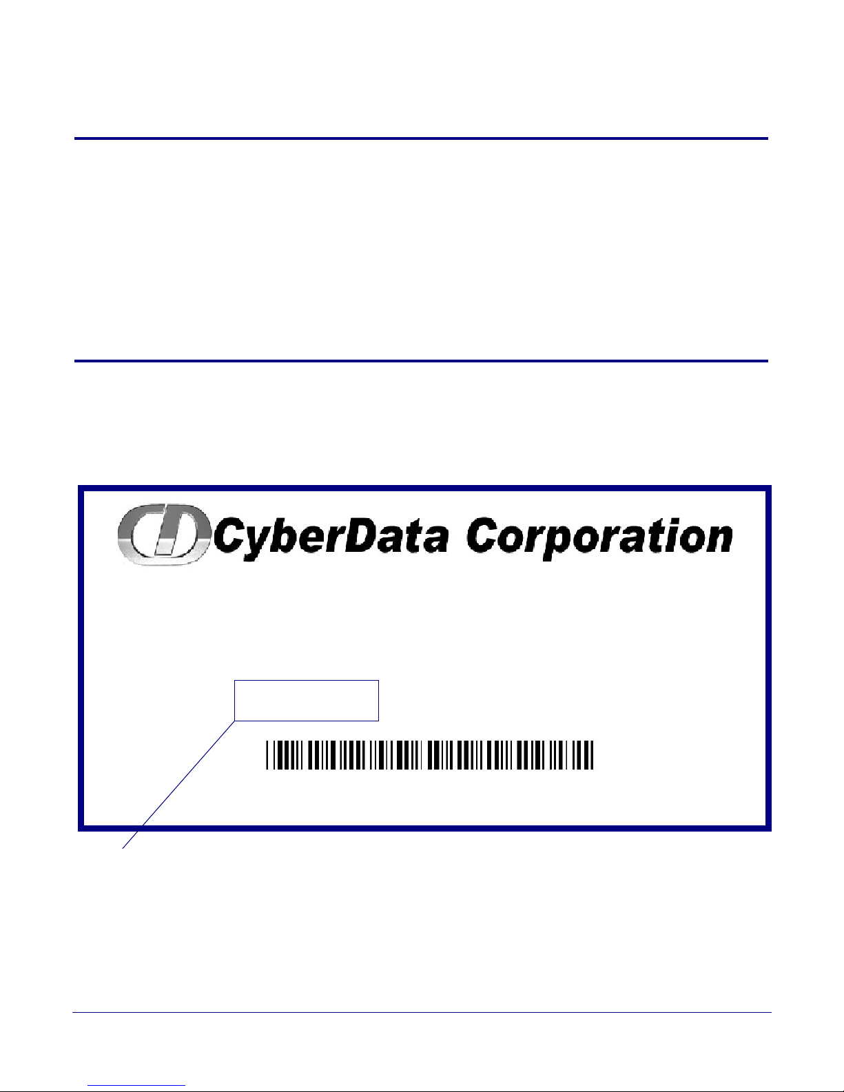
1.1 How to Identify This Product
To identify the VoIP V2 Loudspeaker Amplifier (AC-Powered), look for a model number label
similar to the one shown in
Figure 1-1. The model number on the label should be 011095.
1
Figure 1-1. Model Number Label
Operation s Guide 930360I CyberData Corporation

1.2 Typical System Installation
802.3af Compliant Ethernet Switch
VoIP Phone SIP Server
12 34 56
Loudspeaker Amplifier
High Power PoE Injector in Box
• SIP (RFC 3261) compatible
• Dual-speed ethernet 10/100 Mbps
• Web-based configuration
• Web-based firmware upgradeable
• PoE 802.3at and 802.3af-enabled
•IGMP
• Line-out connector
• DTMF controlled relay with open sense
• Direct speaker drive
• User-uploadable tones
• Simultaneous SIP and Multicast
• Autoprovisioning
•Line-In capability
• Nightringer
• Weather-resistant NEMA enclosure
Figure 1-2 illustrates how the VoIP V2 Loudspeaker Amplifier is normally installed as part of a
public address system.
Figure 1-2. Typical Installation
Product Overview
Typical System Installation
2
1.3 Product Features
Operation s Guide 930360I CyberData Corporation

1.4 Supported Protocols
The Loudspeaker Amplifier supports:
•SIP
•Multicast
• HTTP Web-based configuration
Provides an intuitive user interface for easy system configuration and verification of
Loudspeaker Amplifier operations.
•DHCP Client
Dynamically assigns IP addresses in addition to the option to use static addressing.
•TFTP Client
Facilitates Web-based firmware upgrades of the latest Loudspeaker Amplifier capabilities.
•RTP
• RTP/AVP - Audio Video Profile
•SPEEX
• Audio Encodings
PCMU (G.711 mu-law)
PCMA (G.711 A-law)
Packet Time 20 ms
Product Overview
Supported Protocols
3
1.5 Supported SIP Servers
The following link contains information on how to configure the Loudspeaker Amplifier for the
supported SIP servers:
http://www.cyberdata.net/support/server/index.html
Operation s Guide 930360I CyberData Corporation

1.6 Product Specifications
Table 1. Product Specifications
Category Specification
Ethernet I/F 10/100 Mbps
Power Input PoE 802.3at or 802.3af
Operating Temperature -30 to 55 C (-22 to 131 F)
Protocol SIP RFC 3261
Payload Types G711, SPEEX
Regulatory Compliance FCC Class A, CE
Warranty 2 Years Limited
Dimensions 14” x 10” x 4”
Audio Output 802.3af - up to 10 Watts (default, 50% duty
cycle [one second on and one second off]).
802.3at - up to 22 Watts (default, 50% duty
cycle [one second on and one second off])
Product Overview
Product Specifications
4
Line In:
Input Signal Amplitudes
Input Impedance
Line Out:
Output Signal Amplitudes
Output Level
Total Harmonic Distortion
Output Impedance
Par t Number 011095
2.0 VPP maximum
10k Ohm
2.0 VPP maximum
+2dBm nominal
0.5% maximum
10k Ohm
Operation s Guide 930360I CyberData Corporation
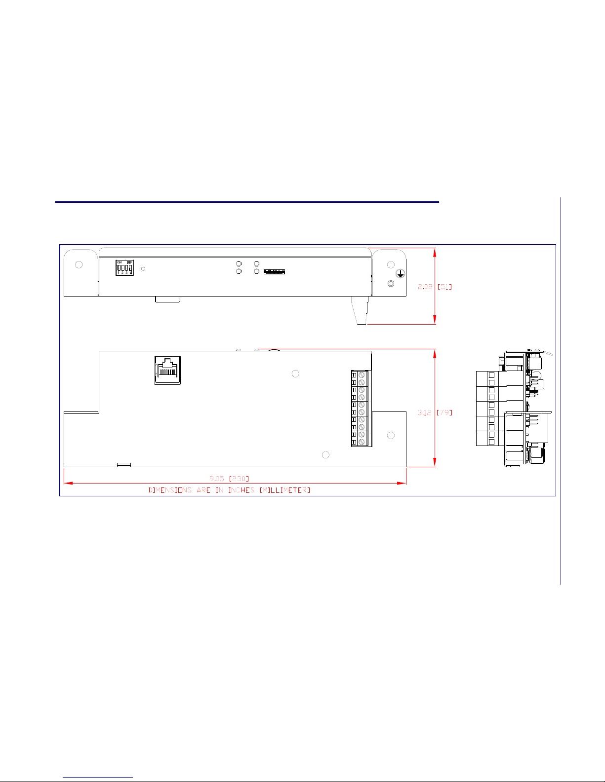
Product Overview
Dimensions
Operations Guide 930360I CyberData Corporation
5
1.7 Dimensions
Figure 1-3. Dimensions
2 Installing the VoIP V2 Loudspeaker
Amplifier
2.1 Parts List
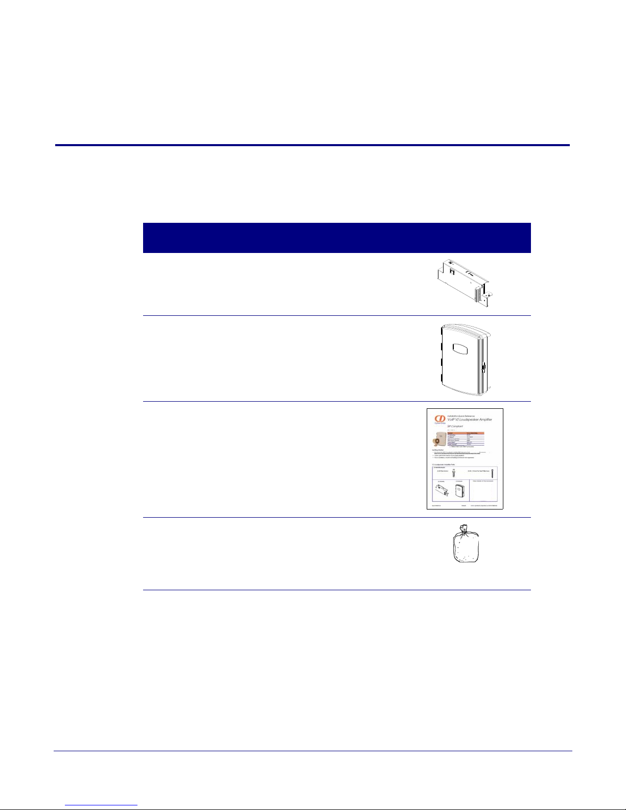
Ta bl e 2-1 illustrates the parts for each Loudspeaker Amplifier and includes a kit for mounting.
Table 2-1. Parts List
6
Quanti
ty
1 Loudspeaker Amplifier Assembly
1 Enclosure
1 Installation Quick Reference Guide
1 Loudspeaker Amplifier Mounting Accessory Kit,
RoHS
(part #071057A) which includes:
(3)Plastic Ribbed Anchors
(3) #6 Sheet Metal Screws
Part Name Illustration
Operation s Guide 930360I CyberData Corporation

2.2 Loudspeaker Amplifier Setup
Set up and configure each Loudspeaker Amplifier before you mount it.
CyberData delivers each Loudspeaker Amplifier with the factory default values indicated in
Table 2-2:
Table 2-2. Factory Default Settings—Default of Netw ork
Parameter Factory Default Setting
IP Addressing DHCP
IP Address
Web Access Username admin
Web Access Password admin
Subnet Mask
Default Gateway
a
a
a
a. Default if there is not a DHCP server present.
Installing the VoIP V2 Loudspeaker Amplifier
10.10.10.10
255.0.0.0
10.0.0.1
7
Loudspeaker Amplifier Setup
Operation s Guide 930360I CyberData Corporation
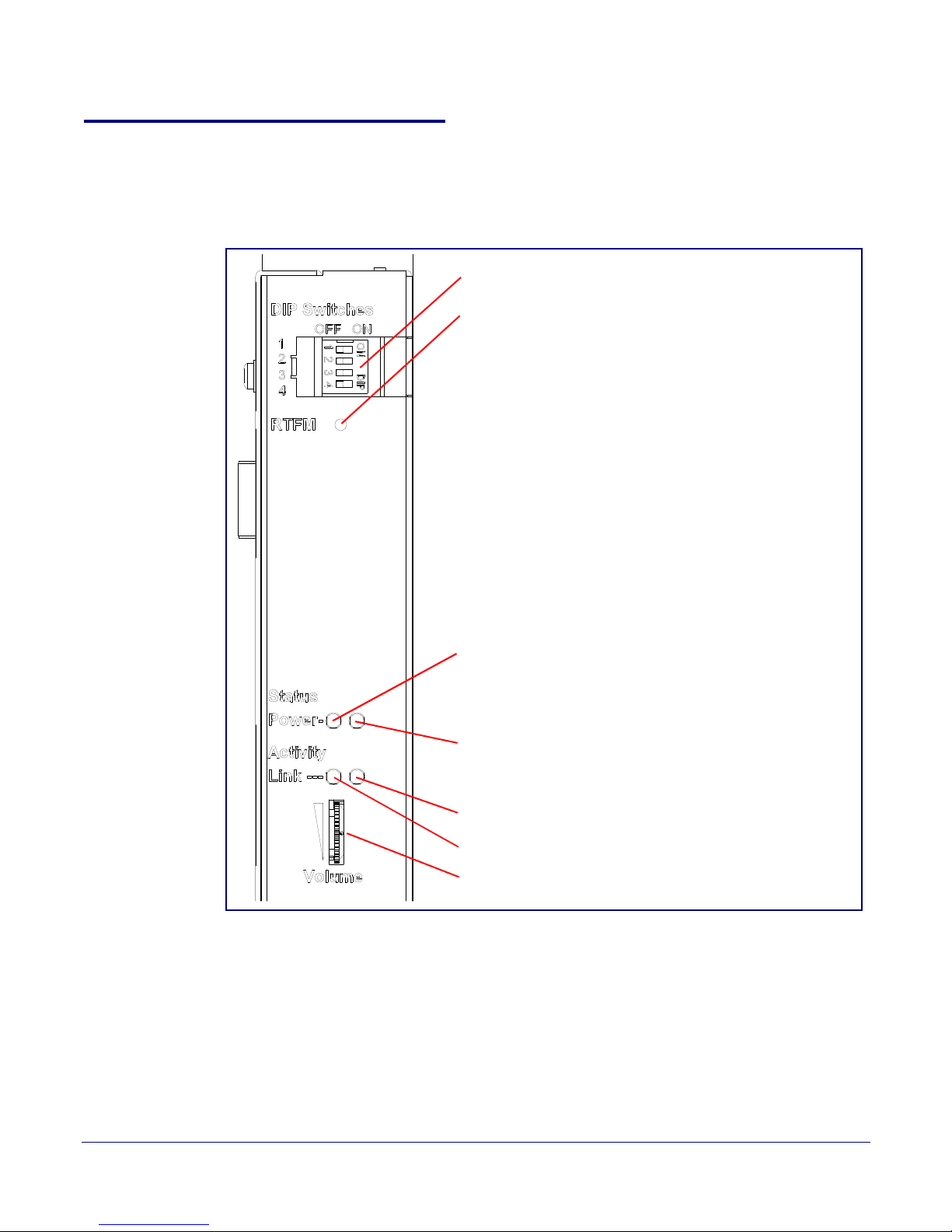
2.2.1 Loudspeaker Amplifier Components
DIP Switches
Speaker Volume
Network Link LED (GREEN/YELLOW)
Status LED (GREEN)
A steady LED confirms that the Loudspeaker Amplifier is operational. The LED will blink during a page when it is online.
Network Activity LED (GREEN)
Power LED (GREEN/BLUE)
The power LED is a steady green in low power mode and
a steady blue during high power mode. The power LED
will only blink either during a boot up or a phone call.
RTFM Switch
To broadcast a Loudspeaker Amplifier’s current IP
address, press and hold the RTFM switch for a couple of
seconds and then release it.
To restore the factory defaults, complete the following
steps:
1. Press and hold the RTFM switch until you hear the
Loudspeaker Amplifier announce the words, “restoring
defaults” and “rebooting”.
2. Release the RTFM switch. The Loudspeaker Amplifier
will be restored to the factory default settings.
Figure 2-4 shows the components of the Loudspeaker Amplifier .
Figure 2-4. Loudspeaker Amplifier Components
Installing the VoIP V2 Loudspeaker Amplifier
Loudspeaker Amplifier Setup
8
Operation s Guide 930360I CyberData Corporation
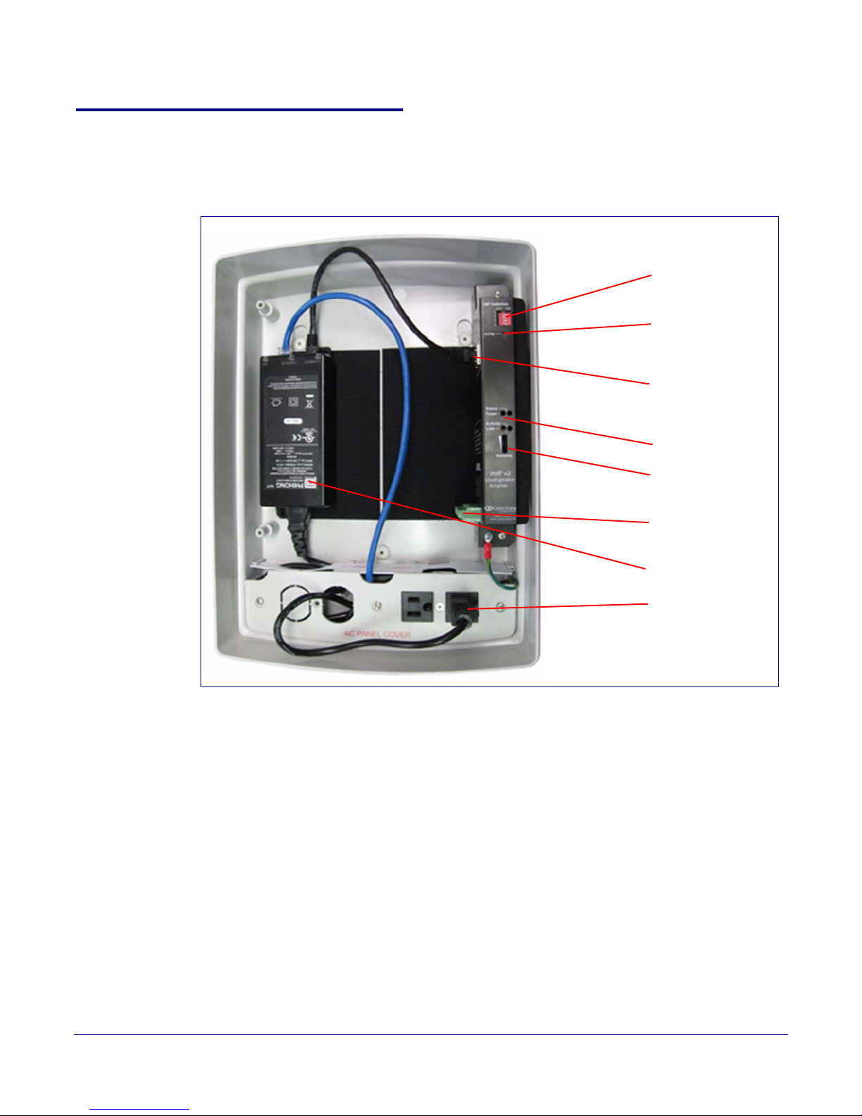
Installing the VoIP V2 Loudspeaker Amplifier
Speaker Connection
Ethernet Connection
DIP Switches
RTFM Switch
Volum e
AC power
Injector
LEDs
2.2.2 Loudspeaker Amplifier NEMA Box Components
Figure 2-5 shows all of the NEMA box components of the loudspeaker amplifier.
Figure 2-5. Loudspeaker Amplifier Components—AC pow ered
9
Loudspeaker Amplifier Setup
Operation s Guide 930360I CyberData Corporation
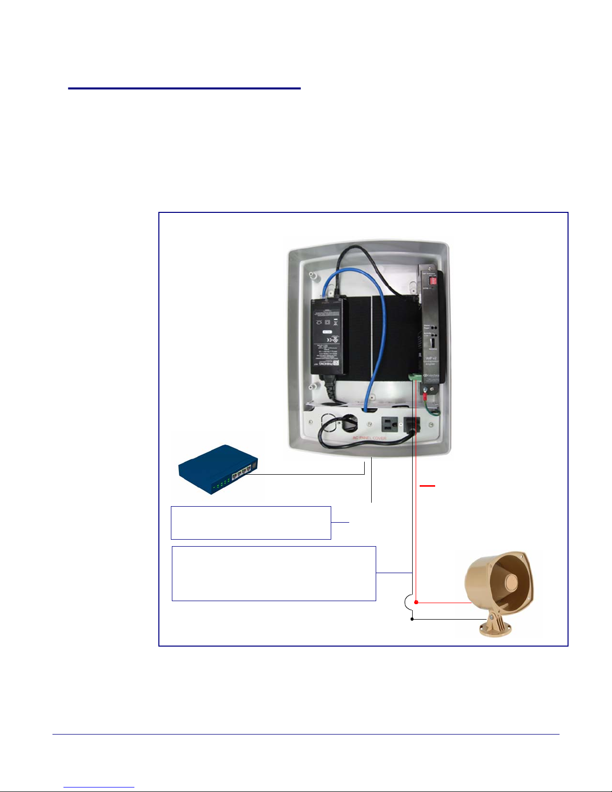
2.2.3 Connecting the Loudspeaker Amplifier
AC Input*
~
+
Standard 1 Speaker Configuration
(802.3af mode)
8 Ohms
16 gauge wire
+
-
Use 16 gauge wire coming out of screw terminals.
Note
: The maximum wire length from the amplifier
to the speaker should not be more than 25 feet.
Cat 5 Ethernet Cable
Non-PoE Ethernet Switch
*Note: This AC connection needs to
be installed by a certified electrician.
2.2.3.1 Using the Amplified Outputs
Figure 2-6 and Figure 2-7 illustrates how to connect the VoIP V2 Loudspeaker Amplifier and use the
amplified outputs in low and high power mode.
Installing the VoIP V2 Loudspeaker Amplifier
Loudspeaker Amplifier Setup
10
Low Power Mode
Figure 2-6. Using the Amplified O utputs—Low Power Mode
Operation s Guide 930360I CyberData Corporation
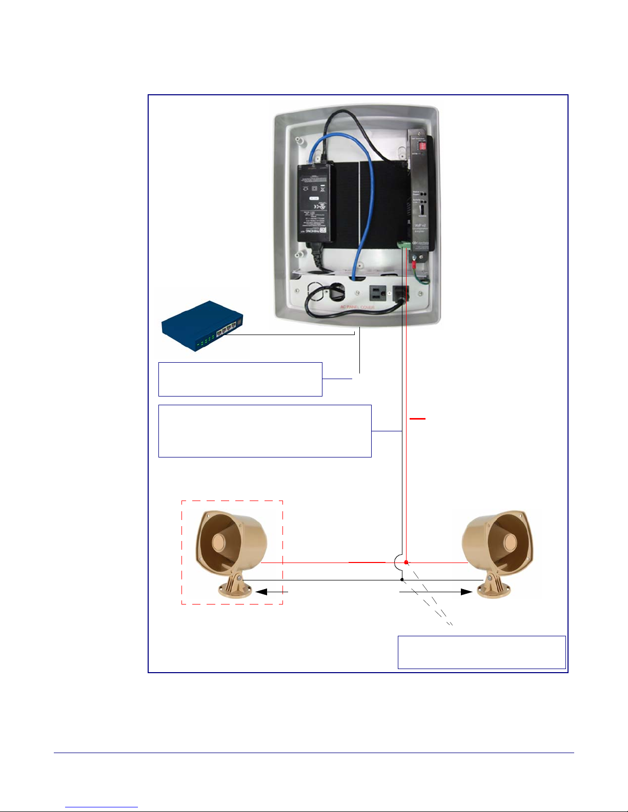
Installing the VoIP V2 Loudspeaker Amplifier
AC Input*
~
Cat 5 Ethernet Cable
Non-PoE Ethernet Switch
2 speakers in parallel (4 Ohm total)
+
Note: Use wire nuts to connect wire
from the speakers to 16 gauge wire.
Twist wire nuts
Optional 2 Speaker Configuration
(802.3at mode)
8 Ohms
Standard 1 Speaker Configuration
(802.3af mode)
8 Ohms
16 gauge wire
25 feet maximum distance
++
--
Use 16 gauge wire coming out of screw terminals.
Note: Make sure that the wire length going to the
wire nuts is kept short (approximately 6 inches).
*Note: This AC connection needs to
be installed by a certified electrician.
Loudspeaker Amplifier Setup
11
High Power Mode
Figure 2-7. Using the Amplified Outputs—High Power Mode
Operation s Guide 930360I CyberData Corporation
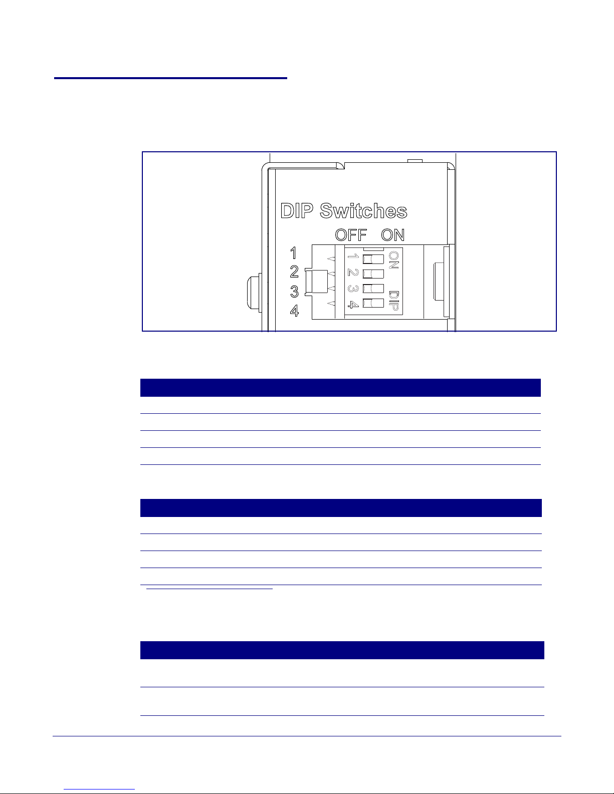
2.2.4 Loudspeaker Amplifier DIP Switches
See Figure 2-8 to identify the DIP Switches.
Figure 2-8. DIP Switches
Installing the VoIP V2 Loudspeaker Amplifier
Loudspeaker Amplifier Setup
12
See Table 2-3 and Table 2-4 for the DIP Switch settings for the revision B (or later) board.
Table 2-3. DIP Switch Settings—Low Power—802.3af Compliant
DIP Switch Setting Description
1 OFF Sets PoE for 802.3af class.
2 N/A Not applicable for power setting.
3 ON Switch mode current set to LOW.
4 OFF Low gain amplifier setting.
Table 2-4. DIP Switch Settings—High Power—802.3at C ompliant (Default)
a
DIP Switch Setting Description
1 ON Sets PoE for 802.3at class.
2 N/A Not applicable for power setting.
3 OFF Switch mode current set to HIGH.
4 ON Force high gain amplifier.
a. If set to high power, the unit will not power ON with 802.3af compliant switch. You must use a power injector
in this mode (CyberData par t number 010867A).
Table 2-5. DIP Switch 2 Settings
DIP Switch Setting Description
2 OFF Manual Vol. The speaker volume is set manually by the analog volume
2 ON Bypass. Bypasses the manual volume control of the analog volume
Operation s Guide 930360I CyberData Corporation
trimmer.
trimmer and uses the web page volume settings.

Installing the VoIP V2 Loudspeaker Amplifier
1-Sense (+)
2-GND
3-Relay COM
4-Relay NO
5-Line-In(+)
6-Line-In(-)
7-Line-Out(+)
8-Line-Out(-)
9-Spkr Out(+)
10-Spkr Out (-)
CLASS II WIRING
See Figure 2-
See Figure 2-
See Figure 2-
See Figure 2-
See Figure 2-14
Amplifier
Amplifier
Alert Strobe
When the Loudspeaker Amplifier is
called from a remote phone, the
relay on the Loudspeaker Amplifier
can be programmed to blink and
drive an Alert Strobe.
Amplifier
When line-in is enabled on
the V2 Amplifier, the audio
received from the line-in
connection will be played
to the speaker(s) and lineout connection as the lowest priority audio.
Line Plug
Loudspeaker Amplifier Setup
2.2.5 VoIP V2 Loudspeaker Amplifier System Installation and Connection
Options
The following figures show the connection options for the VoIP V2 Loudspeaker Amplifier.
Figure 2-9. Loudspeaker Amplifier Connections
Figure 2-10. Sensor Connectio n
13
Operation s Guide 930360I CyberData Corporation
Figure 2-11. Relay or Strobe Alert Connection
Figure 2-12. Line-In Connection
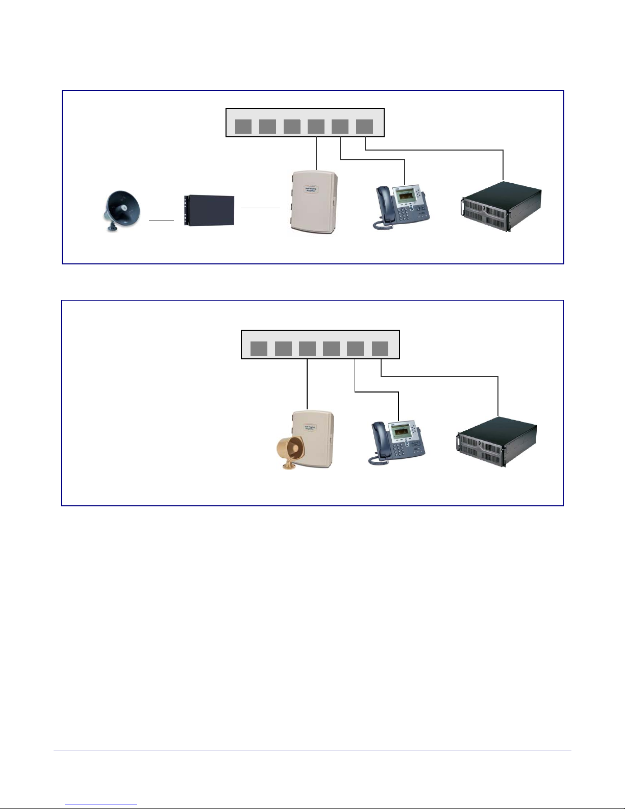
Installing the VoIP V2 Loudspeaker Amplifier
Generic Ethernet Switch
IP Phone IP PBX Server
12 34 56
Existing Loudspeaker
Existing Amplifier
Line-out
Connection
(up to 25 watts)
Loudspeaker Amplifier
VoIP Phone
12 34 56
011068 Loudspeaker
IP PBX Server
802.3af Compliant Ethernet Switch
High Power PoE Switch
(up to 25 watts)
Loudspeaker Amplifier
High Power PoE Injector in Box
Figure 2-13. Line Out Connection
Figure 2-14. Speaker Out Connection
14
Loudspeaker Amplifier Setup
Operation s Guide 930360I CyberData Corporation
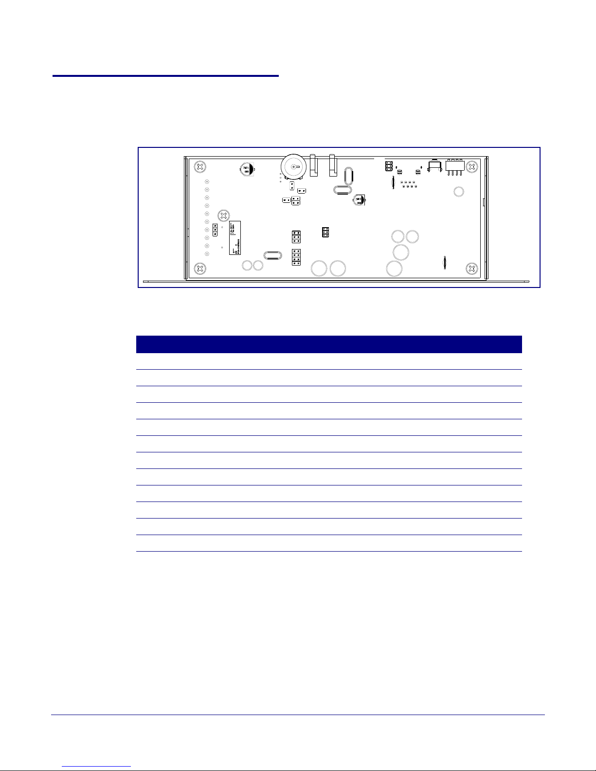
2.2.6 Loudspeaker Amplifier Jumpers
JP5
JP3
JP1
JP6
JP4
J8
JP1
JP2
JP3
J7
JP9
JP8
JP7
JP10
See Figure 2-15 for the jumper locations.
Figure 2-15. Jumper Locations
See Table 2-6 for the jumper descriptions.
Installing the VoIP V2 Loudspeaker Amplifier
Loudspeaker Amplifier Setup
15
Table 2-6. Jumper Descriptions
Jumper Description
JP1 Factory Only—Not Used
JP2 Factory Only—Not Used
JP3 Factory Only—Not Used
JP4 Manual Reset—Not Used
JP5 Watch Dog Timer Enable—Not Used
JP6 Audio Enable—Factory Only
JP7 Factory Only—Not Used
JP8 Factory Only—Not Used
JP9 Factory Only—Not Used
JP10 Relay Connection Option—Wire link in position-A.
J7 JTAG Interference—Factor y Only
J8 Console Port—Factory Only
Operation s Guide 930360I CyberData Corporation
Installing the VoIP V2 Loudspeaker Amplifier
Loudspeaker Amplifier Setup
See Table 2-7 for details about the Loudspeaker Amplifier connections.
Table 2-7. Loudspeaker Amplifier Connections
Connection Connection Details Location
16
Ethernet
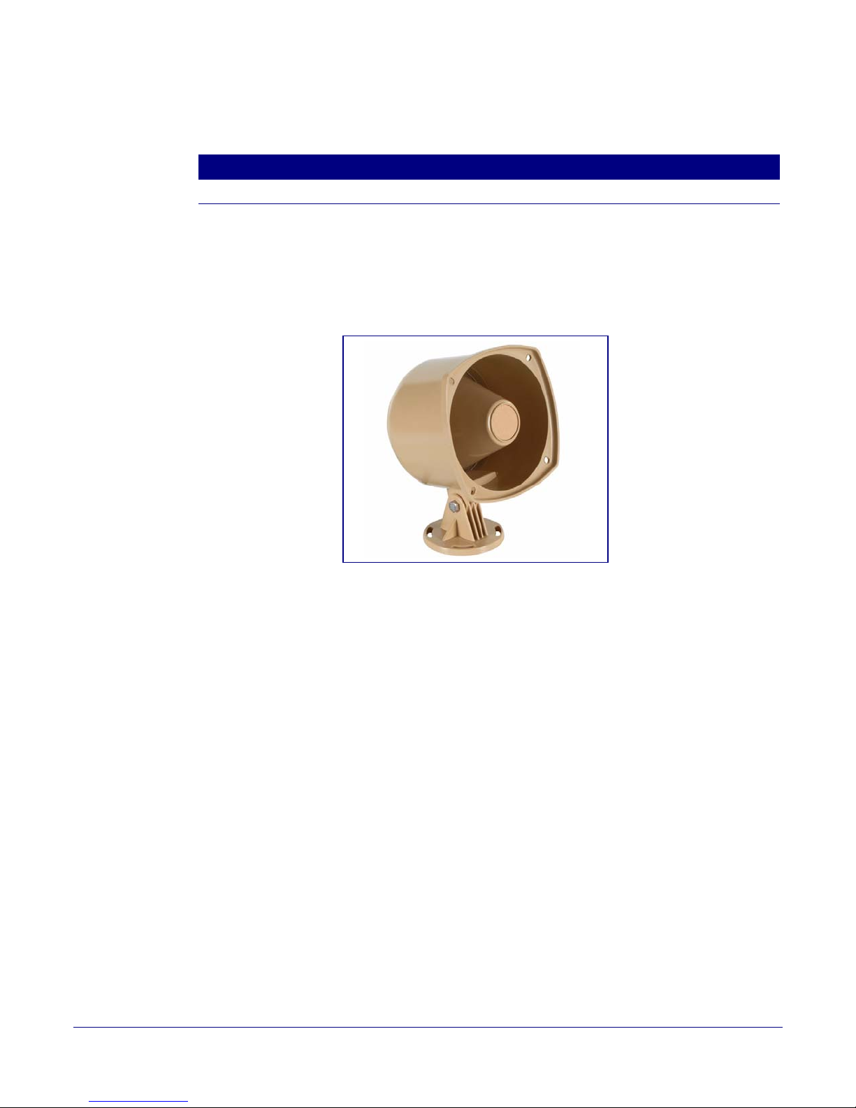
2.2.6.1 Loudspeaker Type
Using the amplified output, the CyberData VoIP V2 Loudspeaker Amplifier supports the 011068
Loudspeaker or equivalent unamplified loudspeaker.
● Use a RJ 45 cable.
Figure 2-16. 011068 Loudspeaker
VoIP V2 Loudspeaker Amplifier
2.2.6.2 Cabling/Wiring
Using the amplified output, you may connect a 011068 loudspeaker or equivalent unamplified
speaker to a Loudspeaker Amplifier with good quality speaker wire that is 16 gauge and limited to
25 feet in length.
Operation s Guide 930360I CyberData Corporation

2.2.7 Confirm Operation
Power LED (blue/green)
Link LED (green/yellow)
Status LED (green)
Activity LED
(green)(yellow)
After connecting the Loudspeaker Amplifier to the ethernet hub, use the LEDs on the Loudspeaker
Amplifier face to confirm that the Loudspeaker Amplifier is operational and linked to the network.
LED Color Function
Power Blue/Green The power LED is illuminated a steady green when the power is on and in
Status Green After supplying power to the Loudspeaker Amplifier, a steady LED confirms
Link Green/Ye l l ow The Link LED is illuminated green for a 10Mb link or yellow/green for a
Activity Green The Activity LED blinks to indicate network traffic.
Installing the VoIP V2 Loudspeaker Amplifier
Loudspeaker Amplifier Setup
Table 2-8. Loudspeaker Amplifier LEDs
low power mode. The power LED is illuminated a steady blue when the
amplifier is in high power mode. The power LED will blink during a boot up or
a phone call.
that the Loudspeaker Amplifier is operational. The status LED will blink
during a page when it is online.
100Mb link when the network link to the Loudspeaker Amplifier is
established.
17
Figure 2-17. Loudspeaker Amplifier LEDs—Power and Link
Figure 2-18. Loudspeaker Amplifier LEDs—Status and Activity
Operation s Guide 930360I CyberData Corporation
 Loading...