

Page 1
The IP Endpoint Company
Installation Quick Reference
PoE VoIP Paging Server
Sip Compliant
010878
Quick Reference 930131C © 2011 CyberData Corporation A LL RIGHTS RESERVED© 2011 CyberDa ta Corporation ALL RIG HTS RESERVED 930131C Quick Reference
Mounting
Contacting Cy berData
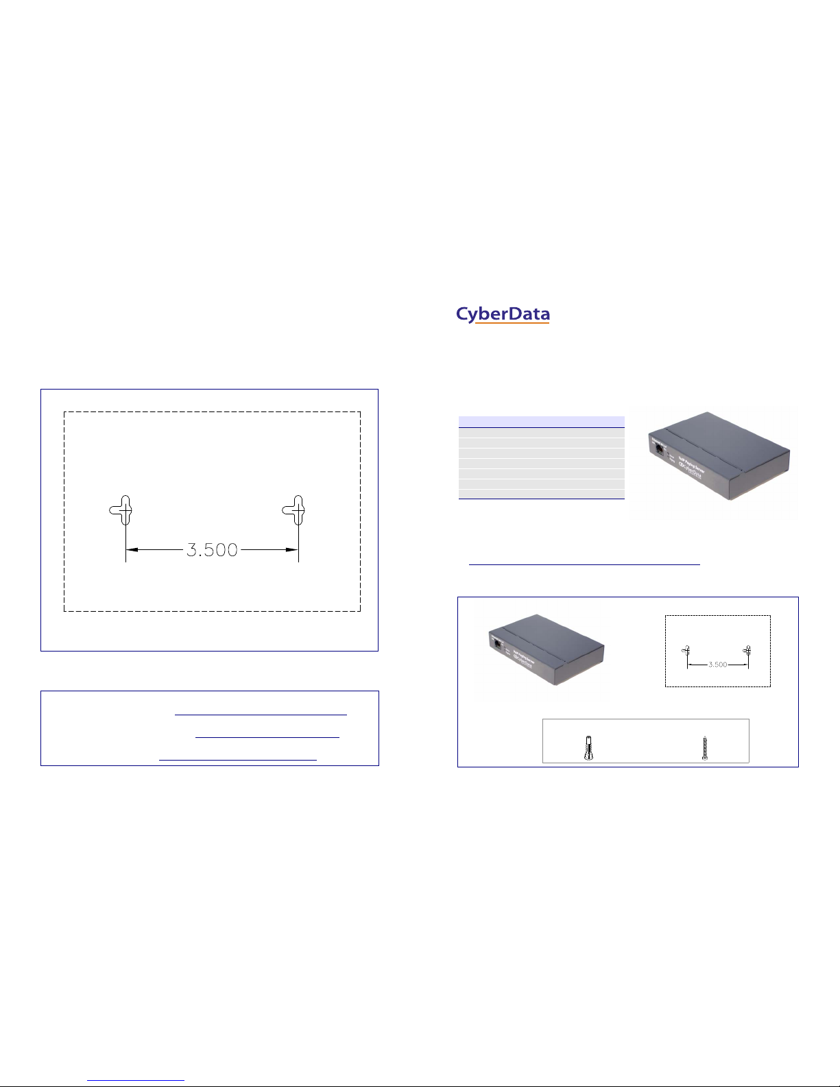
Hole size for Anchor installation: 3/16" (0.1875")
Screws: #6 x 1-1/2" Screw
You have the option to use the following mounting template to mark, and then drill two 3/16" (0.1875”) holes for the
mounting anchors.
To install and mount the Paging Server:
1. Install the mounting anchors in the holes, and position the Paging Server mounting holes over the anchors.
2. Use the two #6 sheet metal screws to secure the Paging Server onto the mounting surface.
Sales: (831) 373-2601 ext. 334
Support: 831-373-2601 ext. 333
Web: http://www.cyberdata.net/support/contactsupportvoip.html
RMA Dept: (831) 373-2601 ext. 136
Email: [email protected]
RMA Status: http://www.cyberdata.net/support/rmastatus.html
Warranty and RMA information is available at the following website:
http://www.cyberdata.net/support/warranty/index.html
Corporate Headquarters
CyberData Corporation
3 Justin Court
Monterey, CA 93940, USA
Phone: 831-373-2601
Fax: 831-373-4193
www.CyberData.net
The VoIP Paging Server enables access to existing paging speakers through a VoIP phone system. This interface uses a
standard paging amplifier, and supports paging to multiple zones from a VoIP phone.
Getting Started
● Be sure that you have received all the parts describ ed in the Parts List section.
● Download th e VoIP Paging Server Operations Guide at:
http://www.cyberdata.net/products/voip/digitalanalog/pagingserver/docs.html
Parts List
Product Specifications
Regulatory Compliance FCC Class A, UL 60950, CE
Power Requirement PoE or +48VDC
LAN Speed 10/100 Mbps
Protocol SiP compliant
Part Number 010878
Dimensions 6.11”L x 4.05”W x 1.15” H
Weight 1.2 lbs.
(2) #6 Mounting Anchors (2) #6 x 1 1/2" Screws
(1) Mounting Template (see the last page)
(1) Mounting Kit
(1) VoIP Paging Server
Page 2
© 2011 CyberD ata Corporation ALL RI GHTS RESERVED 930131C Quick Reference Quick Referenc e 930131C © 2011 Cy berData Corporation AL L RIGHTS RESERVED
Verifying Operations and Settings
To restore these parameters to the factory default
settings:
1. Press and hold the RTFM sw itch for at least
20 seconds.
2. Release the switch. The Status and the
Paging LEDs will go off. The Link and
Activity LEDs will come on for one second
and go off to indicate that the reset process is
starting.
3. During the reset process, the Link LED will
come on and the Activity LED will blink.
After five seconds, the Status and Paging
LEDs come back on.
4. The Paging Server settings are restored to the
factory defaults.
● Green Link light indicates network connectivity
● Orange Link light indicates 100 Mbps baud rate
● Yell o w Link light indicates 10 Mbps baud rate
● Blinking yellow Activity light i ndicates n etwork
activity
● Blinking pale blue Status light indicates the unit
is running
● Dark blue Paging light indicates the unit is
paging
Front View with LEDs
Back View with RTFM Switch
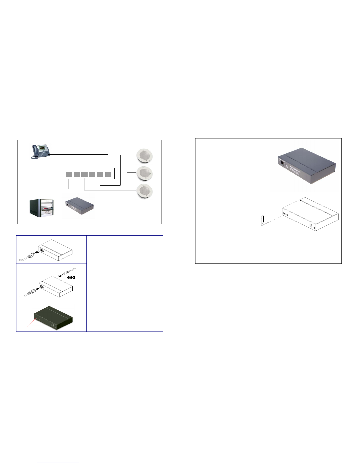
Typical Paging System Setup Using the Paging Server
Setting Up the PoE VoIP Paging Server
VoIP Phone
SIP Server
CyberData
VoIP Speakers
PoE VoIP Paging Server
134526
Generic PoE Switch
48V DC
48V DC
Non PoE (with 48 VDC power supply)
Chassis Ground
Chassis Ground
PoE
To set up the Paging Server, connect the device to
your network:
Poe
● For PoE, plug one end of an 802.3af Ethernet
cable into the Paging Server Ethernet port. Plug
the other end of the Ethernet cable into your
network. See the figure on the left.
Non-Poe
● For Non-PoE, connect the Paging Server to a
48VDC power supply. See the figure on the
left.
Chassis Ground
● If required, connect the earth grounding wire
to the Chassis Ground. See the figure on the
left.
 Loading...