

Page 1
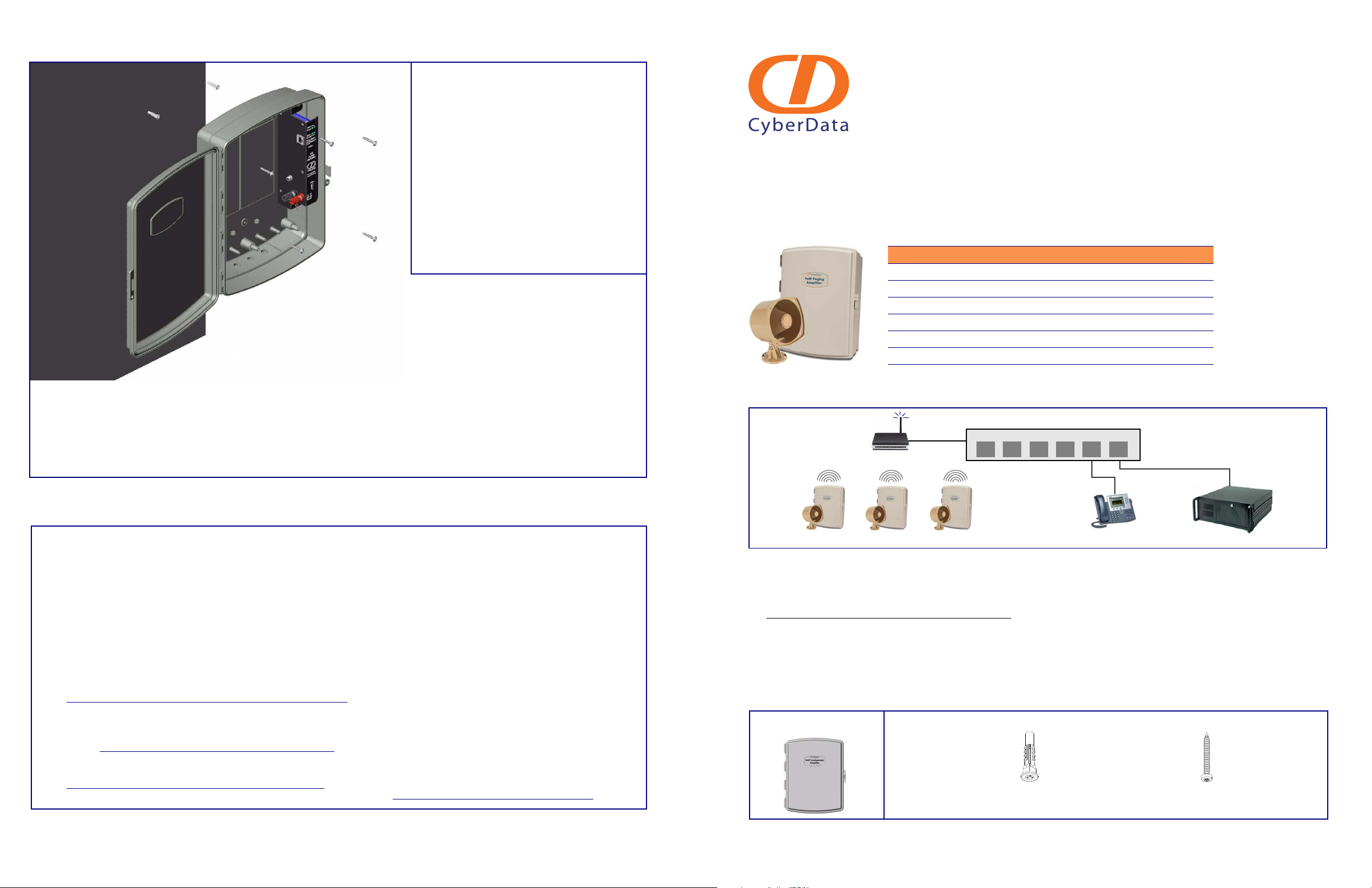
Mounting the Enclosure
Contacting CyberData
To mount the enclosure:
1. Prepare holes for the screws.
2. Plug in the power adapter and use the
blue power light to verify that the power
is on.
3. Plug the Ethernet cable into the
loudspeaker amplifier. The yellow light
verifies the network connection.
4. For wall mounting, use the three
#8 SHEET METAL SCREWS to
secure the speaker.
Warranty
CyberData warrants its product against defects in material or workmanship for
a period of two years from the date of purchase. Should the product fail within
the warranty period, CyberData will repair or replace the product free of
charge. This warranty includes all parts and labor.
Should the product fail out-of-warranty, a flat rate repair charge of one half of
the purchase price of the product will be assessed. Repairs that are in
warranty but are damaged by improper modifications or abuse, will be
charged at the out-of-warranty rate. Products shipped to CyberData, both in
and out-of-warranty, are shipped at the expense of the customer. Shipping
charges for repaired products shipped back to the customer by CyberData,
will be paid by CyberData.
CyberData shall not under any circumstances be liable to any person for any
special, incidental, indirect or consequential damages, including without
limitation, damages resulting from use or malfunction of the products, loss of
profits or revenues or costs of replacement goods, even if CyberData is
informed in advance of the possibility of such damages.
For product service, contact the Returned Materials Authorization (RMA)
department. A product will not be accepted for return without an approved
RMA number. Send the product, in its original package, to: CyberData Corporation, 2555 Garden Road, Monterey, CA 93940, Attention: RMA “your RMA
number”
The most recent warranty information is available at:
Web: http://www.cyberdata.net/support/warranty/index.html
Corporate Headquarters
CyberData Corporation
2555 Garden Road
Monterey, CA 93940, USA
Phone: 831-373-2601
Fax: 831-373-4193
www.CyberData.net
Sales: (831) 373-2601 ext. 334
Support: 831-373-2601 ext. 333
Web: http://www.cyberdata.net/support/contactsupportvoip.html
RMA Dept: (831) 373-2601 ext. 136
Email: [email protected]
RMA Status: http://www.cyberdata.net/support/rmastatus.html
Warranty information is available at:
Web: http://www.cyberdata.net/support/warranty/index.html
Parameter Factory Default Setting
IP Addressing static
IP Address 192.168.3.10
Web Access Username admin
Web Access Password admin
Subnet Mask 255.255.255.0
Default Gateway 192.168.3.1
802.3af Compliant Ethernet Switch
VoIP Loudspeaker Amplifiers VoIP Phone SIP Server
12 3 4 56
Access Point
(1) Enclosure Assembly (1) Wall Mounting Kit
(3) Plastic Ribbed Anchors
(3) #8 Sheet Metal Screws
Installation Quick Reference
VoIP Loudspeaker Amplifier
(Wireless, AC powered)
SiP Compliant
010860
The Loudspeaker Amplifier (Wireless, AC powered) is a Voice-over-IP public address speaker that uses a single cable to
connect to existing LANs.
Typical Loudspeaker Amplifier System Installation
Getting Started
● Download the VoIP Loudspeaker Amplifier (Wireless, AC powered) Operations Guide PDF file at the VoIP Loudspeaker
Amplifier product page at:
http://www.cyberdata.net/support/voip/index.html
● Follow all instructions in the guide.
● Create a plan for the locations of your loudspeaker amplifiers.
● Prior to installation, consult local building and electrical code requirements.
Loudspeaker Amplifier Parts
Quick Reference 930115H © 2009, CyberData Corporation, ALL RIGHTS RESERVED© 2009, CyberData Corporation, ALL RIGHTS RESERVED 930115H Quick Reference
Page 2
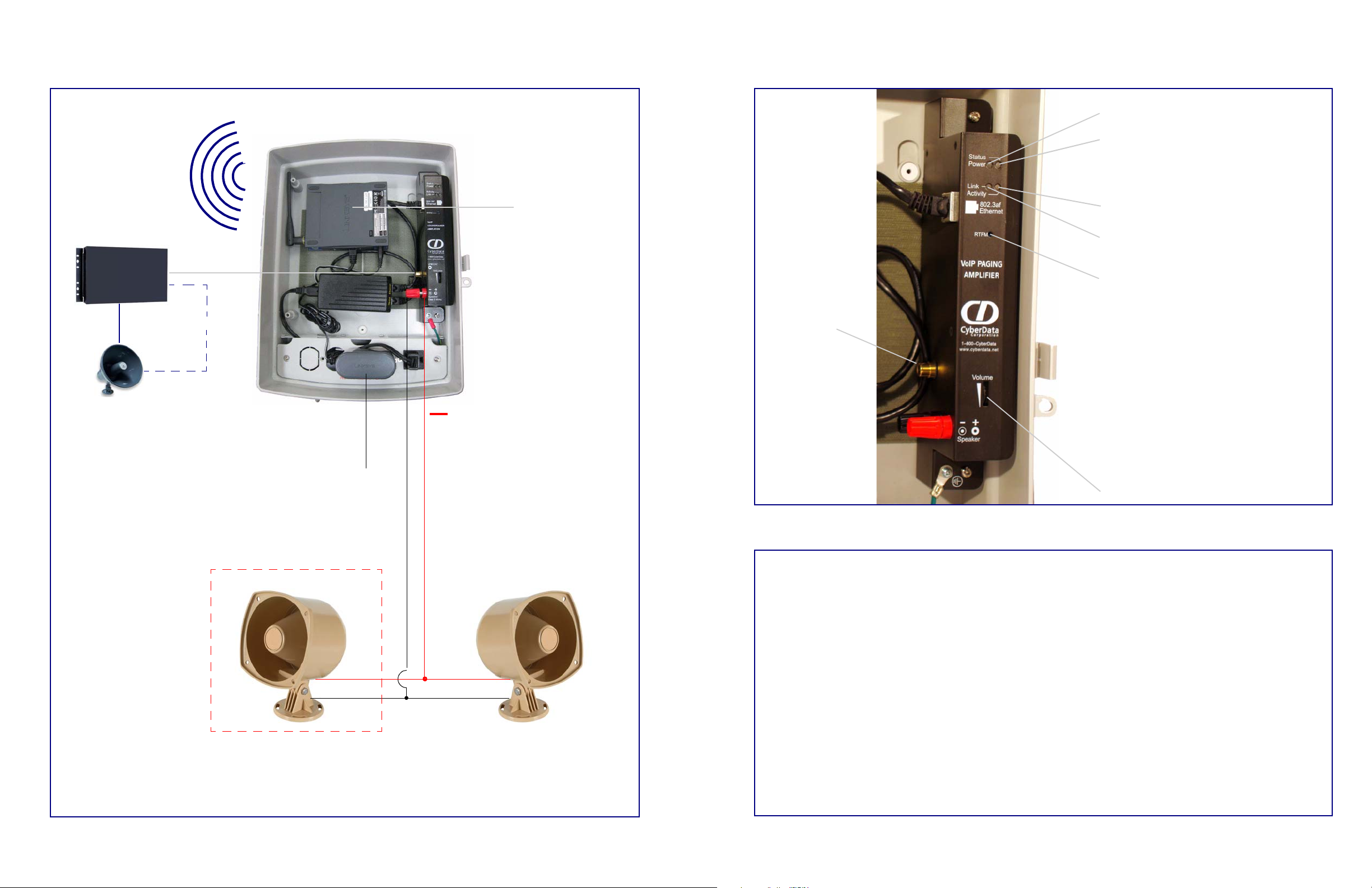
Speaker Volume
RTFM Switch
To broadcast a speaker’s current IP address,
press the RTFM switch on the speaker face.
When the speaker beeps after pressing the
switch for one second, release the switch to
hear the IP address announcement.
Press and hold the RTFM switch for 20
seconds. The speaker will beep after one
second. Continue to hold the switch until the
speaker beeps again after 20 seconds. Then,
release the switch. The speaker settings are
restored to the factory defaults. The speaker
broadcasts the restored default IP address, and
then announces that it is rebooting.
Network Link LED (green/yellow)
Speaker Status LED (green)
A blinking light confirms that the speaker is
operational.
Network Activity LED (green)
Speaker Power LED (blue/green)
Audio Line Out
To set up the wireless bridge for access to the loudspeaker amplifier web configuration access:
1. Set up the host PC ethernet IP address to 192.168.3.xxx where xxx is anything but 226 (default wireless bridge
address) or 010 (default loudspeaker amplifier IP address).
2. Connect an access point to the pc and set the ip address of the access point to 192.168.3.xxx where xxx is not 226,
010, or the ip address of the PC.
3. Set the access point ssid to linksys.
4. Power up the loudspeaker amplifier.
5. Open a web browser and enter the url: http://192.168.3.10. The amplifier speaker configuration page login page
should come up.
6. Follow the configuration instructions in the manual to configure the ip address and parameters for your network.
7. After configuration is complete, use the Bridge Setup Utility supplied with the amplifier to configure the wireless
bridge to the desired network configuration.
Connecting Power to the Loudspeaker Amplifier
8 Ohms
+
8 Ohms
2 speakers in parallel (4 Ohm total)
AC Input*
Optional 2 Speaker Configuration
Standard 1 Speaker Configuration
~
*This AC connection needs to be
installed by a certified electrician.
Wireless Bridge
Amplifier
RCA cable
Existing System
Loudspeaker Amplifier Features
Setting Up the Wireless Bridge
© 2009, CyberData Corporation, ALL RIGHTS RESERVED 930115H Quick Reference Quick Reference 930115H © 2009, CyberData Corporation, ALL RIGHTS RESERVED
 Loading...