

CyberData 10846 Operation Manual
VoIP Paging Gateway
The IP Endpoint Company
Operations Guide
Part #010846
Document Part #930098F
for Firmware Version 3.00
CyberData Corporation
3 Justin Court
Monterey, CA 93940
(831) 373-2601

VoIP Paging Gateway 930098F
Technical Support
The fastest way to get technical support for your VoIP product is to
submit a VoIP Technical Support form at the following website:
http://www.cyberdata.net/support/contactsupportvoip.html
Phone: (831) 373-2601, Ext. 333
Email: support@cyberdata.net
Fax: (831) 373-4193
Company and product information is at www.cyberdata.net.
SiP Compliant 010846
COPYRIGHT NOTICE:
© 2012, CyberData Corporation, ALL RIGHTS RESERVED.
This manual and related materials are the copyrighted property of CyberData Corporation. No part
of this manual or related materials may be reproduced or transmitted, in any form or by any means
(except for internal use by licensed customers), without prior express written permission of
CyberData Corporation. This manual, and the products, software, firmware, and/or hardware
described in this manual are the property of CyberData Corporation, provided under the terms of an
agreement between CyberData Corporation and recipient of this manual, and their use is subject to
that agreement and its terms.
DISCLAIMER: Except as expressly and specifically stated in a written agreement executed by
CyberData Corporation, CyberData Corporation makes no representation or warranty, express or
implied, including any warranty or merchantability or fitness for any purpose, with respect to this
manual or the products, software, firmware, and/or hardware described herein, and CyberData
Corporation assumes no liability for damages or claims resulting from any use of this manual or
such products, software, firmware, and/or hardware. CyberData Corporation reserves the right to
make changes, without notice, to this manual and to any such product, software, firmware, and/or
hardware.
OPEN SOURCE STATEMENT: Certain software components included in CyberData products are
subject to the GNU General Public License (GPL) and Lesser GNU General Public License (LGPL)
“open source” or “free software” licenses. Some of this Open Source Software may be owned by
third parties. Open Source Software is not subject to the terms and conditions of the CyberData
COPYRIGHT NOTICE or software licenses. Your right to copy, modify, and distribute any Open
Source Software is determined by the terms of the GPL, LGPL, or third party, according to who
licenses that software.
Software or firmware developed by CyberData that is unrelated to Open Source Software is
copyrighted by CyberData, subject to the terms of CyberData licenses, and may not be copied,
modified, reverse-engineered, or otherwise altered without explicit written permission from
CyberData Corporation.
TRADEMARK NOTICE: CyberData Corporation and the CyberData Corporation logos are
trademarks of CyberData Corporation. Other product names, trademarks, and service marks may be
the trademarks or registered trademarks of their respective owners.
The IP Endpoint Company
Operations Guide 930098F CyberData Corporation
Important Safety Instructions
GENERAL ALERT
GENERAL ALERT
1. Read these instructions.
2. Keep these instructions.
3. Heed all warnings.
4. Follow all instructions.
5. Do not use this apparatus near water.
6. Clean only with dry cloth.
7. Do not block any ventilation openings. Install in accordance with the manufacturer’s
instructions.
8. Do not install near any heat sources such as radiators, heat registers, stoves, or other apparatus
(including amplifiers) that produce heat.
9. Do not defeat the safety purpose of the polarized or grounding-type plug. A polarized plug has
two blades with one wider than the other. A grounding type plug has two blades and a third
grounding prong. The wide blade or the third prong are provided for your safety. If the
provided plug does not fit into your outlet, consult an electrician for replacement of the obsolete
outlet.
10. Protect the power cord from being walked on or pinched particularly at plugs, convenience
receptacles, and the point where they exit from the apparatus.
11. Only use attachments/accessories specified by the manufacturer.
12. Refer all servicing to qualified service personnel. Servicing is required when the apparatus has
been damaged in any way, such as power-supply cord or plug is damaged, liquid has been
spilled or objects have fallen into the apparatus, the apparatus has been exposed to rain or
moisture, does not operate normally, or has been dropped.
13. Prior to installation, consult local building and electrical code requirements.
14. WARNING: The VoIP Intercom enclosure is not rated for any AC voltages!
Warning
Electrical H az ard: This product should be installed by a licensed electrician
according to al l local electrical and building codes.
Warning
Electrical H az ard: To prevent injury, this apparatus must be se curely attac hed to
the floor/wall in accordance with the installation instructions.
Operations Guide 930098F CyberData Corporation

Pictorial Alert Icons
GENERAL ALERT
Hazard Levels
Danger: Indicates an imminently hazardous situation which, if not avoided, will result in death or
serious injury. This is limited to the most extreme situations.
Warning: Indicates a potentially hazardous situation which, if not avoided, could result in death or
serious injury.
General Alert
This pictoral alert indicates a potentially hazardous situation. This ale rt will be
followed by a haza rd level heading and more specific information about the
hazard.
Ground
This pictora l alert indicates the Earth grounding connection point.
Caution: Indicates a potentially hazardous situation which, if not avoided, could result in minor or
moderate injury. It may also alert users against unsafe practices.
Notice: Indicates a statement of company policy (that is, a safety policy or protection of property).
The safety guidelines for the equipment in this manual do not purport to address all the safety
issues of the equipment. It is the responsibility of the user to establish appropriate safety, ergonomic,
and health practices and determine the applicability of regulatory limitations prior to use. Potential
safety hazards are identified in this manual through the use of words Danger, Warning, and
Caution, the specific hazard type, and pictorial alert icons.
Operations Guide 930098F CyberData Corporation

Revision Information
Revision 930098F, which was released on August 31, 2012 and corresponds to firmware version 3.00,
has the following changes:
•Updates Section 1.2, "Supported Protocols".
Operations Guide 930098F CyberData Corporation

Contents
Chapter 1 Product Overview 1
1.1 Product Features .....................................................................................................................................1
1.2 Supported Protocols ..............................................................................................................................2
1.3 Product Specifications ...........................................................................................................................2
Chapter 2 Setting Up, Configuring, and Using the Paging Gateway 3
2.1 Parts List ..................................................................................................................................................3
2.2 Typical Installation .................................................................................................................................4
2.3 Setting up the VoIP Paging Gateway ..................................................................................................5
2.3.1 Connect to the Power Source ....................................................................................................5
2.3.2 Connect to the Network ............................................................................................................6
2.3.3 Confirm that the VoIP Paging Gateway is Working Properly ..............................................7
2.3.3.1 Confirm Power on, Network Connectivity, and Connection Speed .........................7
2.3.3.2 Verify Network Activity .................................................................................................7
2.3.4 Connect to a Paging Device ......................................................................................................8
2.3.4.1 Connect the VoIP Paging Gateway to a Paging Amplifier .........................................8
2.3.4.2 Connect the VoIP Paging Gateway to a Telephone .....................................................8
2.3.5 Broadcast a test message to all paging zones .........................................................................9
2.3.6 Restore the Factory Default Settings as Required ...............................................................10
2.4 Configuring the VoIP Paging Gateway ............................................................................................11
2.4.1 Gather the Required Configuration Information ................................................................11
2.4.1.1 Static or DHCP Addressing? ........................................................................................11
2.4.1.2 Username and Password for Configuration GUI ..................................................... 11
2.4.1.3 Zone Numbers for Testing Purposes ..........................................................................11
2.4.1.4 SIP Settings ..................................................................................................................... 11
2.4.2 Log in to the Configuration GUI ............................................................................................12
2.4.3 Configure the Network Parameters ......................................................................................14
2.4.4 Change the Default Username and Password .....................................................................16
2.4.5 Broadcast a Test Message to a Specific Paging Zone ..........................................................18
2.4.6 Configure the SiP Parameters .................................................................................................19
2.5 Upgrading the Firmware ...................................................................................................................22
2.6 Rebooting the VoIP Paging Gateway ...............................................................................................24
6
Appendix A: Setting Up a TFTP Server 25
A.1 Set up a TFTP Server ..........................................................................................................................25
A.1.1 In a LINUX Environment ........................................................................................................25
A.1.2 In a Windows Environment ...................................................................................................25
Appendix B: Troubleshooting/Technical Support 26
B.1 Frequently Asked Questions (FAQ) ..................................................................................................26
B.2 Documentation .....................................................................................................................................26
B.3 Contact Information ............................................................................................................................27
B.4 Warranty ...............................................................................................................................................28
B.4.1 Warranty & RMA Returns within the United States ...........................................................28
B.4.2 Warranty & RMA Returns Outside of the United States ....................................................28
B.4.3 Spare in the Air Policy .............................................................................................................28
B.4.4 Return and Restocking Policy .................................................................................................29
B.4.5 Warranty and RMA Returns Page ..........................................................................................29
Index 30
Operations Guide 930098F CyberData Corporation

1 Product Overview
The VoIP Paging Gateway enables access to existing paging speakers through a VoIP phone system.
This interface uses a standard paging amplifier, and supports paging to multiple zones from a VoIP
phone.
1
1.1 Product Features
•SIP compliancy
• Dual speeds of 10Mbps and 100 Mbps
• Multi-zone paging for up to 99 Zones
• Web-based firmware upgrades
•PoE enabled
• Connector for optional external power supply
Operations Guide 930098F CyberData Corporation

1.2 Supported Protocols
•Asterisk™ SIP server
• Offers Open Source benefits with the rich and flexible feature set of a large, proprietary PBX
system.
• HTTP Web-based configuration
• Provides an intuitive GUI for easy system configuration and verification of gateways
operations.
•DHCP Client
• Dynamically assigns IP addresses in addition to the option to use static addressing.
•TFTP Client
• Facilitates Web-based firmware upgrades of the latest speaker capabilities.
•Audio Codec
• G.711 U-law
• Packet size: 20 ms
• DTMF detection/generation
• Echo cancellation
2
1.3 Product Specifications
Specifications
Regulatory Compliance FCC Class A, UL 60950, CE
Power Requirement PoE or 48V DC
Connection Speed 10/100 Mbps
Protocol SiP compliant
Part Number 010846
Dimensions 6.11”L x 4.05”W x 1.15” H
Weight 1.2 pounds
Operations Guide 930098F CyberData Corporation
2 Setting Up, Configuring, and Using the Paging Gateway
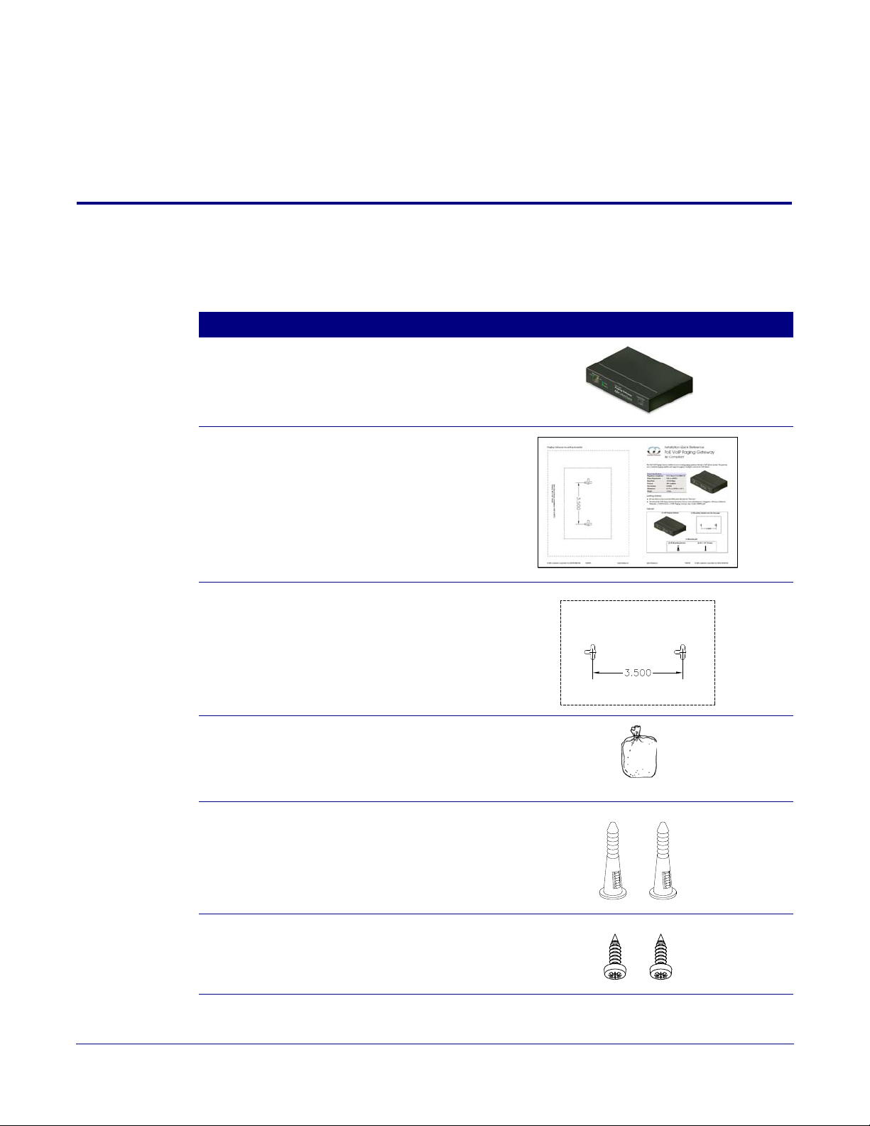
2.1 Parts List
The packaging for the VoIP Paging Gateway includes the parts shown in Ta bl e 2-1.
Table 2-1. Parts List
Quantity Part Name Illustration
1 VoIP Paging Gateway
1 Installation Quick Reference Guide
3
1 Mounting Template (located on the last
page of the Installation Quick
Reference)
1 Mounting Kit (part #070057A)
which includes:
(2) #4-6 x 7/8" Mounting Anchors
(2) #4 x 1-1/4" Round Phillips Wood
Screws
2 #4-6 x 7/8" Mounting Anchors
2 #4 x 1-1/4" Round Phillips Wood
Screws
Operations Guide 930098F CyberData Corporation
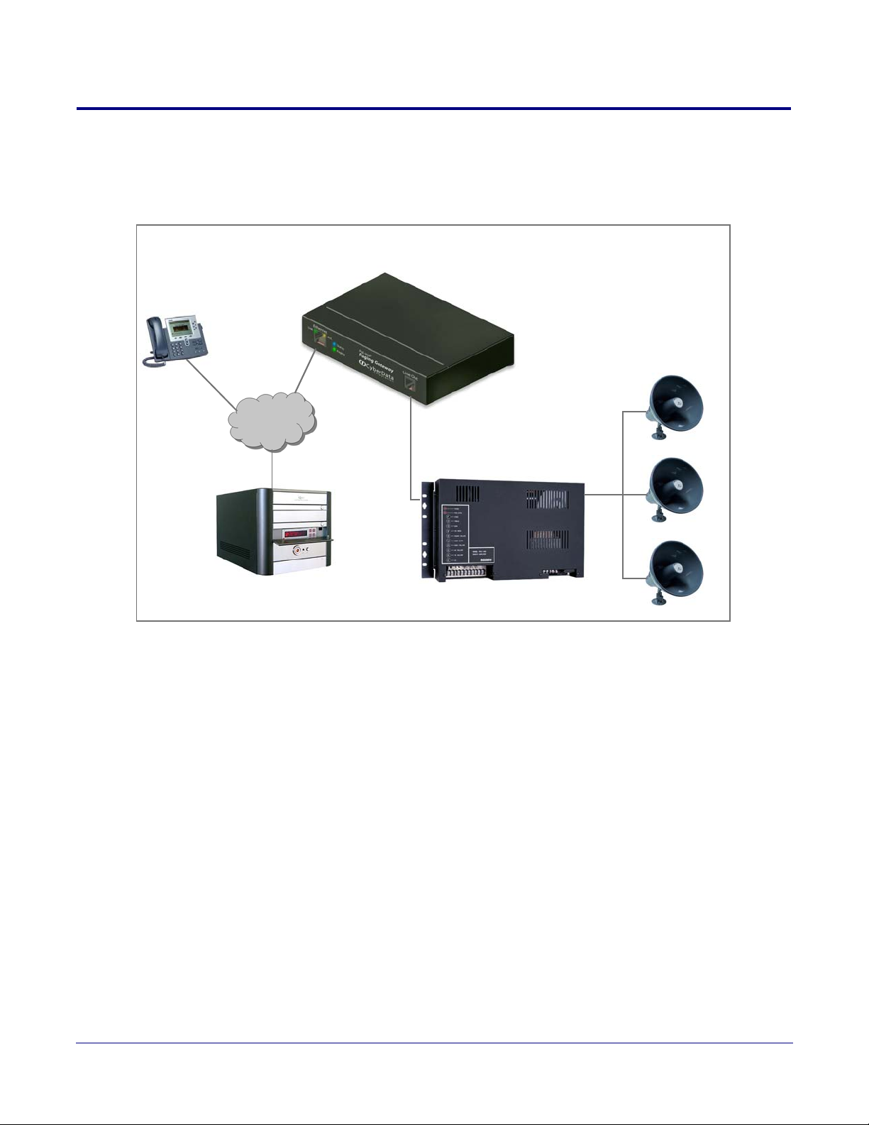
2.2 Typical Installation
Paging Amplifier
VoIP Phone
IP PBX
PoE VoIP Paging Gateway
Paging Speakers
FXO
FXS
Figure 2-1 illustrates how the VoIP Paging Gateway is normally installed as part of a paging system.
Figure 2-1. Typical Installation
4
Complete the following steps after installation:
1. Call to make a page. The VoIP Paging Gateway generates a tone over the phone.
2. When you hear the tone, enter the two-digit code for the zone that you want to page.
• The VoIP Paging Gateway sends the code to the paging amplifier.
• When the paging amp acknowledges the code, the VoIP Paging Gateway generates another tone
to the phone.
3. When you hear the tone, you can begin paging.
Operations Guide 930098F CyberData Corporation
2.3 Setting up the VoIP Paging Gateway
48V DC
Chassis
ground
Before you set up the VoIP Paging Gateway, be sure that you have received all the parts described in
Section 2.1, "Parts List".
To set up the VoIP Paging Gateway, see the following sections:
• Section 2.3.1, "Connect to the Power Source"
• Section 2.3.2, "Connect to the Network"
• Section 2.3.3, "Confirm that the VoIP Paging Gateway is Working Properly"
• Section 2.3.3.1, "Confirm Power on, Network Connectivity, and Connection Speed"
• Section 2.3.3.2, "Verify Network Activity"
• Section 2.3.4, "Connect to a Paging Device"
• Section 2.3.4.1, "Connect the VoIP Paging Gateway to a Paging Amplifier"
• Section 2.3.4.2, "Connect the VoIP Paging Gateway to a Telephone"
• Section 2.3.5, "Broadcast a test message to all paging zones"
• Section 2.3.6, "Restore the Factory Default Settings as Required"
5
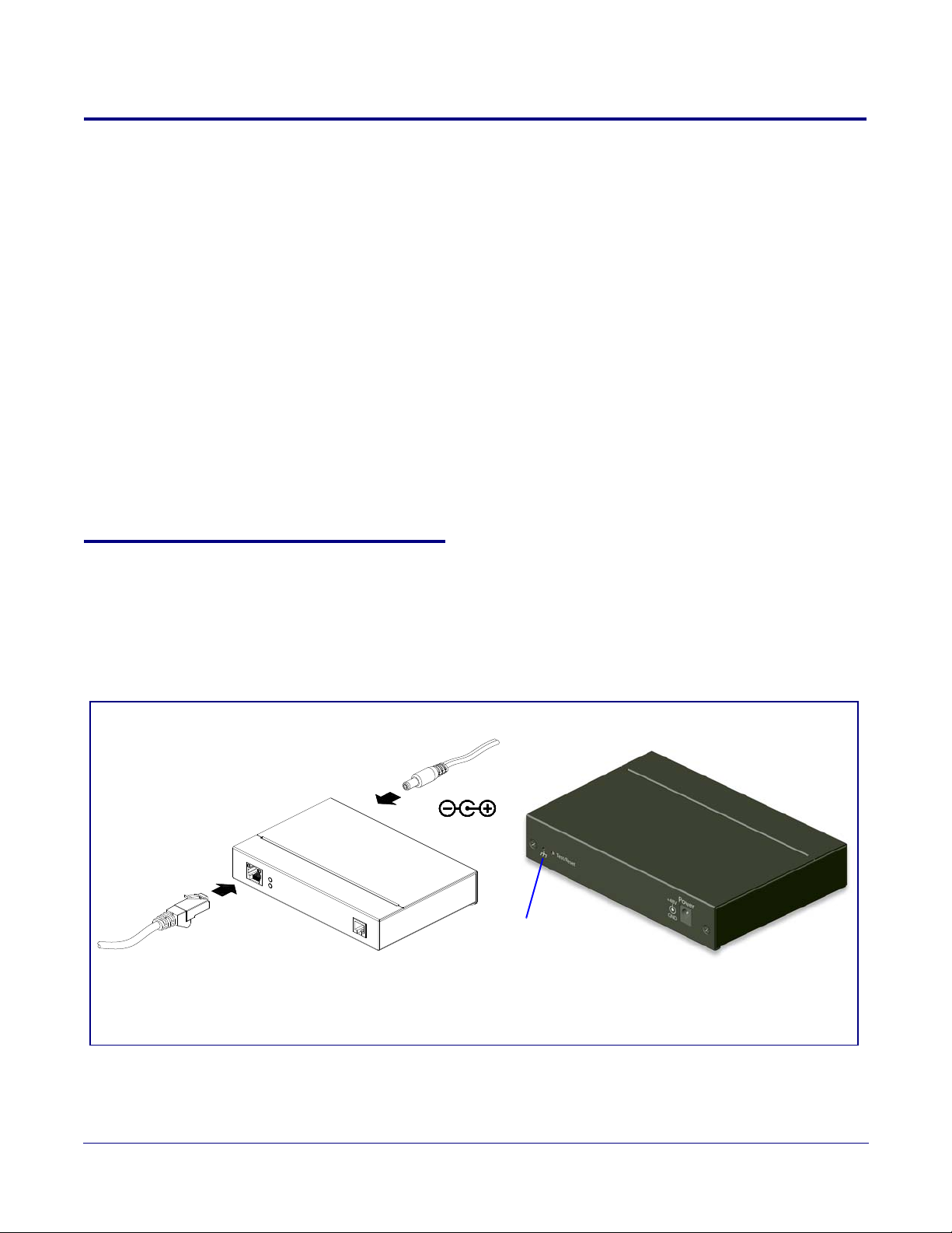
2.3.1 Connect to the Power Source
To use PoE, plug a Cat 5 Ethernet cable from the VoIP Paging Gateway Ethernet port to your
network. As an alternative to PoE, you can plug one end of a +48V DC power supply into the Paging
Gateway, and plug the other end into a receptacle. Connect the earth grounding wire to the chassis
ground on the back of the unit.
Figure 2-2. Connecting to the Power Source
Operations Guide 930098F CyberData Corporation
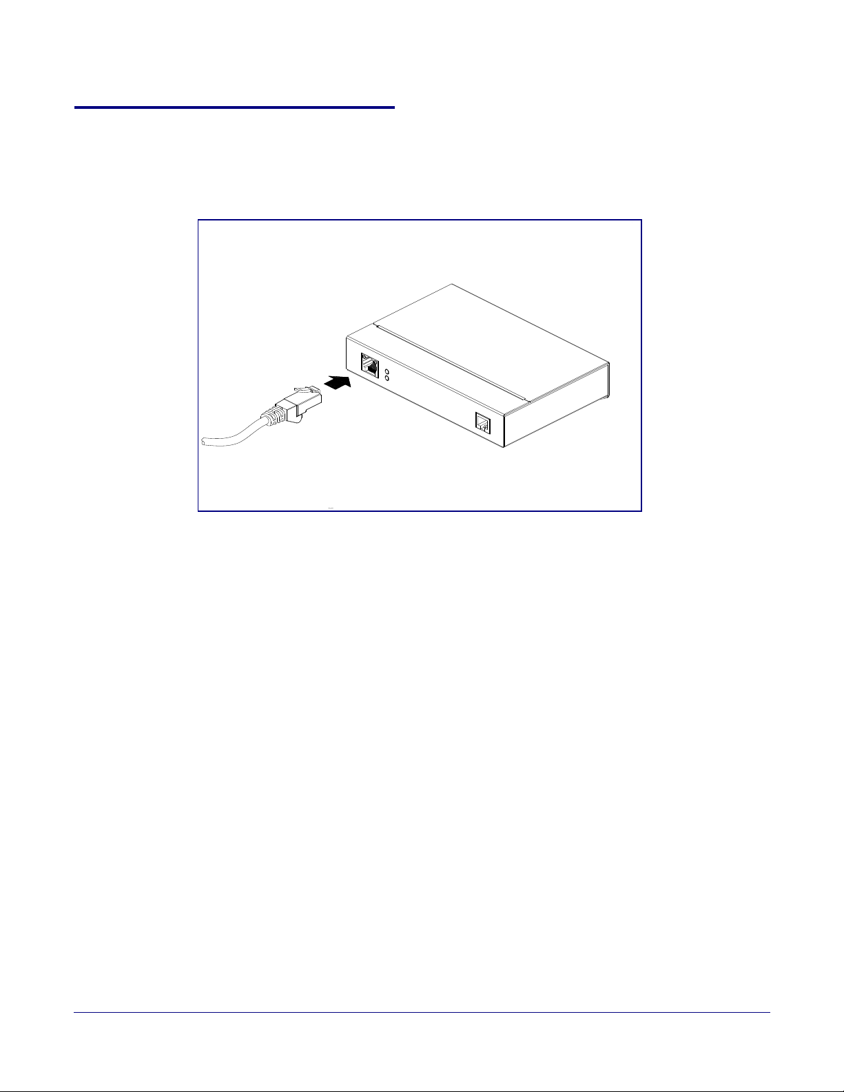
2.3.2 Connect to the Network
48V DC
Plug one end of a standard Ethernet cable into the Paging Gateway Ethernet port. Plug the other
end into your network.
Figure 2-3. Connecting to the Network
6
Operations Guide 930098F CyberData Corporation
 Loading...