

CyberData 011446 Operation Manual
The IP Endpoint Company
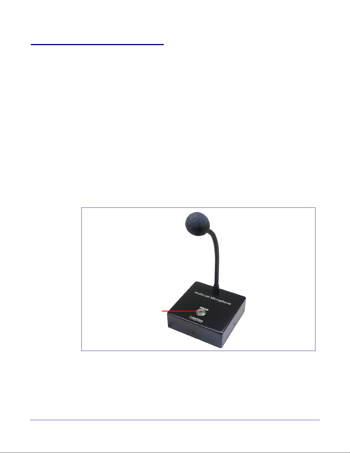
Multicast VoIP Microphone
Operations Guide
Part #011446
Document Part #931431A
for Firmware Version 1.0.0
CyberData Corporation
3 Justin Court
Monterey, CA 93940
(831) 373-2601

Multicast VoIP Microphone Operations Guide 931431A
Technical Support
The fastest way to get technical support for your VoIP product is to
submit a VoIP Technical Support form at the following website:
http://support.cyberdata.net/
Phone: (831) 373-2601, Ext. 333
Email: support@cyberdata.net
Fax: (831) 373-4193
Company and product information is at www.cyberdata.net.
The IP Endpoint Company
Part # 011446
COPYRIGHT NOTICE:
© 2017, CyberData Corporation, ALL RIGHTS RESERVED.
This manual and related materials are the copyrighted property of CyberData Corporation. No part of
this manual or related materials may be reproduced or transmitted, in any form or by any means
(except for internal use by licensed customers), without prior express written permission of
CyberData Corporation. This manual, and the products, software, firmware, and/or hardware
described in this manual are the property of CyberData Corporation, provided under the terms of an
agreement between CyberData Corporation and recipient of this manual, and their use is subject to
that agreement and its terms.
DISCLAIMER: Except as expressly and specifically stated in a written agreement executed by
CyberData Corporation, CyberData Corporation makes no representation or warranty, express or
implied, including any warranty or merchantability or fitness for any purpose, with respect to this
manual or the products, software, firmware, and/or hardware described herein, and CyberData
Corporation assumes no liability for damages or claims resulting from any use of this manual or such
products, software, firmware, and/or hardware. CyberData Corporation reserves the right to make
changes, without notice, to this manual and to any such product, software, firmware, and/or
hardware.
OPEN SOURCE STATEMENT: Certain software components included in CyberData products are
subject to the GNU General Public License (GPL) and Lesser GNU General Public License (LGPL)
“open source” or “free software” licenses. Some of this Open Source Software may be owned by third
parties. Open Source Software is not subject to the terms and conditions of the CyberData
COPYRIGHT NOTICE or software licenses. Your right to copy, modify, and distribute any Open
Source Software is determined by the terms of the GPL, LGPL, or third party, according to who
licenses that software.
CyberData Corporation 931431A Operations Guide
Software or firmware developed by CyberData that is unrelated to Open Source Software is
copyrighted by CyberData, subject to the terms of CyberData licenses, and may not be copied,
modified, reverse-engineered, or otherwise altered without explicit written permission from
CyberData Corporation.
TRADEMARK NOTICE: CyberData Corporation and the CyberData Corporation logos are
trademarks of CyberData Corporation. Other product names, trademarks, and service marks may be
the trademarks or registered trademarks of their respective owners.

Revision Information
Revision 931431A, which corresponds to firmware version 1.0.0, was released on October 9, 2017,
and has the following changes:
Browsers Supported
The following browsers have been tested against firmware version 1.0.0:
• Chrome (version 570.02987.98)
• Firefox: (version 55.0.2)
• Internet Explorer (version 11.0.9600.18314)
Operations Guide 931431A CyberData Corporation
Important Safety Instructions
GENERAL ALERT
GENERAL ALERT
GENERAL ALERT
1. Read these instructions.
2. Keep these instructions.
3. Heed all warnings.
4. Follow all instructions.
5. Do not use this apparatus near water.
6. Clean only with dry cloth.
7. Do not block any ventilation openings. Install in accordance with the manufacturer’s instructions.
8. Do not install near any heat sources such as radiators, heat registers, stoves, or other apparatus
(including amplifiers) that produce heat.
9. Do not defeat the safety purpose of the polarized or grounding-type plug. A polarized plug has
two blades with one wider than the other. A grounding type plug has two blades and a third
grounding prong. The wide blade or the third prong are provided for your safety. If the provided
plug does not fit into your outlet, consult an electrician for replacement of the obsolete outlet.
10. Protect the power cord from being walked on or pinched particularly at plugs, convenience
receptacles, and the point where they exit from the apparatus.
11. Only use attachments/accessories specified by the manufacturer.
12. Refer all servicing to qualified service personnel. Servicing is required when the apparatus has
been damaged in any way, such as power-supply cord or plug is damaged, liquid has been
spilled or objects have fallen into the apparatus, the apparatus has been exposed to rain or
moisture, does not operate normally, or has been dropped.
13. Prior to installation, consult local building and electrical code requirements.
14. WARNING: The Multicast VoIP Microphone enclosure is not rated for any AC voltages!
Warn in g
Electrical Hazard: This product should be installed by a licensed electrician
according to all local electrical and building codes.
Warn in g
Electrical Hazard: To prevent injury, this apparatus must be securely attached to
the floor/wall in accordance with the installation instructions.
Warn in g
The PoE connector is intended for intra-building connections only and does not
route to the outside plant.
CyberData Corporation 931431A Operations Guide
Pictorial Alert Icons
GENERAL ALERT
Hazard Levels
Danger: Indicates an imminently hazardous situation which, if not avoided, will result in death or
serious injury. This is limited to the most extreme situations.
Warning: Indicates a potentially hazardous situation which, if not avoided, could result in death or
serious injury.
General Alert
This pictorial alert indicates a potentially hazardous situation. This alert will be
followed by a hazard level heading and more specific information about the
hazard.
Ground
This pictorial alert indicates the Earth grounding connection point.
Caution: Indicates a potentially hazardous situation which, if not avoided, could result in minor or
moderate injury. It may also alert users against unsafe practices.
Notice: Indicates a statement of company policy (that is, a safety policy or protection of property).
The safety guidelines for the equipment in this manual do not purport to address all the safety issues
of the equipment. It is the responsibility of the user to establish appropriate safety, ergonomic, and
health practices and determine the applicability of regulatory limitations prior to use. Potential safety
hazards are identified in this manual through the use of words Danger, Warning, and Caution, the
specific hazard type, and pictorial alert icons.
CyberData Corporation 931431A Operations Guide

Abbreviations and Terms
Abbreviation or Term Definition
A-law A standard companding algorithm, used in European digital
communications systems to optimize, i.e., modify, the dynamic range of an
analog signal for digitizing.
AVP Audio Video Profile
Cat 5 TIA/EIA-568-B Category 5
DHCP Dynamic Host Configuration Protocol
LAN Local Area Network
LED Light Emitting Diode
Mbps Megabits per Second.
NTP Network Time Protocol
PBX Private Branch Exchange
PoE Power over Ethernet (as per IEEE 802.3af standard)
RTFM Reset Test Function Management
SIP Session Initiated Protocol
u-law A companding algorithm, primarily used in the digital telecommunication
UC Unified Communications
VoIP Voice over Internet Protocol
CyberData Corporation 931431A Operations Guide

Contents
Chapter 1 Product Overview 1
1.1 How to Identify This Product .....................................................................................................1
1.2 Typical System Installation .......................................................................................................2
1.3 Product Features ......................................................................................................................3
1.4 Supported Protocols .................................................................................................................3
1.5 Specifications ...........................................................................................................................4
Chapter 2 Installing the Multicast VoIP Microphone 5
2.1 Parts List ..................................................................................................................................5
i
2.1.1 Multicast VoIP Microphone Connectors .........................................................................6
2.1.2 Activity and Link LEDs ...................................................................................................8
2.1.3 Restoring the Factory Default Settings ...........................................................................9
2.1.4 Call Button and the Call Button LED ............................................................................10
2.2.1 Factory Default Settings ...............................................................................................11
2.2.2 Multicast VoIP Microphone Web Page Navigation .......................................................12
2.2.3 Using the Toggle Help Button .......................................................................................13
2.2.4 Log in to the Configuration Home Page .......................................................................15
2.2.5 Configure the Device ....................................................................................................18
2.2.6 Configure the Network Parameters .............................................................................24
2.2.7 Configure the Event Parameters ..................................................................................27
2.2.8 Configure the Autoprovisioning Parameters .................................................................31
2.2.9 Downloading the Firmware ...........................................................................................43
2.2.10 Reboot the Device ......................................................................................................45
2.3.1 Command Interface Post Commands ..........................................................................46
Appendix A Mounting the Multicast VoIP Microphone 47
A.1 Mount the Multicast VoIP Microphone ....................................................................................47
Appendix B Troubleshooting/Technical Support 50
B.1 Frequently Asked Questions (FAQ) ........................................................................................50
B.2 Documentation .......................................................................................................................50
B.3 Contact Information ................................................................................................................51
B.4 Warranty and RMA Information ..............................................................................................51
Index 52
Operations Guide 931431A CyberData Corporation
1 Product Overview
MULTICAST VOIP MICROPHONE
011446A / 021108K
www.cyberdata.net
V1.0.0
00:20:F7:03:83:CA
446000001
Model number
Serial number begins with 446
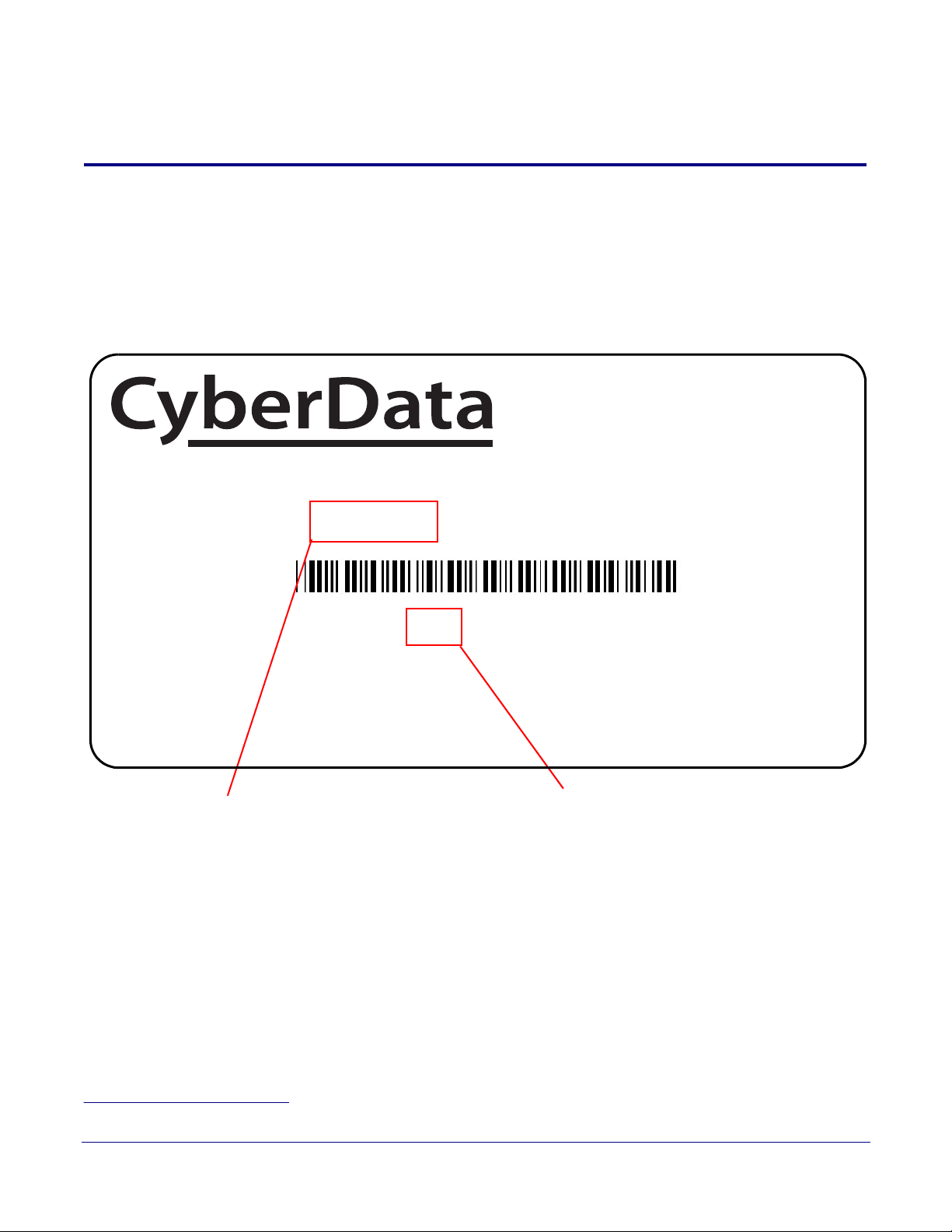
1.1 How to Identify This Product
To identify the Multicast VoIP Microphone, look for a model number label similar to the one shown in
Figure 1-1. Confirm the following:
• The model number on the label should be 011446.
• The serial number on the label should begin with 446.
1
Figure 1-1. Model Number Label
1
1. This figure is just an example. The information on the labels may be different.
Operations Guide 931431A CyberData Corporation
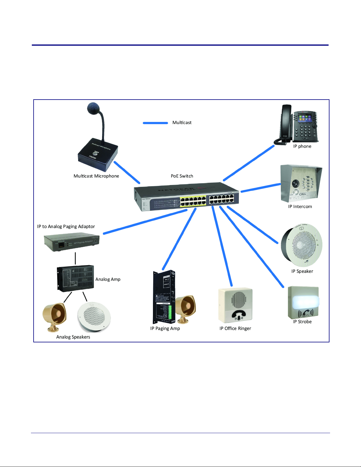
1.2 Typical System Installation
The following figures illustrate how the Multicast VoIP Microphone can be installed as part of a VoIP
phone system.
Figure 1-2. Paging to Multicast Enabled Endpoints
Product Overview
Typical System Installation
2
Operations Guide 931431A CyberData Corporation

1.3 Product Features
The Multicast VoIP Microphone has the following features:
• Multicast Transmit
• Compatible with CyberData endpoints that receive multicast
• Page to Polycom phones
• Delayed page support (up to 60 seconds)
• Web-based configuration and firmware upload
• Autoprovision support
• PoE 802.3af enabled (Power-over-Ethernet)
• G711 codec
• 12-inch flexible shaft microphone
• Desktop Design
• Wall mountable
Product Overview
Product Features
3
1.4 Supported Protocols
The Multicast VoIP Microphone supports the following protocols:
• HTTP Web-based configuration
Provides an intuitive user interface for easy system configuration and verification of Multicast
VoIP Microphone operations.
• DHCP Client
Dynamically assigns IP addresses in addition to the option to use static addressing.
• TFTP Client
Facilitates hosting for the Autoprovisioning configuration file.
•RTP
• Facilitates autoprovisioning configuration values on boot
• Audio Encodings
PCMU (G.711 mu-law)
Operations Guide 931431A CyberData Corporation

1.5 Specifications
Table 1-1. Specifications
Specifications
Ethernet I/F 10/100 Mbps
Protocol Multicast
Power Input PoE 802.3af compliant or +8 to +12VDC @ 1000mA Regulated Power Supply
Microphone Length 12 inches
Operating Range Temperature: -40
Humidity: 5-95%, non-condensing
Storage Temperature
Storage Altitude
Payload Types G711, A-law and µ-law
Dimensions
(without Microphone Boom)
b
o
-40
C to 70o C (-40o F to 158o F)
Up to 15,000 ft. (4573 m)
4.53 inches [115 mm] Length
1.58 inches [40.2 mm] Width
4.53 inches [115 mm] Height
o
C to 55o C (-40o F to 131o F)
Product Overview
Specifications
a
4
Weight
Boxed Weight
Part Number 011446
1.0 lbs. (0.45 kg)
2.0 lbs. (0.90 kg)
a. Contacts 1 and 2 on the J3 terminal block are only for powering the device from a non-PoE 12VDC power source
as an alternative to Network PoE power. Use of these contacts for any other purpose will damage the device and void
the product warranty.
b. Dimensions are measured from the perspective of the product being upright with the front of the product facing you.
Operations Guide 931431A CyberData Corporation
2 Installing the Multicast VoIP Microphone
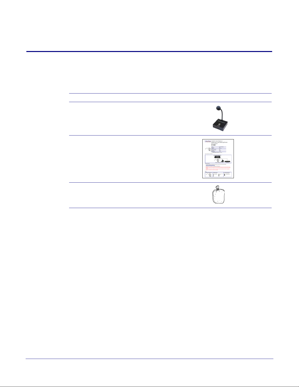
2.1 Parts List
Ta bl e 2-1 illustrates the Multicast VoIP Microphone parts.
Table 2-1. Parts List
Quantity Part Name Picture
1 Multicast VoIP Microphone
Assembly
1 Installation Quick Reference Guide
5
1 Multicast VoIP Microphone
Mounting Accessory Kit
Operations Guide 931431A CyberData Corporation

2.1.1 Multicast VoIP Microphone Connectors
See the following figures and tables to identify the connectors and functions of the Multicast VoIP
Microphone.
Figure 2-1. Connector Locations
Installing the Multicast VoIP Microphone
Parts List
6
Table 2-2. Connector Functions
Connector Function
J2 Push Button
J6 Microphone Interface
Operations Guide 931431A CyberData Corporation
Installing the Multicast VoIP Microphone
Figure 2-2. Connector Locations
Parts List
7
Table 2-3. Connector Functions
Connector Function
J1 PoE Network Connection (RJ-45 ethernet)
Operations Guide 931431A CyberData Corporation
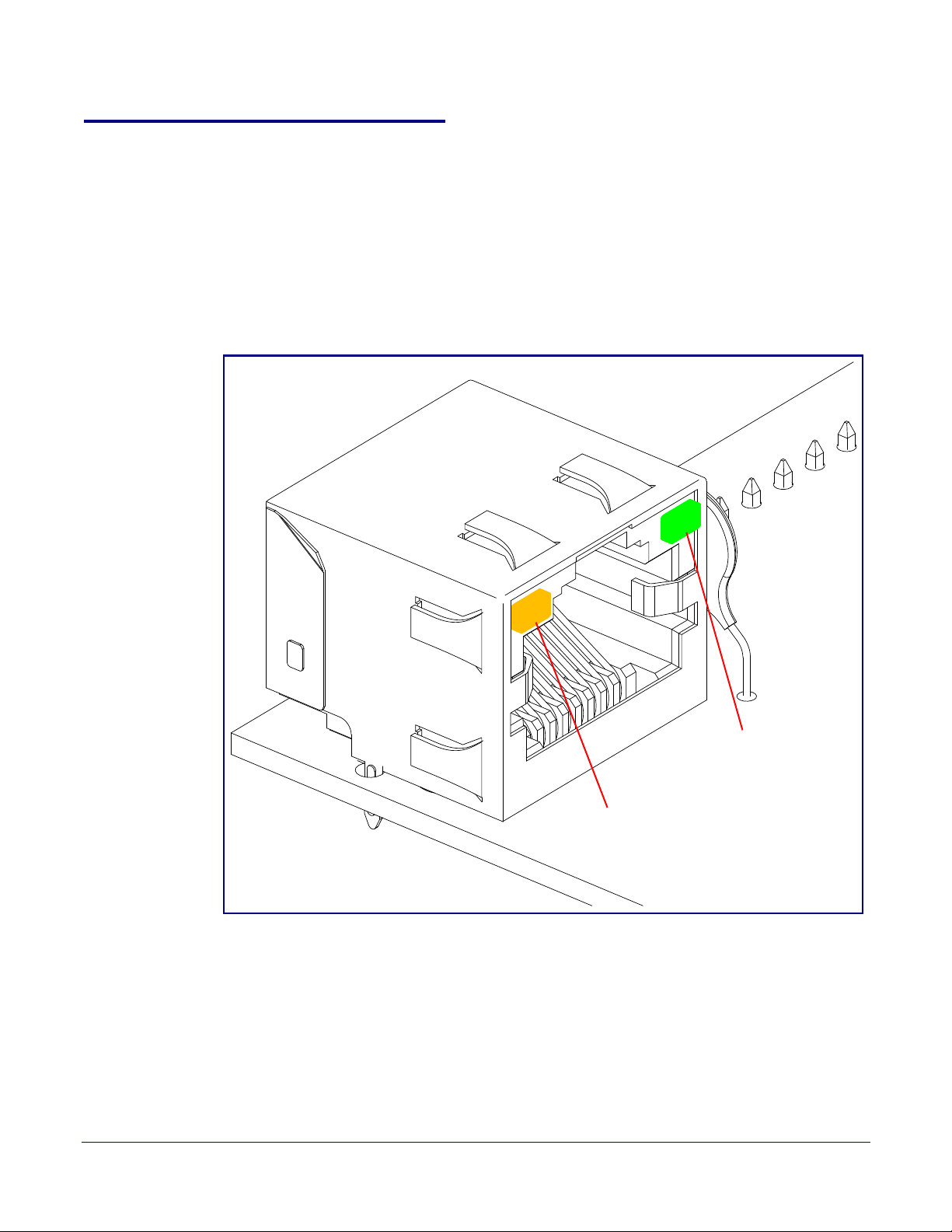
2.1.2 Activity and Link LEDs
Link
Activity
2.1.2.1 Verifying the Network Connectivity and Data Rate
When you plug in the Ethernet cable or power supply to the device, the following occurs:
• The square, AMBER Link/Activity LED blinks when there is network activity (see Figure 2-3).
• The square, GREEN 100Mb Link LED above the Ethernet port indicates that the network
connection has been established (see
Figure 2-3. Activity and Link LED
Figure 2-3).
Installing the Multicast VoIP Microphone
Parts List
8
Operations Guide 931431A CyberData Corporation

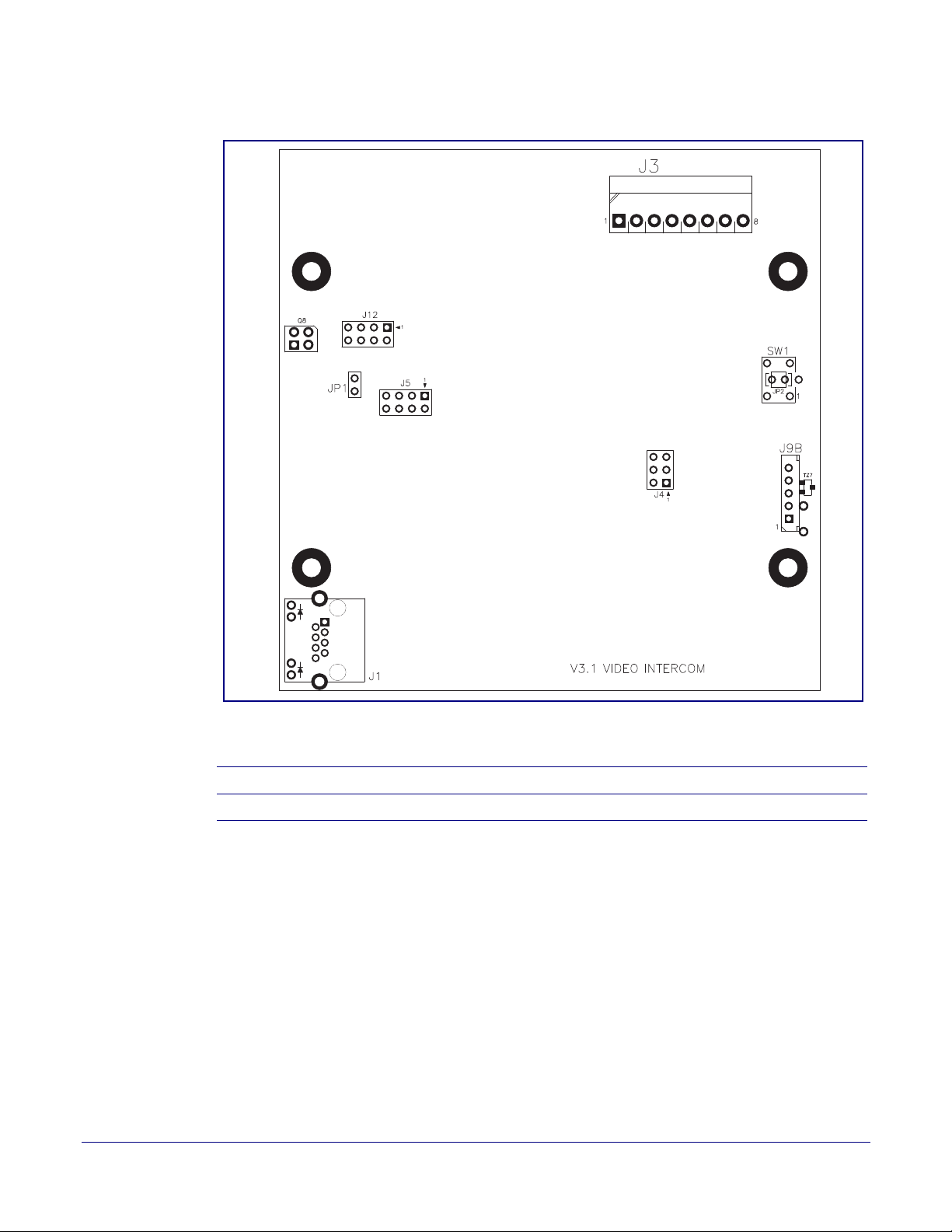
2.1.3 Restoring the Factory Default Settings
Paperclip to
Access RTFM Button
Use a
When troubleshooting configuration problems, it is sometimes convenient to restore the device to the
factory default settings.
Note Each Multicast VoIP Microphone is delivered with factory set default values.
To restore the factory default settings:
1. Press and hold the RTFM button (see SW1 in Figure 2-4) for more than five seconds.
Note The device will use DHCP to obtain the new IP address (DHCP-assigned address or default
to 10.10.10.10 if a DHCP server is not present).
Figure 2-4. RTFM Button
Installing the Multicast VoIP Microphone
Parts List
9
Operations Guide 931431A CyberData Corporation
2.1.4 Call Button and the Call Button LED
Call Button and Call Button LED
2.1.4.1 Call Button LED Function
• Upon initial power or reset, the Call Button LED will illuminate.
• On boot, the Call Button LED will flash ten times a second while setting up the network and
downloading autoprovisioning files.
• The device “autoprovisions” by default, and the initial process may take several minutes as the
device searches for and downloads updates. The Call Button LED will blink during this process.
During the initial provisioning, or after the factory defaults have been reset, the device may
download firmware twice. The device will blink, remain solid for 10 to 20 seconds, and then
resume blinking.
• When the software has finished initialization, the Call Button LED will blink twice.
• On the Device Configuration Page (see Section 2.2.5, "Configure the Device"), there is an
option called Button Lit When Idle. This option sets the normal state for the indicator LED. The
Call Button LED will still blink during initialization.
• After the RTFM button is pressed, the call button LED will turn off for several seconds. It lights
for approximately 25 seconds, fast blinks for 10 seconds, and then stays on while the device is in
operation.
Installing the Multicast VoIP Microphone
Parts List
10
Figure 2-5. Call Button and Call Button LED
Operations Guide 931431A CyberData Corporation

Installing the Multicast VoIP Microphone
Parts List
2.2 Configure the Multicast VoIP Microphone Parameters
To configure the Multicast VoIP Microphone online, use a standard web browser.
11
Configure each Multicast VoIP Microphone and verify its operation bef
are ready to mount an Multicast VoIP Microphone, refer to
Microphone" for instructions.
2.2.1 Factory Default Settings
All Multicast VoIP Microphones are initially configured with the following default IP settings:
When configuring more than one Multicast VoIP Microphone, atta
to the network and configure one at a time to avoid IP address conflicts.
Parameter Factory Default Setting
IP Addressing DHCP
IP Address
Web Access Username admin
Web Access Password admin
Subnet Mask
Default Gateway
a
a
a
ore you mount it. When you
Appendix A, "Mounting the Multicast VoIP
ch the Multicast VoIP Microphones
Table 2-4. Factory Default Settings
10.10.10.10
255.0.0.0
10.0.0.1
a. Default if there is not a DHCP server present.
Operations Guide 931431A CyberData Corporation
Installing the Multicast VoIP Microphone
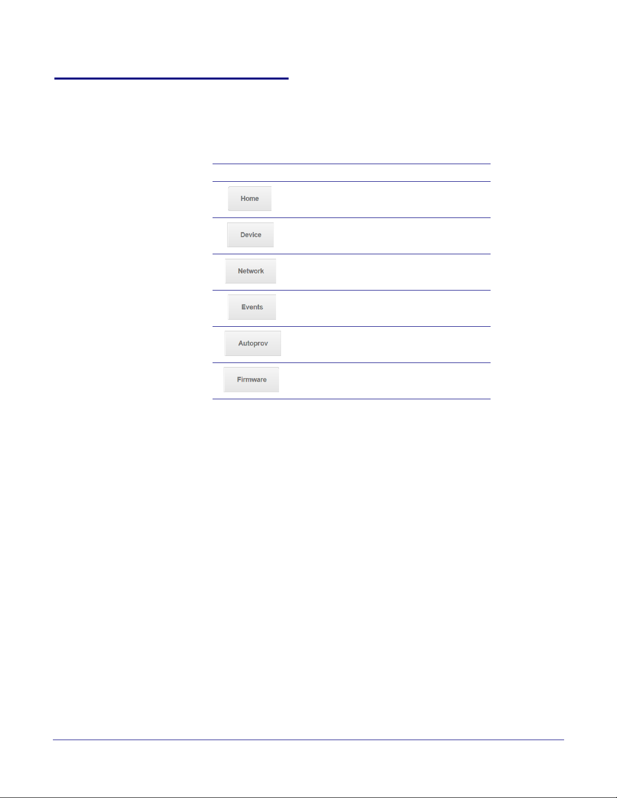
2.2.2 Multicast VoIP Microphone Web Page Navigation
Ta bl e 2-5 shows the navigation buttons that you will see on every Multicast VoIP Microphone web
page.
Table 2-5. Web Page Navigation
Web Page Item Description
Link to the Home page.
Link to the Device page.
Link to the Network page.
Link to the Events page.
Parts List
12
Link to the Autoprovisioning page.
Link to the Firmware page.
Operations Guide 931431A CyberData Corporation
 Loading...