

CyberData 011397, 011398, 011395, 011396 Operation Manual
SIP Talk-Back Speaker
The IP Endpoint Company
Operations Guide
Part #011397*, RAL 9002, Gray White, Standard
Part #011398*, RAL 9003, Signal White, Optional
*Replaces #011180 and 011181
Document Part #931191I
for Firmware Version 11.6.9
CyberData Corporation
3 Justin Court
Monterey, CA 93940
(831) 373-2601
SIP Talk-Back Speaker Operations Guide 931191I
Technical Support
The fastest way to get technical support for your VoIP product is to
submit a VoIP Technical Support form at the following website:
http://support.cyberdata.net/
Phone: (831) 373-2601, Ext. 333
Email: support@cyberdata.net
Fax: (831) 373-4193
Company and product information is at www.cyberdata.net.
Part # 011397
Part # 011398
COPYRIGHT NOTICE:
© 2017, CyberData Corporation, ALL RIGHTS RESERVED.
This manual and related materials are the copyrighted property of CyberData Corporation. No part of
this manual or related materials may be reproduced or transmitted, in any form or by any means
(except for internal use by licensed customers), without prior express written permission of
CyberData Corporation. This manual, and the products, software, firmware, and/or hardware
described in this manual are the property of CyberData Corporation, provided under the terms of an
agreement between CyberData Corporation and recipient of this manual, and their use is subject to
that agreement and its terms.
DISCLAIMER: Except as expressly and specifically stated in a written agreement executed by
CyberData Corporation, CyberData Corporation makes no representation or warranty, express or
implied, including any warranty or merchantability or fitness for any purpose, with respect to this
manual or the products, software, firmware, and/or hardware described herein, and CyberData
Corporation assumes no liability for damages or claims resulting from any use of this manual or such
products, software, firmware, and/or hardware. CyberData Corporation reserves the right to make
changes, without notice, to this manual and to any such product, software, firmware, and/or
hardware.
OPEN SOURCE STATEMENT: Certain software components included in CyberData products are
subject to the GNU General Public License (GPL) and Lesser GNU General Public License (LGPL)
“open source” or “free software” licenses. Some of this Open Source Software may be owned by third
parties. Open Source Software is not subject to the terms and conditions of the CyberData
COPYRIGHT NOTICE or software licenses. Your right to copy, modify, and distribute any Open
Source Software is determined by the terms of the GPL, LGPL, or third party, according to who
licenses that software.
Software or firmware developed by CyberData that is unrelated to Open Source Software is
copyrighted by CyberData, subject to the terms of CyberData licenses, and may not be copied,
modified, reverse-engineered, or otherwise altered without explicit written permission from
CyberData Corporation.
TRADEMARK NOTICE: CyberData Corporation and the CyberData Corporation logos are
trademarks of CyberData Corporation. Other product names, trademarks, and service marks may be
the trademarks or registered trademarks of their respective owners.
The IP Endpoint Company
CyberData Corporation 931191I Operations Guide

Revision Information
Revision 931191I, which corresponds to firmware version 11.6.9, was released on September 22,
2017, and has the following changes:
• Updates Section 1.3, "Product Features"
• Updates Ta bl e 1-1, "Product Specifications"
Browsers Supported
The following browsers have been tested against firmware version 11.6.9:
• Internet Explorer (version: 10)
• Firefox (also called Mozilla Firefox) (version: 23.0.1)
• Chrome (version: 29.0.154.66 m)
• Safari (version: 5.1.7)
Operations Guide 931191I CyberData Corporation
Pictorial Alert Icons
GENERAL ALERT
Hazard Levels
Danger: Indicates an imminently hazardous situation which, if not avoided, will result in death or
serious injury. This is limited to the most extreme situations.
Warning: Indicates a potentially hazardous situation which, if not avoided, could result in death or
serious injury.
General Alert
This pictoral alert indicates a potentially hazardous situation. This alert will be
followed by a hazard level heading and more specific information about the
hazard.
Ground
This pictoral alert indicates the Earth grounding connection point.
Caution: Indicates a potentially hazardous situation which, if not avoided, could result in minor or
moderate injury. It may also alert users against unsafe practices.
Notice: Indicates a statement of company policy (that is, a safety policy or protection of property).
The safety guidelines for the equipment in this manual do not purport to address all the safety issues
of the equipment. It is the responsibility of the user to establish appropriate safety, ergonomic, and
health practices and determine the applicability of regulatory limitations prior to use. Potential safety
hazards are identified in this manual through the use of words Danger, Warning, and Caution, the
specific hazard type, and pictorial alert icons.
CyberData Corporation 931191I Operations Guide
Important Safety Instructions
GENERAL ALERT
GENERAL ALERT
GENERAL ALERT
1. Read these instructions.
2. Keep these instructions.
3. Heed all warnings.
4. Follow all instructions.
5. Do not use this apparatus near water.
6. Clean only with dry cloth.
7. Do not block any ventilation openings. Install in accordance with the manufacturer’s instructions.
8. Do not install near any heat sources such as radiators, heat registers, stoves, or other apparatus
(including amplifiers) that produce heat.
9. Do not defeat the safety purpose of the polarized or grounding-type plug. A polarized plug has
two blades with one wider than the other. A grounding type plug has two blades and a third
grounding prong. The wide blade or the third prong are provided for your safety. If the provided
plug does not fit into your outlet, consult an electrician for replacement of the obsolete outlet.
10. Protect the power cord from being walked on or pinched particularly at plugs, convenience
receptacles, and the point where they exit from the apparatus.
11. Only use attachments/accessories specified by the manufacturer.
12. Refer all servicing to qualified service personnel. Servicing is required when the apparatus has
been damaged in any way, such as power-supply cord or plug is damaged, liquid has been
spilled or objects have fallen into the apparatus, the apparatus has been exposed to rain or
moisture, does not operate normally, or has been dropped.
13. Prior to installation, consult local building and electrical code requirements.
Warn in g
Electrical Hazard: This product should be installed by a licensed electrician
according to all local electrical and building codes.
Warn in g
Electrical Hazard: To prevent injury, this apparatus must be securely attached to
the floor/wall in accordance with the installation instructions.
Warn in g
The PoE connector is intended for intra-building connections only and does not
route to the outside plant.
CyberData Corporation 931191I Operations Guide

Abbreviations and Terms
Abbreviation or Term Definition
A-law A standard companding algorithm, used in European digital
communications systems to optimize, i.e., modify, the dynamic range of an
analog signal for digitizing.
AVP Audio Video Profile
Cat 5 TIA/EIA-568-B Category 5
DHCP Dynamic Host Configuration Protocol
LAN Local Area Network
LED Light Emitting Diode
Mbps Megabits per Second.
NTP Network Time Protocol
PBX Private Branch Exchange
PoE Power over Ethernet (as per IEEE 802.3af standard)
RTFM Reset Test Function Management
SIP Session Initiated Protocol
u-law A companding algorithm, primarily used in the digital telecommunication
UC Unified Communications
VoIP Voice over Internet Protocol
CyberData Corporation 931191I Operations Guide

Contents
Chapter 1 Product Overview 1
1.1 How to Identify This Product .....................................................................................................1
1.2 Installation ................................................................................................................................2
1.3 Product Features ......................................................................................................................3
1.4 Supported Protocols .................................................................................................................4
1.5 Supported SIP Servers .............................................................................................................4
1.6 Product Specifications ..............................................................................................................5
1.7 Optional Connections (J9 and J10) ..........................................................................................6
1.8 Compliance ..............................................................................................................................6
1.8.1 CE Testing ......................................................................................................................6
1.8.2 FCC Statement ..............................................................................................................6
1.9 SIP Talk-Back Speaker Modes .................................................................................................7
1.9.1 Optional 011185 Remote Call Button (sold separately) .................................................7
1.9.2 Normal Mode ..................................................................................................................7
1.9.3 Monitor Mode ...............................................................................................................10
Chapter 2 Installing the SIP Talk-Back Speaker 12
2.1 Parts List ................................................................................................................................12
2.2 Device Configuration ..............................................................................................................13
2.2.1 Connect Power to the Speaker ....................................................................................14
2.2.2 Installation Options .......................................................................................................17
2.2.3 Confirm that the Speaker is Operational and Linked to the Network ..........................23
2.2.4 Confirm the IP Address and Test the Audio .................................................................24
2.2.5 Adjust the Volume ........................................................................................................25
2.2.6 How to Set the Factory Default Settings .......................................................................26
2.3.1 Factory Default Settings ...............................................................................................27
2.3.2 SIP Talk-Back Speaker Web Page Navigation .............................................................28
2.3.3 Using the Toggle Help Button .......................................................................................29
2.3.4 Log in to the Configuration Home Page .......................................................................31
2.3.5 Configure the Device ....................................................................................................35
2.3.6 Configure the Network Parameters .............................................................................45
2.3.7 Configure the SIP (Session Initiation Protocol) Parameters .........................................48
2.3.8 Configure the Multicast Parameters .............................................................................58
2.3.9 Configure the Sensor Configuration Parameters ..........................................................61
2.3.10 Configure the Audio Configuration Parameters ..........................................................65
2.3.11 Configure the Events Parameters ..............................................................................72
2.3.12 Configure the Autoprovisioning Parameters ...............................................................78
2.4.1 Downloading the Firmware ...........................................................................................90
2.4.2 Reboot the Device ........................................................................................................92
2.5.1 Command Interface Post Commands ..........................................................................93
i
Appendix A Mounting the Speaker 97
A.1 Mount the Speaker ................................................................................................................97
A.2 Dimensions ............................................................................................................................99
Appendix B Setting up a TFTP Server 100
B.1 Set up a TFTP Server ..........................................................................................................100
B.1.1 In a LINUX Environment ............................................................................................100
B.1.2 In a Windows Environment .......................................................................................100
Appendix C Troubleshooting/Technical Support 101
C.1 Frequently Asked Questions (FAQ) ......................................................................................101
C.2 Documentation .....................................................................................................................101
C.3 Contact Information ..............................................................................................................102
Operations Guide 931191I CyberData Corporation

C.4 Warranty and RMA Information ............................................................................................102
Index 103
Operations Guide 931191I CyberData Corporation
1 Product Overview
SIP Talk Back Speaker
011397A / 021515FI2
www.cyberdata.net
This device complies with part 15 of the FCC Rules. Operation is subject to the following two conditions:
(1) this device may not cause harmful interference, and (2) this device must accept any interference received,
including interference that may cause undesired operation.
CAN ICES-3 (A)/NMB-3(A)
V
00:20:F7:03:83:CA
397000001
Serial number begins with 393
11.6.9
Model number
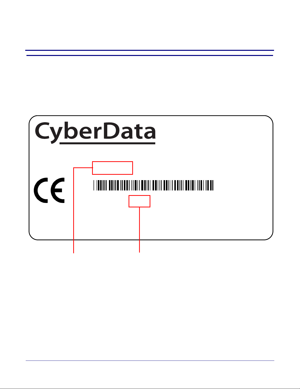
1.1 How to Identify This Product
To identify the SIP Talk-Back Speaker, look for a model number label similar to the one shown
in Figure 1-1. The model number on the label should be one of the following:
• 011397, RAL 9002, Gray White, Standard Color
• 011398, RAL 9003, Signal White, Optional Color
Figure 1-1. Model Number Label
1
Operations Guide 931191I CyberData Corporation
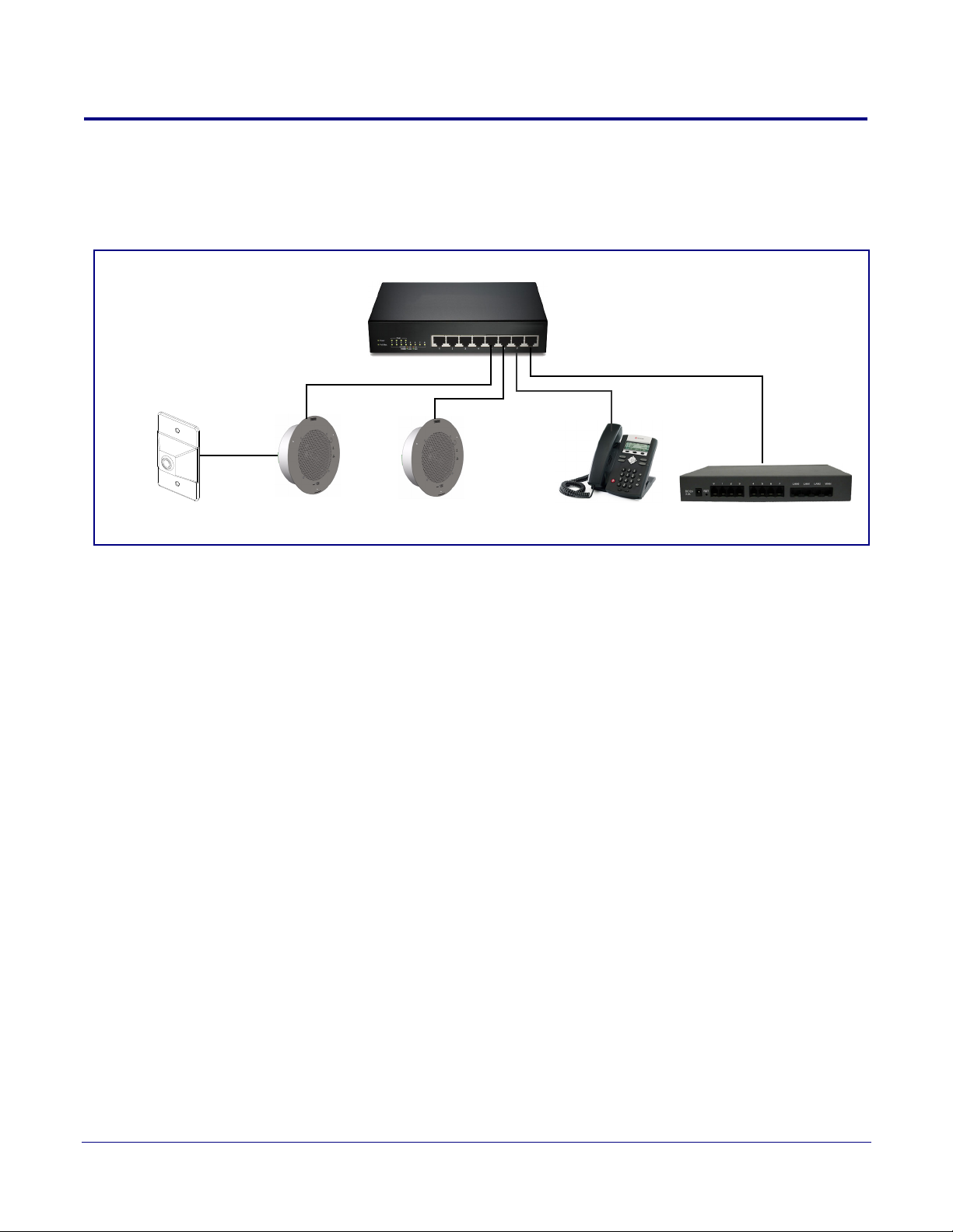
1.2 Installation
Remote Call Button
802.3af/at Compliant Ethernet Switch
IP Phone IP PBX Server
SIP Talk-Back Speakers
(sold separately)
Figure 1-2 illustrates a typical configurations for the SIP Talk-Back Speaker.
Figure 1-2. Typical Installation
Product Overview
Installation
2
See the following sections for other installation options:
• Section 2.2.1.3, "Running the SIP Talk-Back Speaker with Auxiliary Power"
• Section 2.2.2.4, "SIP Talk-Back Speaker with an External Device"
• Section 2.2.2.5, "SIP Talk-Back Speaker with Auxiliary Speaker Connection"
• Section 2.2.2.6, "SIP Talk-Back Speaker with Line Out"
Operations Guide 931191I CyberData Corporation

1.3 Product Features
• Full-duplex (SIP) or half-duplex (push to talk)
• Page to Polycom phones
• Added stored messages with option to enable or disable playback
• Support for security code to prevent unwanted SIP calls
• Optional red/green/blue/white strobe kit connection available
• Autoprovisioning via HTTP, HTTPS, or TFTP
• HTTPS or HTTP web based configuration. HTTPS is enabled by default.
• 802.11q VLAN tagging
• Configurable sense input for use with fault detection or with optional lighted button kit
• Configurable event generation for device health and status monitoring
• Support for G.711 u-law, G.711 a-law, and G.722 codecs.
• Powered via PoE (802.3AF or 802.3AT) or 24V auxiliary power supply (not included)
• Enhanced interoperability for hosted environments
• IP (RFC 3261) compatible
• Night Ringer function
• Plays audio from Multicast
• Web-based configuration
• Paging prioritization and background music
• User upgradeable firmware via web interface or autoprovisioning
• External volume control
• Small footprint
• High efficiency speaker driver
• IGMP l SIP endpoint or Multicast group member
• Network-adjustable speaker volume
• Optional auxiliary speaker available to increase audio coverage - Part #011120/011121
• Optional clock kit available - Part #011153/011154
• Support for 10 multicast paging groups
• Support for multiple SIP servers for redundancy
• Support for Cisco SRST resiliency
• Relay for activating door locks, external amplifiers, etc.
• Line-level audio output for connecting to an external amplifier
Product Overview
Product Features
3
Operations Guide 931191I CyberData Corporation

1.4 Supported Protocols
The SIP Talk-Back Speaker supports:
•SIP
• Multicast
• HTTP Web-based configuration
Provides an intuitive user interface for easy system configuration and verification of speaker
operations.
• DHCP Client
Dynamically assigns IP addresses in addition to the option to use static addressing.
• HTTP TCP Post auto-updating event notification in XML format
• TFTP Client
Facilitates hosting for the configuration file for Autoprovisioning.
• Audio Encodings
PCMU (G.711 mu-law)
PCMA (G.711 A-law)
Packet Time 20 ms
Product Overview
Supported Protocols
4
1.5 Supported SIP Servers
The following link contains information on how to configure the speaker for the supported SIP
servers:
http://www.cyberdata.net/connecting-to-ip-pbx-servers/
Operations Guide 931191I CyberData Corporation

Product Overview
Product Specifications
1.6 Product Specifications
Table 1-1. Product Specifications
Category Specification
Audio output 802.3af - SPL 109.2 dB @ 1 meter
802.3at - SPL 111.9 dB @ 1 meter
o
Operating Range Temperature: -40
Humidity: 5-95%, non-condensing
o
Storage Temperature
Storage Altitude
Ethernet port baud rate 10/100 Mbps
Protocol SIP RFC 3261 Compatible
Power Input (J1) PoE 802.3af (as per IEEE 802.3af standard from a UL-listed, LPS-rated limited power source)
or Auxiliary Power Inputa
(Terminal Block J10)
Total Power ~ 15W
Network Line loss ~ 2W
C to 70o C (-40o F to 158o F)
-40
Up to 15,000 ft. (4573 m)
802.3at
44-57 VDC (48 VDC nominal) at 350mA
24 VDC at 1A (from a UL-listed, LPS-rated power supply)
C to 55o C (-40o F to 131o F)
5
Total Pwr @ VoIP
Speaker
Total available audio
power
Idle PWR (losses/CPU) ~ 3W
Payload types G.711 µ-law, G.711 a-law, and G.722
Warranty 2 years limited
Dimensions 9 in. [228.6 mm] x 2.4 in. [60.96 mm]
Weight 2.8 lbs./shipping weight of 3.8 lbs.
Compliance CE; EMC Directive – Class A EN 55032 & EN 55024, LV Safety Directive – EN 60950-1, RoHS
Part number 011397*, RAL 9002, Gray White, Standard Color
~ 13W
~ 10W
(1.3 kg/shipping weight of 1.7 kg)
Compliant, FCC; Part 15 Class A, Industry Canada; ICES-3 Class A, IEEE 802.3 Compliant
011398*, RAL 9003, Signal White, Optional Color
*Replaces 011180 and 011181.
a.Auxiliary power input for use when PoE power is not available. 24 VDC @ 1A. Do not use auxiliary power input
when speaker J1 is connected to a PoE power source.
Operations Guide 931191I CyberData Corporation
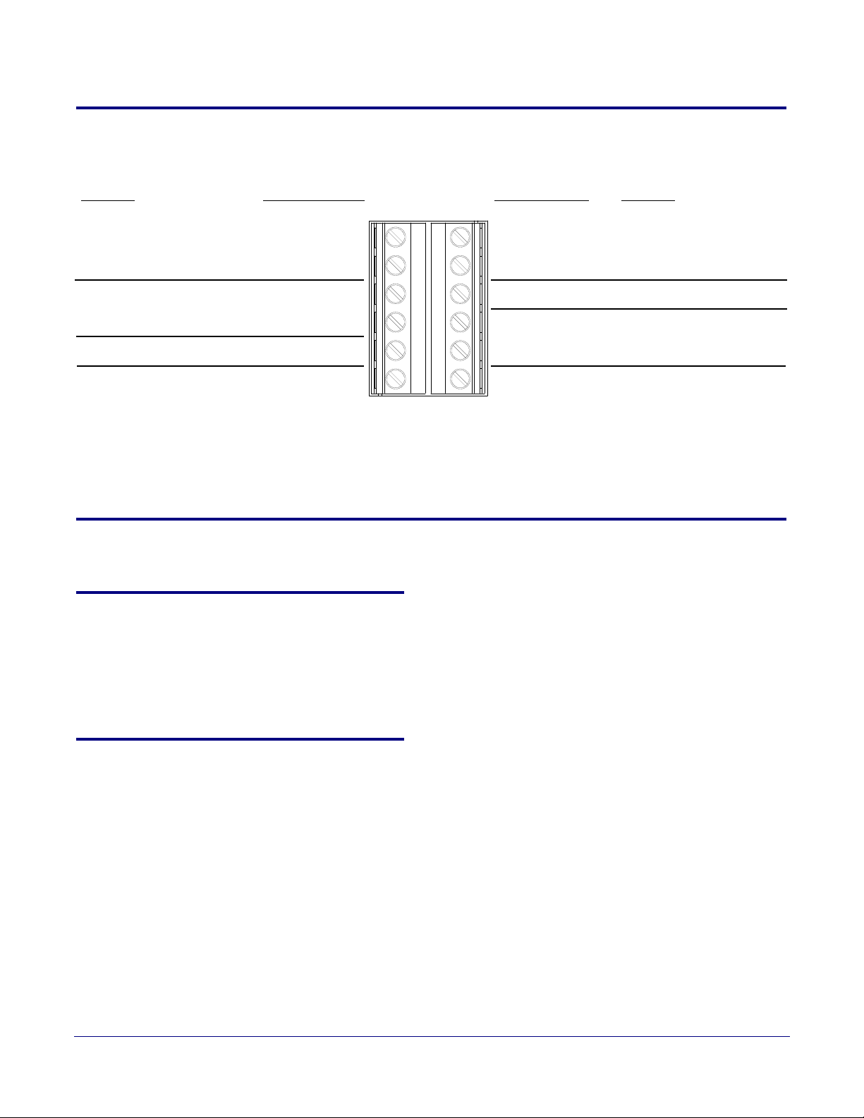
1.7 Optional Connections (J9 and J10)
AUX SPEAKER (-)
AUX SPEAKER (+)
GND
LINE OUT (-)
LINE OUT (+)
BUTTON LED (+)
RELAY NO
RELAY COM
AUX POWER (-)
AUX POWER (+)
(+24VDC @ 1A)
J10
J9
*Auxiliary power input for
use when PoE power is not
available. +24 VDC @ 1A.
Relay contacts rated at
30 VDC @ 1A.
Auxiliary 8-Ohm speaker
connection (not to be used
when the Clock is connected.
Audio line - level output to
external audio amplifier.
2v P-P into 10k Ohms.
*Do not use auxiliary power input when speaker J1 is connected to a PoE power source.
Function
FunctionJ10 Connections J9 Connections
BTN SENSE
BUTTON LED (-)
CLASS II WIRING
Figure 1-3. Optional Connections (J9 and J10)
Product Overview
Optional Connections (J9 and J10)
6
1.8 Compliance
1.8.1 CE Testing
1.8.2 FCC Statement
CE testing has been performed according to EN ISO/IEC 17050 for Emissions, Immunity, and Safety.
Note You can download the Declaration of Conformity document from the Downloads tab of the
product’s webpage.
This equipment has been tested and found to comply with the limits for a Class B digital device,
pursuant to part 15 of the FCC Rules. These limits are designed to provide reasonable protection
against harmful interference when the equipment is operated in a commercial environment. This
equipment generates, uses, and can radiate radio frequency energy and, if not installed and used in
accordance with the instruction manual, may cause harmful interference to radio communications.
Operation of this equipment in a residential area is likely to cause harmful interference in which case
the user will be required to correct the interference at his own expense.
Operations Guide 931191I CyberData Corporation
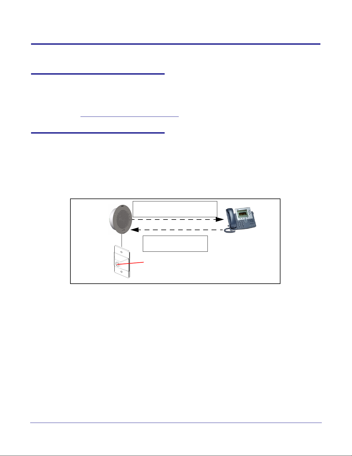
1.9 SIP Talk-Back Speaker Modes
IP Phone
SIP Talk-Back
Speaker
SIP Talk-Back Speaker makes a
call or dials a SIP extension.
Phone user dials the SIP
Talk-Back Speaker.
OR
Push the Call Button
Note: See Section 1.9.1, "Optional 011185
Remote Call Button (sold separately)"
1.9.1 Optional 011185 Remote Call Button (sold separately)
Section 1.9, "SIP Talk-Back Speaker Modes" shows the optional 011185 Remote Call Button which
is sold separately. For more information about this product, go to the following webpage:
http://www.cyberdata.net/voip/011185/
1.9.2 Normal Mode
•In Normal Mode, a person can use the Remote Call Button and the SIP Talk-Back Speaker to
call an IP phone or a phone user can call the SIP Talk-Back Speaker. See
Note Normal Mode requires the use of the Button Installed and Enable Push to Talk features
listed on the Device Configuration Page.
Product Overview
SIP Talk-Back Speaker Modes
Figure 1-4.
7
Figure 1-4. Normal Mode
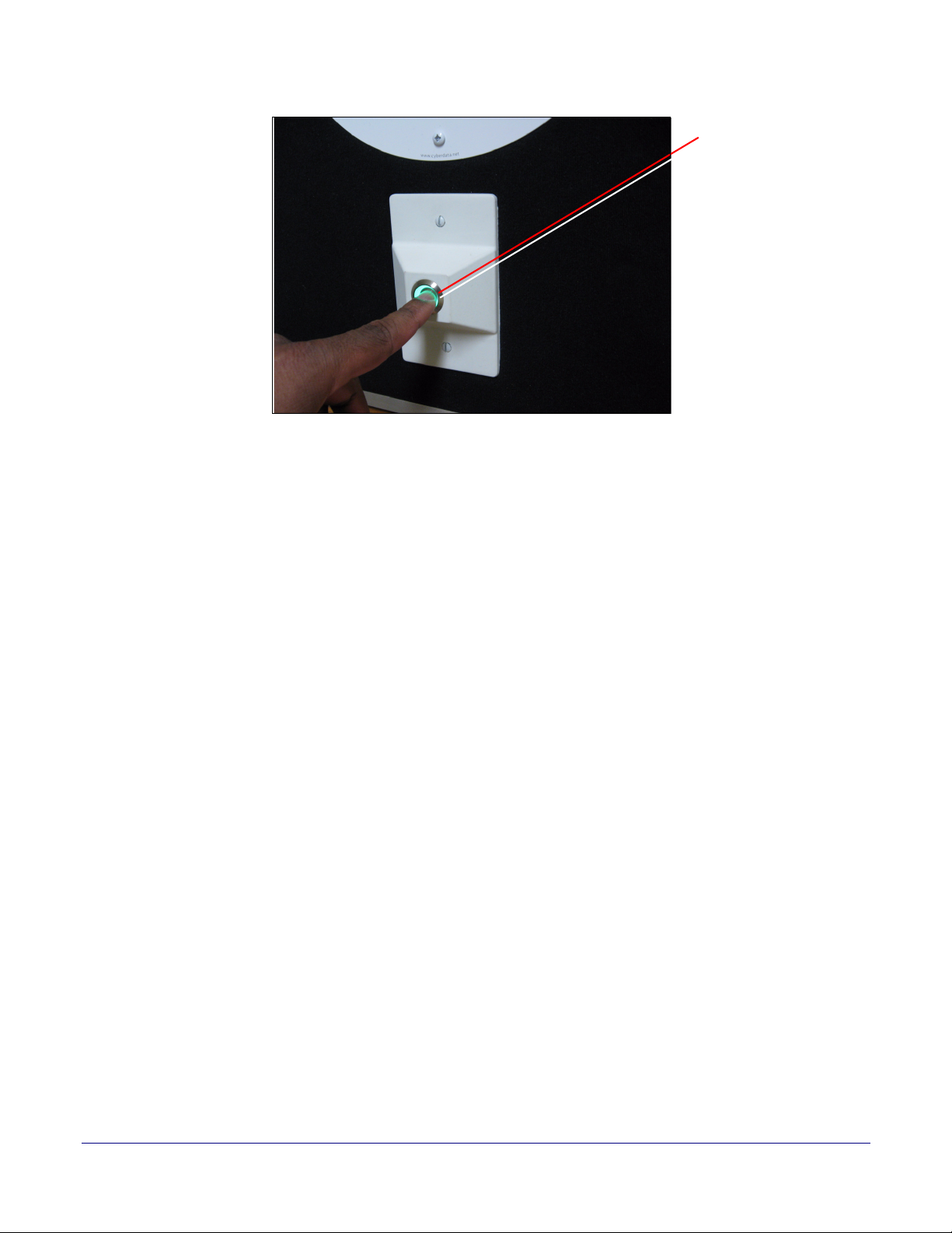
• Push the Call Button to make a call or dial the SIP extension. See Figure 1-5.
Figure 1-5. Push the Call Button to Make a Call
Operations Guide 931191I CyberData Corporation
Product Overview
Push the Call Button
Note: See Section 1.9.1,
"Optional 011185 Remote
Call Button (sold separately)"
SIP Talk-Back Speaker Modes
8
Operations Guide 931191I CyberData Corporation
Product Overview
Hold down the Call Button
while talking
Note: See Section 1.9.1,
"Optional 011185 Remote
Call Button (sold separately)"
Release the Call Button
while listening
Note: See Section 1.9.1,
"Optional 011185 Remote
Call Button (sold sepa-
rately)"
SIP Talk-Back Speaker Modes
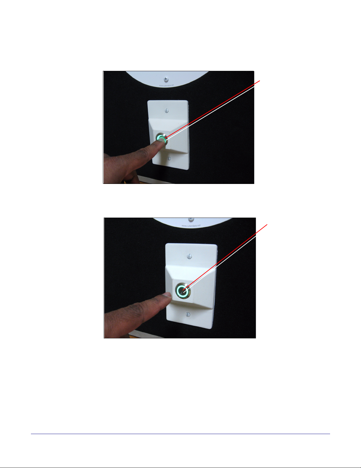
• To talk to someone on the other end, the person at the SIP Talk-Back Speaker, must hold down
the Call Button while they are talking to the person on the other end. See
Figure 1-6.
Figure 1-6. Hold Down the Call Button While Talking
• To listen to someone talking on the other end, the person at the SIP Talk-Back Speaker must
release the Call Button. See
Figure 1-7.
9
Figure 1-7. Release the Call Button While Listening
Operations Guide 931191I CyberData Corporation
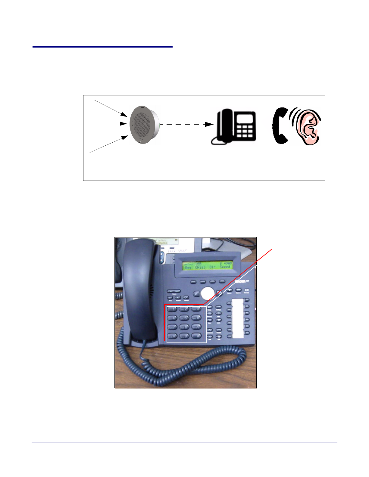
1.9.3 Monitor Mode
IP Phone
Ta lk - B ac k
Speaker
Sound, noise, or
activity near the
SIP Talk-Back
Dial the pre-programmed
Monitor Extension
•In Monitor Mode, the person on the phone can listen to any activity that is occurring near the
Push-to-Talk Speaker. See
• The Call Button is not used during Monitor Mode.
• Monitor Mode is controlled by the phone instead of the Push-to-Talk Speaker.
• To initiate the Monitor Mode, someone on a phone must dial the pre-programmed Monitor
Extension. See
Figure 1-8.
Figure 1-8. Monitor Mode
Figure 1-9.
Product Overview
SIP Talk-Back Speaker Modes
10
Figure 1-9. Dial the Monitor Extension
Operations Guide 931191I CyberData Corporation
Product Overview
Talking and listening
modes are controlled by
the phone keypad
SIP Talk-Back Speaker Modes
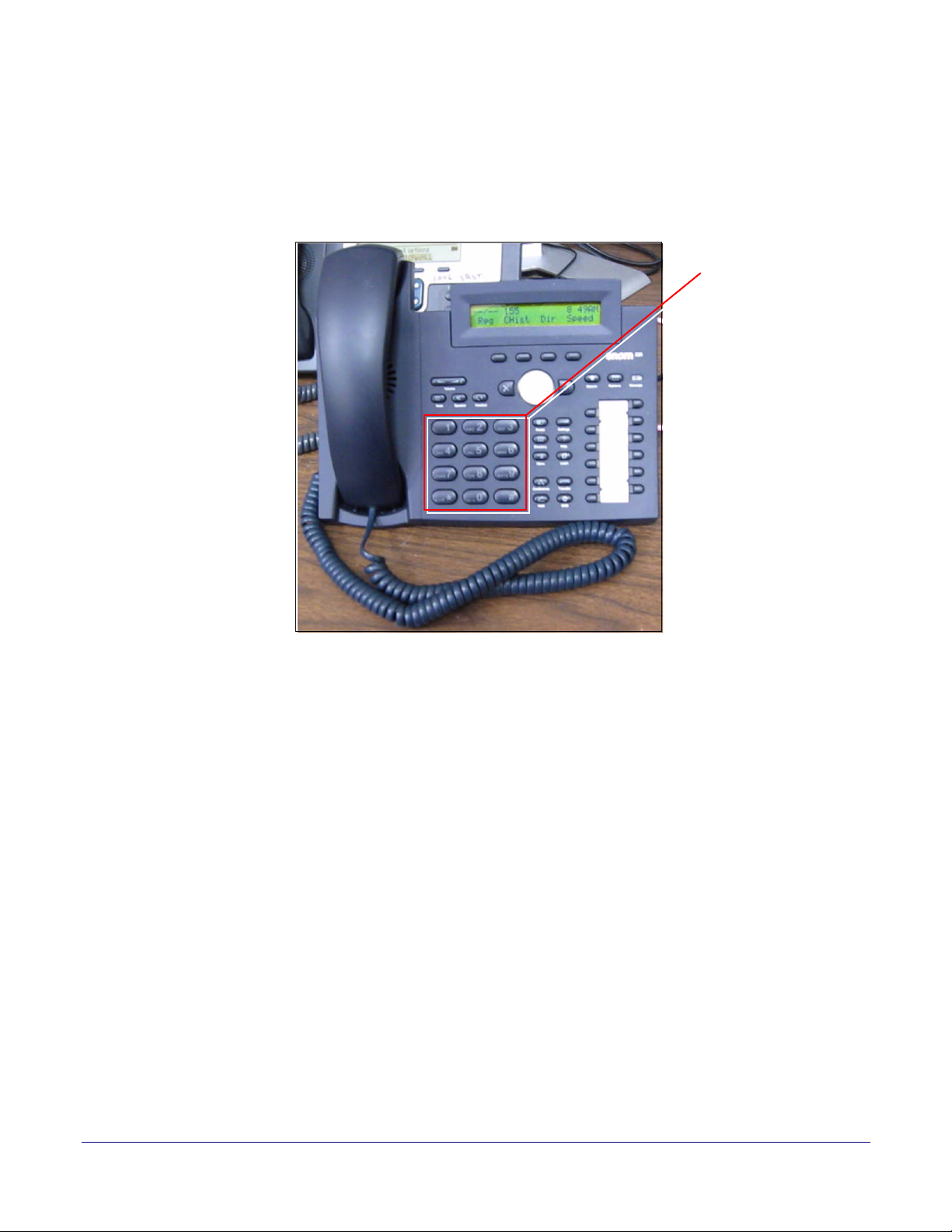
•In Monitor Mode, the "talking mode" and the "listening mode" are controlled by one of the pre-
programmed buttons on the phone keypad. Therefore, if someone is in the "listening mode,"
they must press a pre-programmed keypad button to enter the "talking mode." Conversely, if
someone is in the "talking mode," they must press a pre-programmed keypad button to enter the
"listening mode."
Figure 1-10. Talking and Listening Modes are Controlled by the Phone Keypad
11
Operations Guide 931191I CyberData Corporation
2 Installing the SIP Talk-Back Speaker
2.1 Parts List
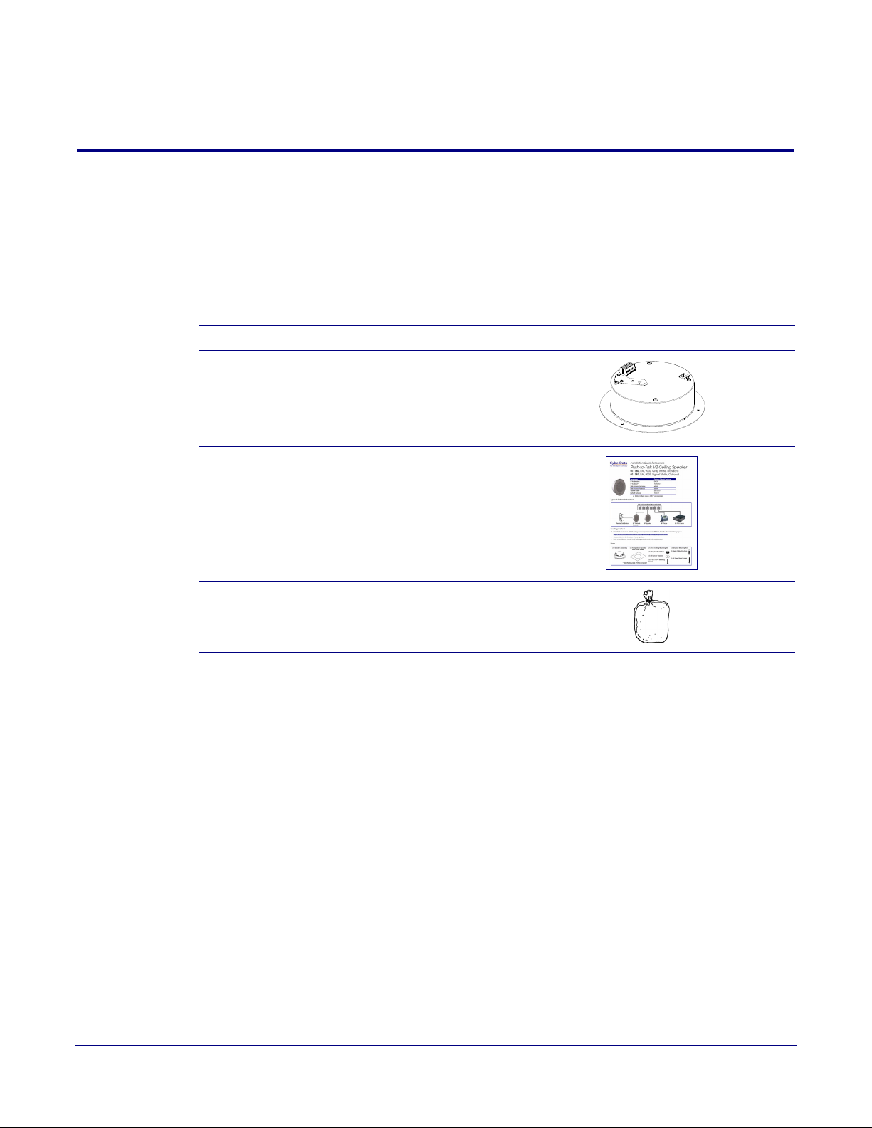
Ta bl e 2-1 illustrates the parts for each speaker and includes kits for the drop ceiling and drywall
mounting.
12
Note The installation template for the SIP Talk-Back Speaker is locate
Reference Guide that is included in the packaging with each speaker.
Table 2-1. Parts
Quantity Part Name Illustration
1 SIP Talk-Back Speaker Assembly
1 Installation Quick Reference Guide
1 Speaker Mounting Accessory Kit
d on the Installation Quick
Operations Guide 931191I CyberData Corporation

2.2 Device Configuration
Set up and configure each speaker before you mount it.
CyberData delivers each speaker with the following factory default values:
Table 2-2. Factory Network Default Settings—Default of Network
Parameter Factory Default Setting
IP Addressing DHCP
IP Address
Web Access Username admin
Web Access Password admin
Subnet Mask
Default Gateway
a
a
a
a. Default if there is not a DHCP server present.
10.10.10.10
255.0.0.0
10.0.0.1
Installing the SIP Talk-Back Speaker
Device Configuration
13
Operations Guide 931191I CyberData Corporation
2.2.1 Connect Power to the Speaker
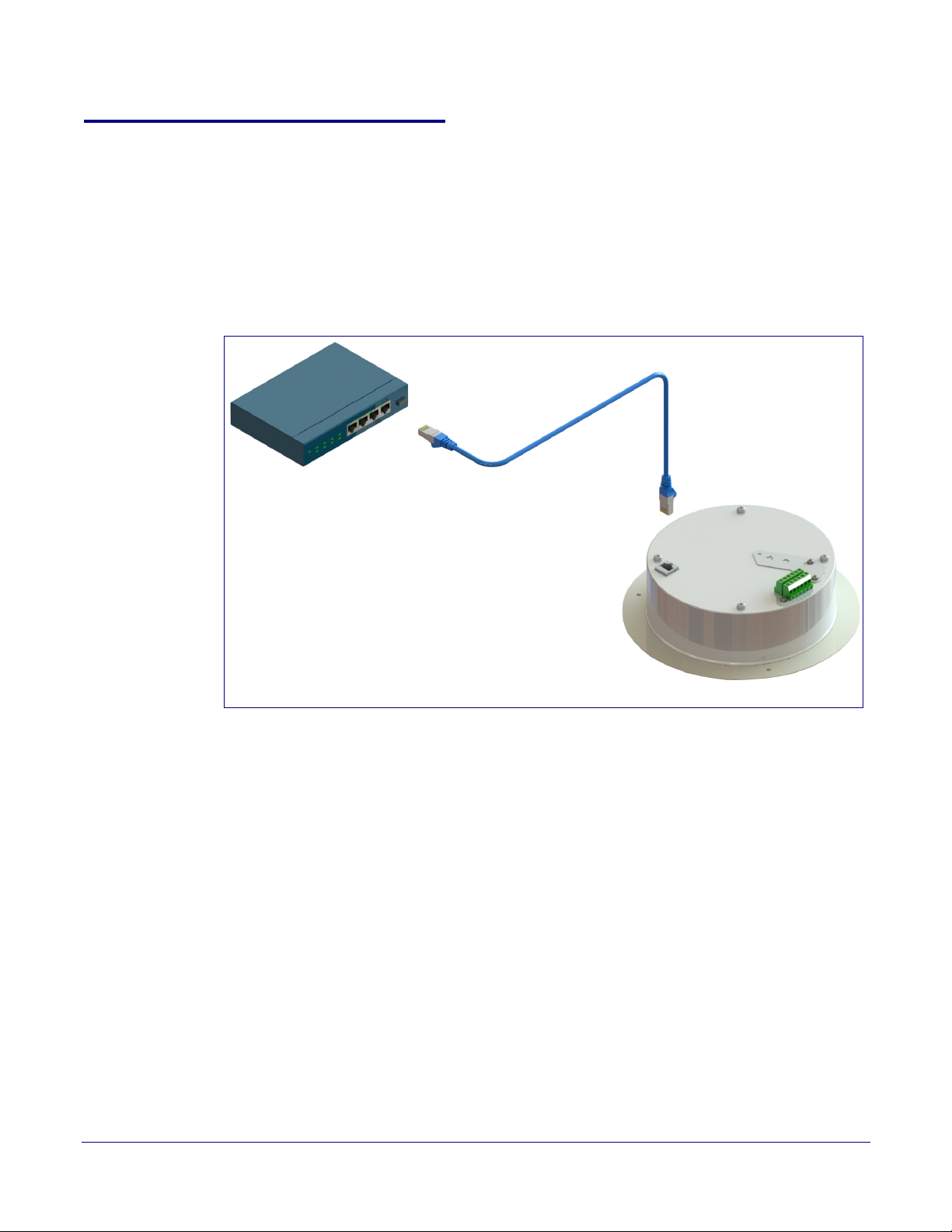
802.3af Compliant PoE Switch
Cat 5 Ethernet cable
SIP Talk-Back Speaker
Figure 2-1 through Figure 2-3 illustrates how to connect power to the SIP Talk-Back Speaker.
2.2.1.1 SIP Talk-Back Speaker to a 802.3af Compliant PoE Switch
Figure 2-1 illustrates how to connect the SIP Talk-Back Speaker to a 802.3af compliant PoE switch
via a Cat 5 Ethernet cable.
Figure 2-1. SIP Talk-Back Speaker to a 802.3af Compliant PoE Switch
Installing the SIP Talk-Back Speaker
Device Configuration
14
Operations Guide 931191I CyberData Corporation
Installing the SIP Talk-Back Speaker
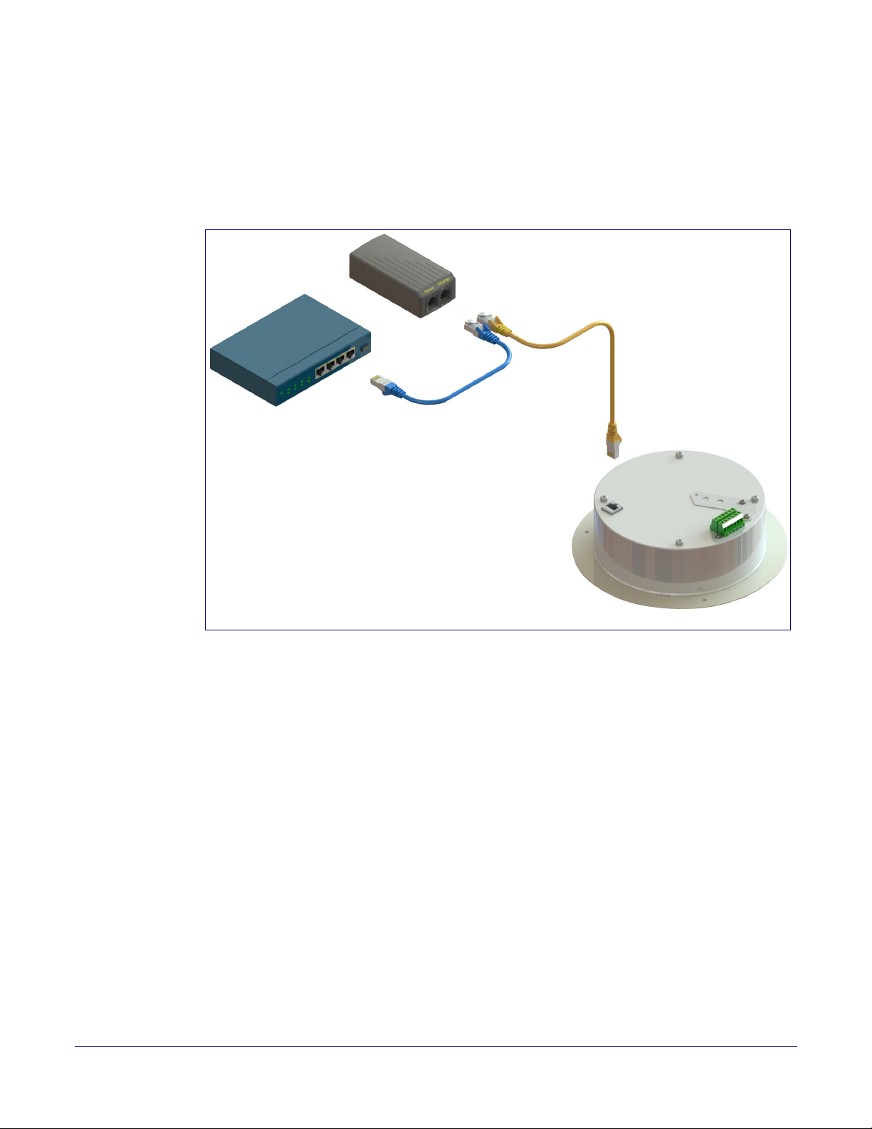
PoE Injector (Part #010867A)
Non PoE Switch
SIP Talk-Back Speaker
Cat 5 Ethernet cable
Device Configuration
2.2.1.2 SIP Talk-Back Speaker (with PoE Injector) to a 802.3af Compliant PoE Switch
In Figure 2-2, if a PoE switch is not available, you will need a PoE Injector, part #010867A (ordered
separately). A PoE Injector is a power supply solution for those who have a standard Non PoE
Switch.
Figure 2-2. SIP Talk-Back Speaker (with PoE Injector) to a Non PoE Switch
15
Operations Guide 931191I CyberData Corporation
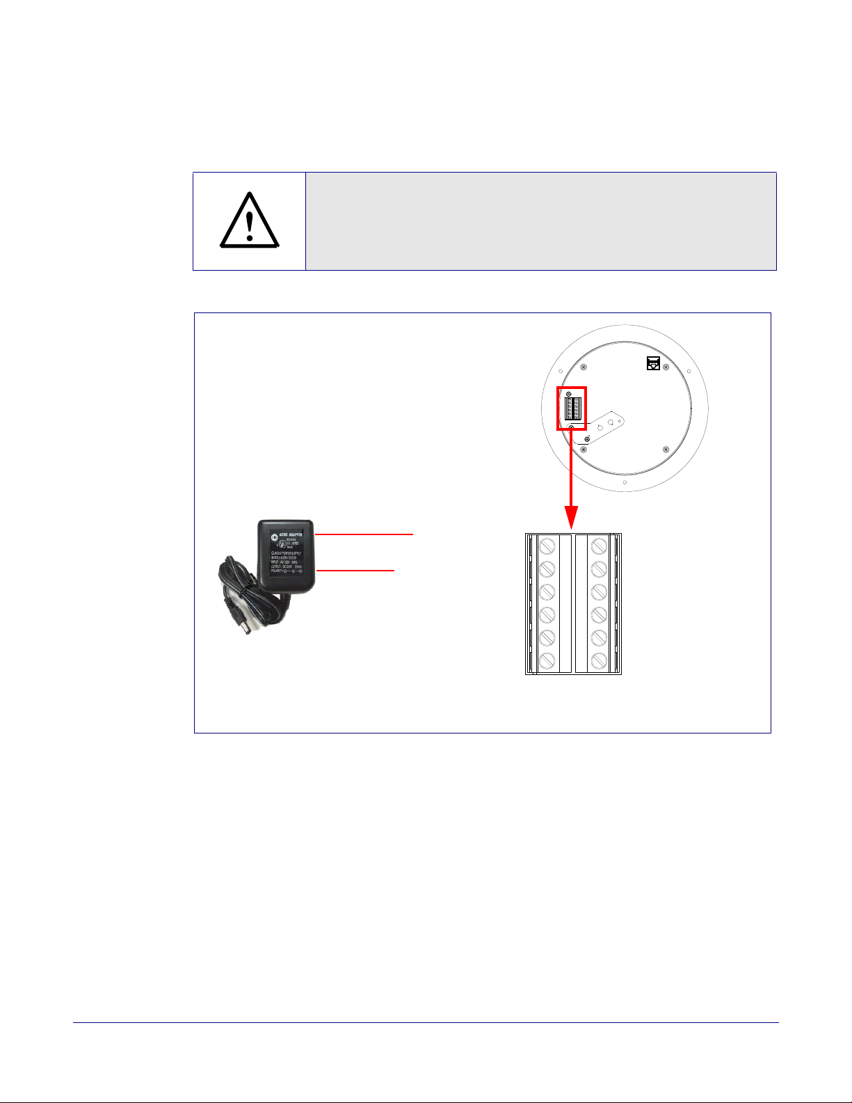
2.2.1.3 Running the SIP Talk-Back Speaker with Auxiliary Power
GENERAL ALERT
GND
AC adaptor
+12-24 VDC @ 1 Amps
(UL-listed, LPS-rated)
+12-24 VDC
Speaker
AUX SPEAKER (-)
AUX SPEAKER (+)
GND
LINE OUT (-)
LINE OUT (+)
+5V OUT
RELAY NO
RELAY COM
AUX POWER (-)
AUX POWER (+)
(+24VDC @ 1A)
J10
J9
N/C
N/C
CLASS II WIRING
In Figure 2-3, the power for the SIP Talk-Back Speaker can either come from an 802.3af Network
connection or from an external source.
Caution
Operational Note: Do not connect an auxiliary power supply when the SIP
Talk-Back Speaker is connected to a PoE power source through J1. Improper
operation or equipment damage may occur.
Installing the SIP Talk-Back Speaker
Device Configuration
16
Figure 2-3. Running the Speaker with Auxiliary Pow
er
Operations Guide 931191I CyberData Corporation
2.2.2 Installation Options
Port C over
Port C over
Flip Over
Ceiling Speaker Assembly
Mounting Screw
Mounting Screw
Strobe Cable
One (1) Meter
Slot
Slot
to
Backplate
RGB Strobe Assembly
Connect Through Backplate / Slot
071069*
Mounting Screw
Cable
Adapter
J1
J1
Key Bump
Key Bump
Slot
Dimple
Dimple
Auxiliary RGB Strobe
This section shows various installation options for the SIP Talk-Back Speaker.
2.2.2.1 Connecting the Auxiliary RGB Strobe to the SIP SPeaker
1. Connect the one meter strobe cable to the adapter cable. See Figure 2-4.
2. Remove the mounting screws and port cover from the SIP Speaker. See Figure 2-4.
3. Align the key bump on the adapter cable to the key bump slot on the SIP Speaker. See Figure 2-
4.
4. Replace the port cover and mounting screw. See Figure 2-4.
Figure 2-4. Connecting the Auxiliary RGB Strobe Kit to the SIP Speaker
Installing the SIP Talk-Back Speaker
Device Configuration
17
Operations Guide 931191I CyberData Corporation
2.2.2.2 Connecting the SIP RGB Strobe to the SIP SPeaker
Port C over
Port C over
Flip Over
Ceiling Speaker Assembly
Mounting Screw
Mounting Screw
Strobe Cable
One (1) Meter
Connect Through Backplate / Slot
071069*
Cable
Adapter
Key Bump
Key Bump
Slot
Dimple
Dimple
JX
SIP RGB Strobe Board
JX
to
1. Connect the one meter strobe cable to the adapter cable. See Figure 2-5.
2. Remove the mounting screws and port cover from the SIP Speaker. See Figure 2-5.
3. Align the key bump on the adapter cable to the key bump slot on the SIP Speaker. See Figure 2-
5.
4. Replace the port cover and mounting screw. See Figure 2-4.
Figure 2-5. Connecting the SIP RGB Strobe to the SIP Speaker
Installing the SIP Talk-Back Speaker
Device Configuration
18
Operations Guide 931191I CyberData Corporation
Installing the SIP Talk-Back Speaker
Speaker
Back View
AUX SPEAKER (-)
AUX SPEAKER (+)
GND
LINE OUT (-)
LINE OUT (+)
BUTTON LED (-)
BTN SENSE
BUTTON LED (+)
RELAY NO
RELAY COM
AUX POWER (-)
AUX POWER (+)
(+24VDC @ 1A)
J10
J9
CLASS II WIRING
High-purity copper
16 AWG wire and a
maximum length of
20 feet
Remote Call Button
Note: See Section 1.9.1, "Optional 011185
Remote Call Button (sold separately)"
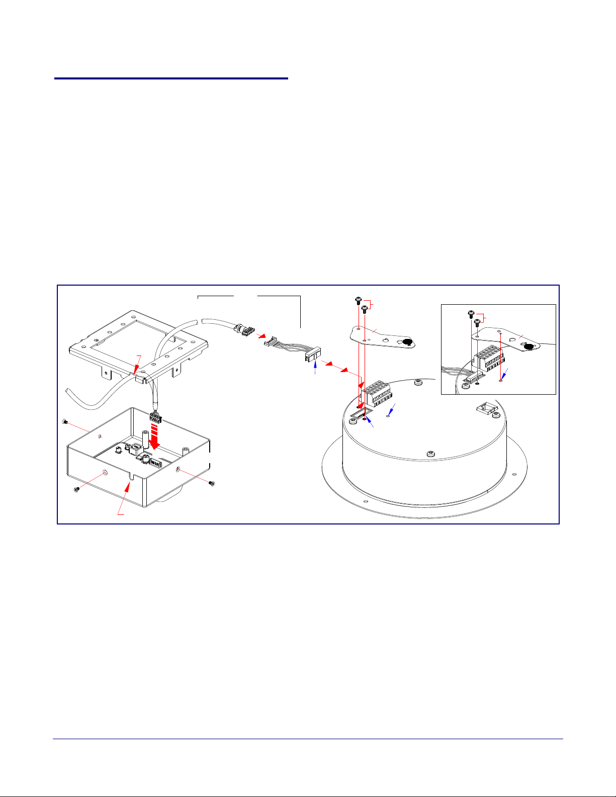
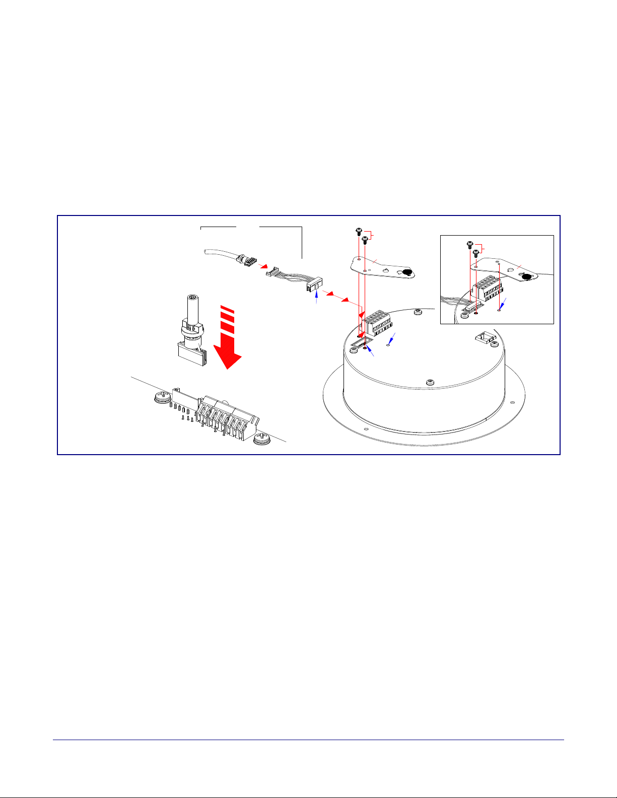
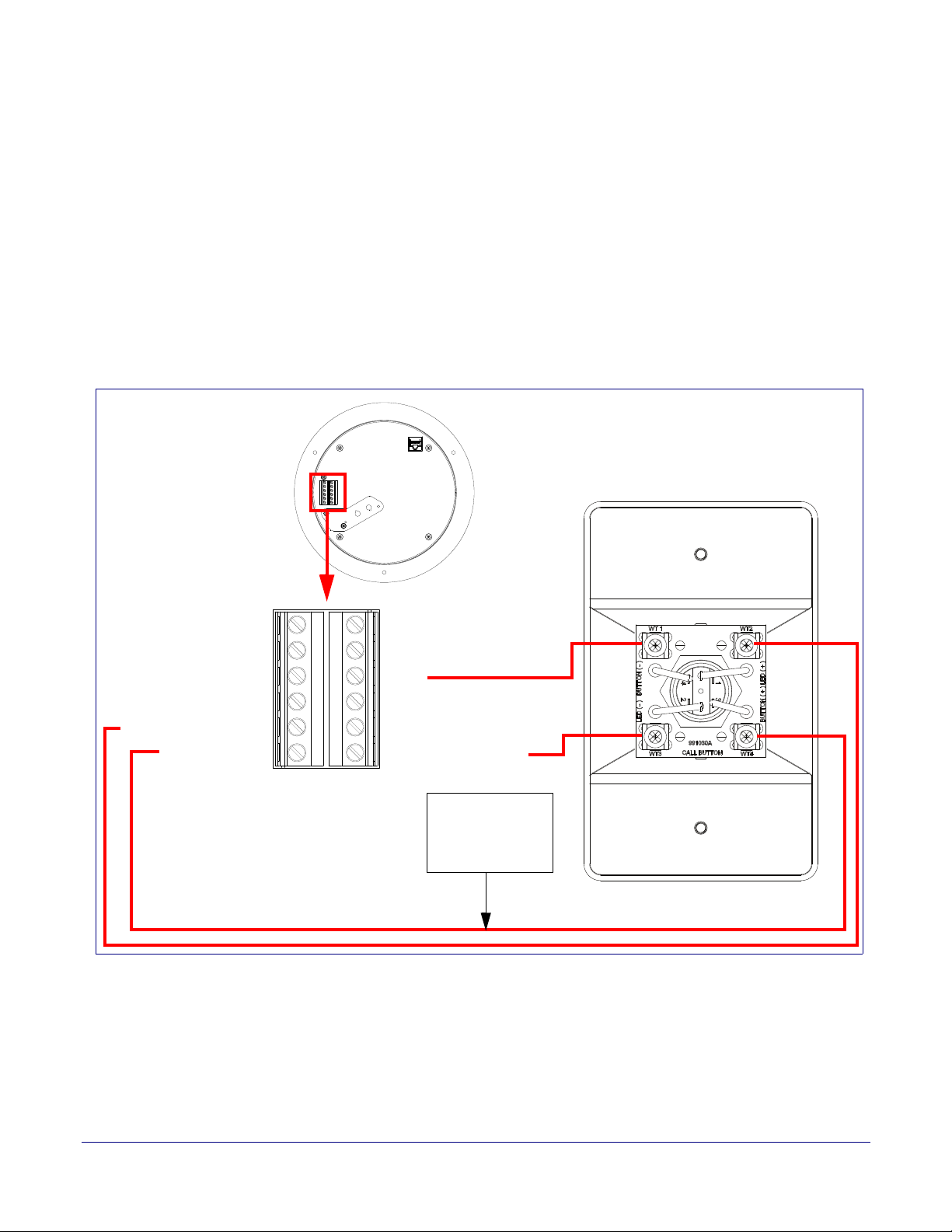
2.2.2.3 Running the SIP Talk-Back Speaker with a Remote Call Button
Note Figure 2-3 shows the optional 011185 Remote Call Button (sold separately). See Section
1.9.1, "Optional 011185 Remote Call Button (sold separately)"
In Figure 2-3, the optional Remote Call Button (sold separately) enables calls to the SIP Talk-Back
Speaker that can be initiated or answered from a remotely-mounted switch. When enabled through
the web interface, if the Remote Call Button is pressed, the speaker would initiate a SIP call to a
predetermined extension.
When the SIP Talk-Back Speaker is called from a remote phone and Auto-Answer is not enabled
within the unit’s Web interface, the LED on the Remote Button will blink. The call will be answered
when the button is pressed.
Figure 2-6. Running the Speaker with a Remote Call Button
Device Configuration
19
Operations Guide 931191I CyberData Corporation
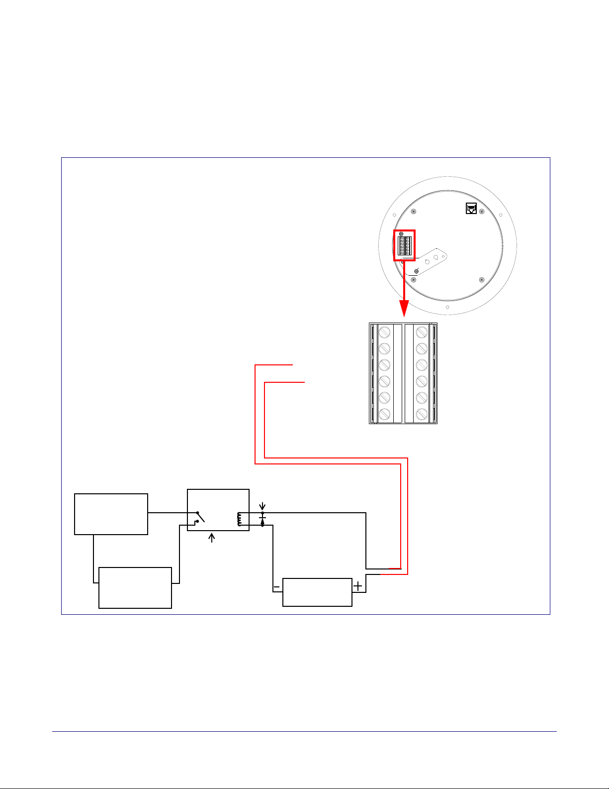
2.2.2.4 SIP Talk-Back Speaker with an External Device
AUX SPEAKER (-)
AUX SPEAKER (+)
GND
LINE OUT (-)
LINE OUT (+)
BUTTON LED (-)
BTN SENSE
BUTTON LED (+)
RELAY NO
RELAY COM
AUX POWER (-)
AUX POWER (+)
(+24VDC @ 1A)
J10
J9
CLASS II WIRING
High PIV Ultrafast
Switching Diode
Output Contacts
AC or DC-rated
depending upon
controlled device
requirements
DC Power Supply
(Max. 30 VDC @ 1A)
Solid State or
Mechanical Relay
AC or DC
Power Source as
required by an
external device
IN
OUT
External device
such as an electric
door strike or LED
strobe light
Speaker
In Figure 2-7, when the SIP Talk-Back Speaker is called from a remote phone, the relay on the
speaker can be programmed to drive an external device such as an alert strobe. This external device
may also be addressed from a separate Unified Communication (UC) server.
Figure 2-7. Speaker with an External Device
Installing the SIP Talk-Back Speaker
Device Configuration
20
Operations Guide 931191I CyberData Corporation

2.2.2.5 SIP Talk-Back Speaker with Auxiliary Speaker Connection
GENERAL ALERT
8 Ohm Auxiliary Speaker
High-purity copper
16-gauge wire and
a maximum length
of 20 feet
Speaker
(Part #011120, RAL 9002)
*When using the second speaker connection,
the analog volume control needs to be disabled.
*Because of the limitations of PoE power,
when running the Speaker with a second auxiliary
speaker, the analog or digital volume level setting
must not exceed a setting of 6.
(Part #011121, RAL 9003)
AUX SPEAKER (-)
AUX SPEAKER (+)
GND
LINE OUT (-)
LINE OUT (+)
+5V OUT
RELAY NO
RELAY COM
AUX POWER (-)
AUX POWER (+)
(+24VDC @ 1A)
J10
J9
N/C
N/C
CLASS II WIRING
In Figure 2-8, the SIP Talk-Back Speaker supports an amplified audio output for a second analog
speaker. While the total speaker wattage is the same, by connecting a low cost analog speaker,
a
dditional coverage can be realized
Caution
Operational Note: The SIP speaker dynamically adjusts volume to properly
budget power when accessories are connected. For best performance, it is
recommended that either an 802.3AT or 24V auxiliary power source is used
when connecting an auxiliary speaker and a clock kit.
Figure 2-8. SIP Talk-Back Speaker with Auxiliary Speaker Connection
Installing the SIP Talk-Back Speaker
Device Configuration
21
Operations Guide 931191I CyberData Corporation
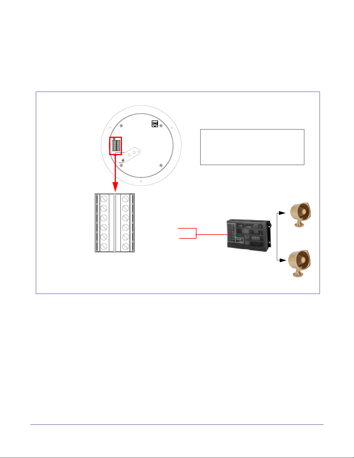
2.2.2.6 SIP Talk-Back Speaker with Line Out
AUX SPEAKER (-)
AUX SPEAKER (+)
GND
LINE OUT (-)
LINE OUT (+)
BUTTON LED (-)
BTN SENSE
BUTTON LED (+)
RELAY NO
RELAY COM
AUX POWER (-)
AUX POWER (+)
(+24VDC @ 1A)
J10
J9
CLASS II WIRING
Office area in Factory
Factory Floor
Amplifier
Line Out:
Output Signal Amplitudes 2.0 VPP maximum
Output Level +2dBm nominal
Total Harmonic Distortion 0.5% maximum
Output Impedance 10k ohm
Speaker
In Figure 2-9, for areas that require more speaker volume, the SIP Talk-Back Speaker can be
connected directly to an auxiliary amplifier to drive additional horns or speakers. This is done
through the line-out connection.
Figure 2-9. SIP Talk-Back Speaker with Line Out
Installing the SIP Talk-Back Speaker
Device Configuration
22
Operations Guide 931191I CyberData Corporation
 Loading...