

CyberData 011324 Installation Quick Reference
Quick Reference 931154D © 2016, CyberData Corporation, ALL RIGHTS RESERVED
© 2016, CyberData Corporation, ALL RIGHTS RESERVED 931154D Quick Reference
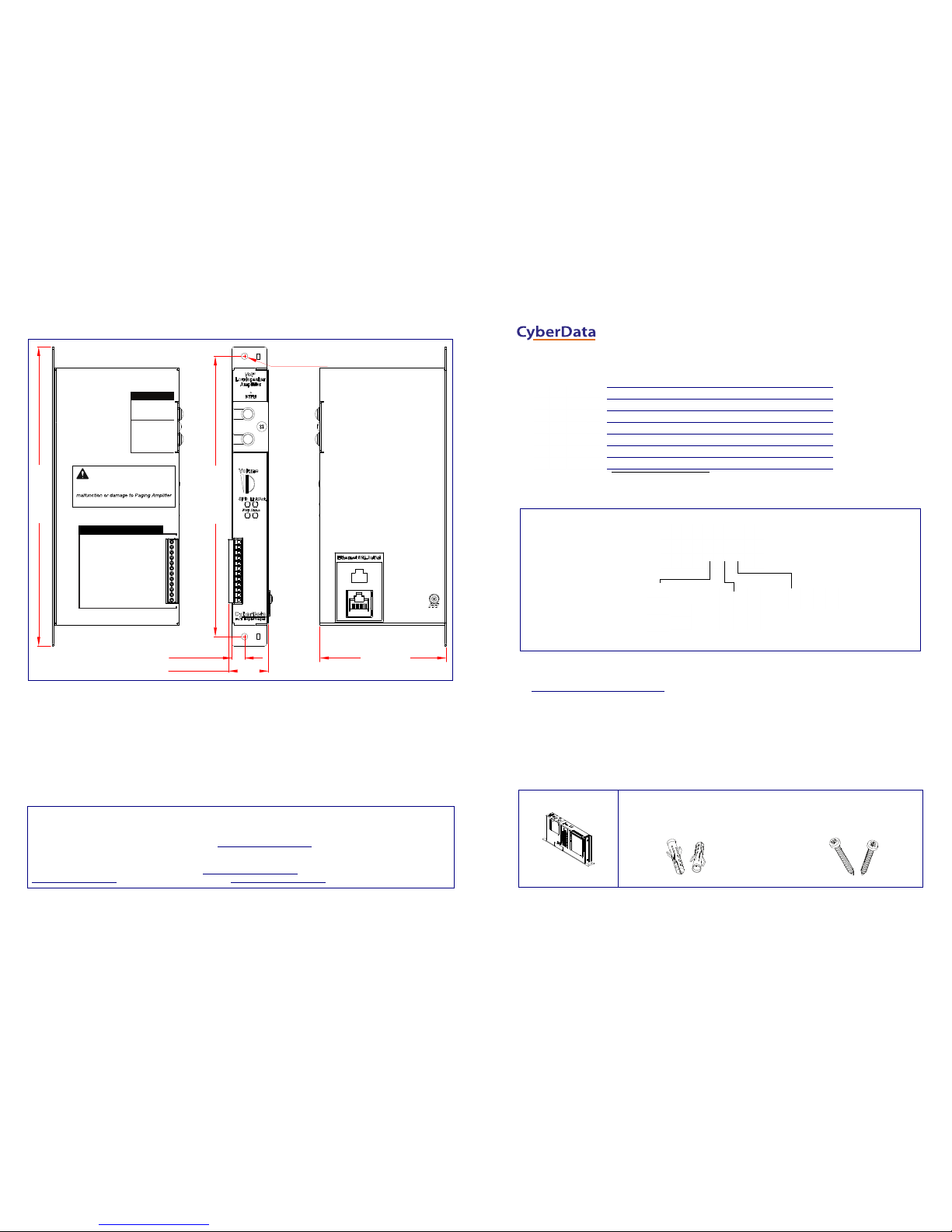
Dimensions
Contacting CyberData
5
4
3
2
1
3
2
1
CLASS II WIRING
MIC IN
STROBE
www.cyberdata.net
Mono(+)/Left Spkr (+) - 12
Left Spkr (-) - 11
Right Spkr (+) - 10
Mono(-)/Right Spkr (-) - 9
Line-Out (+) - 8
Line-Out (-) - 7
Line-In (-) - 6
Line-In (+) - 5
Relay COM - 4
Relay NO/NC - 3
Door Sense/Button Common (GND) - 2
Door Sense/Button Contact (+) - 1
SAFETY WARNING!
Please read the owner’s manual for proper
installation. Incorrect wiring can lead to
and/or other attached components.
CLASS II WIRING
1.042 [26.5]
0.326 [8.3]
7.303 [185.5]
3.295 [83.7]
7.795 [198.0]
Dimensions are in Inches [Millimeter]
ø0.172 [ø4.4]
(2 Places)
Sales: (831) 373-2601 ext. 334
Support: 831-373-2601 ext. 333
Support Website: http://support.cyberdata.net/
RMA Department: (831) 373-2601 ext. 136
RMA Email: RMA@CyberData.net
RMA Status: http://support.cyberdata.net/
Warranty Information: http://support.cyberdata.net/
Corporate Headquarters
CyberData Corporation
3 Justin Court
Monterey, CA 93940, USA
Phone: 831-373-2601
Fax: 831-373-4193
http://www.cyberdata.net/
Typical System Installation
Getting Started
• Download the Operations Guide PDF file from the Documents tab at the following webpage:
http://www.cyberdata.net/voip/011324/
• Create a plan for the locations of your paging amplifiers.
• WARNING: This product should be installed by a licensed electrician according to all local electrical and building codes.
• WARNING: To prevent injury, this appar atus must be securely attached to the floor/wall in accordance with the installation
instructions.
• WARNING: The PoE connector is intended for intra-building connections only and does not route to the outside plant.
• WARNING: The SIP Paging Amplifier enclosure is not rated for any AC voltages!
Parts
Parameter Factory Default Setting
IP Addressing DHCP
IP Address
a
a. Default if there is not a DHCP server present.
10.10.10.10
Web Access Username admin
Web Access Password admin
Subnet Mask
a
255.0.0.0
Default Gateway
a
10.0.0.1
*See the Operations Guide for more
installation options.
Compliant Non-PoE Ethernet Switch
VoIP Phone
IP-PBX Server
SIP Paging Amplifier
(1) Screw Accessory Kit
(2) Plastic Ribbed Anchors (2) #6x1.25" Pan Head
Phillips Sheet Metal Screw
(1) Assembly
The IP Endpoint Company
Installation Quick Reference
SIP Paging Amplifier
011324
VoIPon www.voipon.co.uk sales@voipon.co.uk Tel: (0)330 088 0195 Fax: +44 (0)1245 808299
Quick Reference 931154D © 2016, CyberData Corporation, ALL RIGHTS RESERVED© 2016, CyberData Corporation, ALL RIGHTS RESERVED 931154D Quick Reference
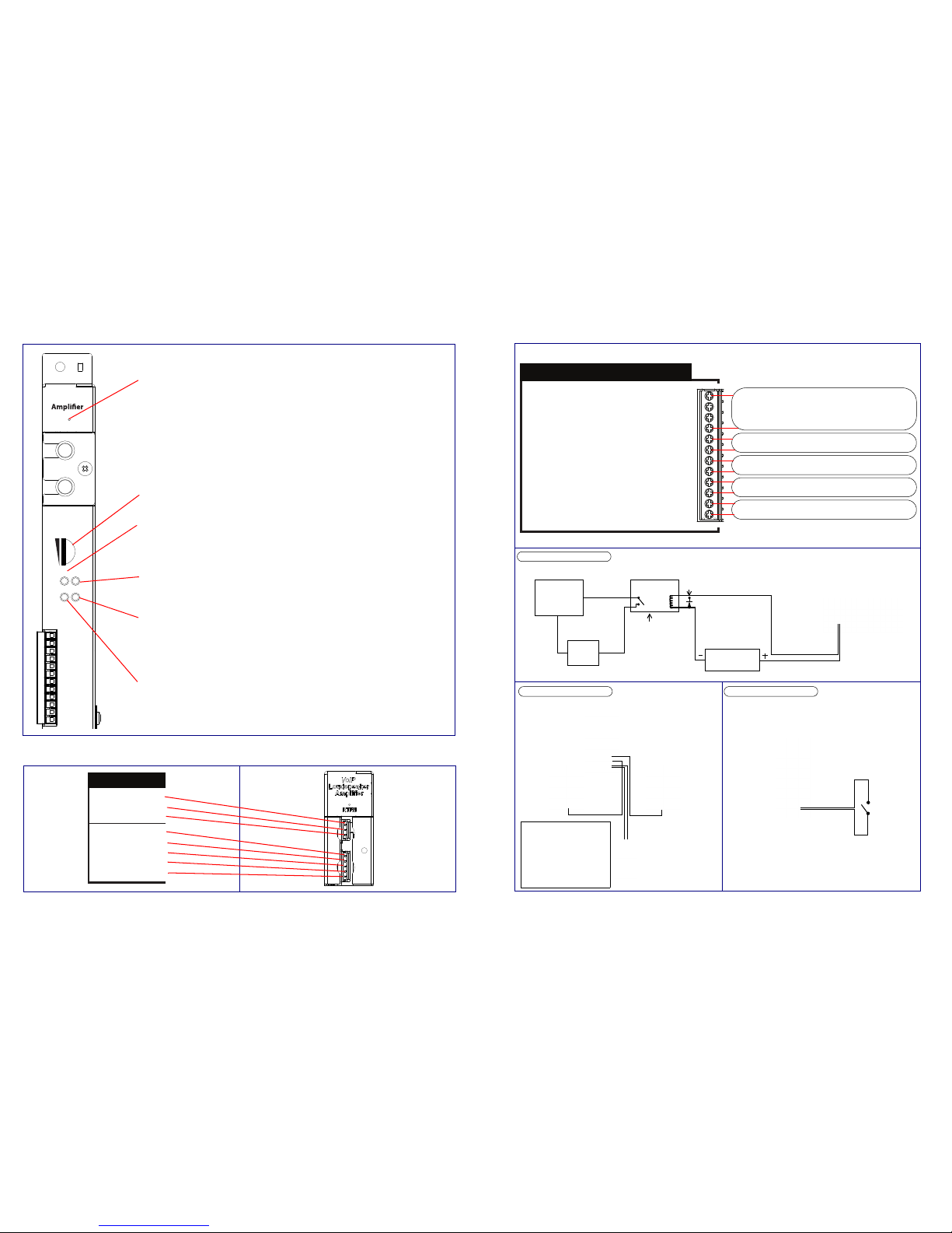
Features
Strobe Connections
SPD Link/Act.
PWR Status
Volume
RTFM
VoIP
Loudspeaker
Speaker Volume
Speed (SPD) LED (AMBER)
The Speed (SPD) LED illuminates AMBER for a 100Mb link
or is off for a 10MB link when the network link to the device is established.
Status LED (GREEN)
The GREEN Status LED illuminates after supplying power to the device.
Link/Activity (Link/Act.) LED (GREEN)
The
GREEN Link/Activity (Link/Act.) LED blinks to indicate network traffic.
Power (PWR) LED (GREEN/BLUE)
The Power (PWR) LED is GREEN in low power mode (
802.3af)
and BLUE during high power mode (802.3at).
RTFM Switch
To broadcast the de vice’s current IP address, press and hold the RTFM switch for a couple
of seconds and then release it.
To restore the factory defaults, complete the following steps:
1. Press and hold the RTFM switch until you hear the device announce the words,
“restoring defaults” and “rebooting”.
2. Release the RTFM switch. The device will be restored to the factory default settings.
*See the Operations Guide for more information about the features in this section.
5
4
3
2
1
3
2
1
CLASS II WIRING
MIC IN
STROBE
*See the Operations
Guide for more
information about
the connections in
this section.
Connection Options
Mono(+)/Left Spkr (+) - 12
Left Spkr (-) - 11
Right Spkr (+) - 10
Mono(-)/Right Spkr (-) - 9
Line-Out (+) - 8
Line-Out (-) - 7
Line-In (-) - 6
Line-In (+) - 5
Relay COM - 4
Relay NO/NC - 3
Door Sense/Button Common (GND) - 2
Door Sense/Button Contact (+) - 1
CLASS II WIRING
Speaker Connections*
Line-Out Connection (10K Ohm)
Line-In Connection
Relay Connection
Sensor Connection
Line-In Connection
Sensor Connection
Relay Connection
High PIV Ultrafast
Switching Diode
Output Contacts
AC or DC-rated
depending upon
controlled device
requirements
DC Power Supply
(Max. 30 VDC @ 1A)
Solid State or
Mechanical
Relay
AC or DC
Power
Source
IN
OUT
External device
such as an
electric door strike
or an LED strobe
light
When line-in is enabled on
the device, the audio
received from the line-in
connection will be played
to the speaker(s) and lineout connection as the
lowest priority audio.
Music Source
Paging Amplifier
*See the Operations Guide for diagrams and
information about the connections in this section.
Paging Amplifier
Paging Amplifier
VoIPon www.voipon.co.uk sales@voipon.co.uk Tel: (0)330 088 0195 Fax: +44 (0)1245 808299
 Loading...