

Page 1
Quick Reference 930613E © 2014, CyberData Corporation, ALL RIGHTS RESERVED© 2014, CyberData Corporation, ALL RIGHTS RESERVED 930613E Quick Reference
The IP Endpoint Company
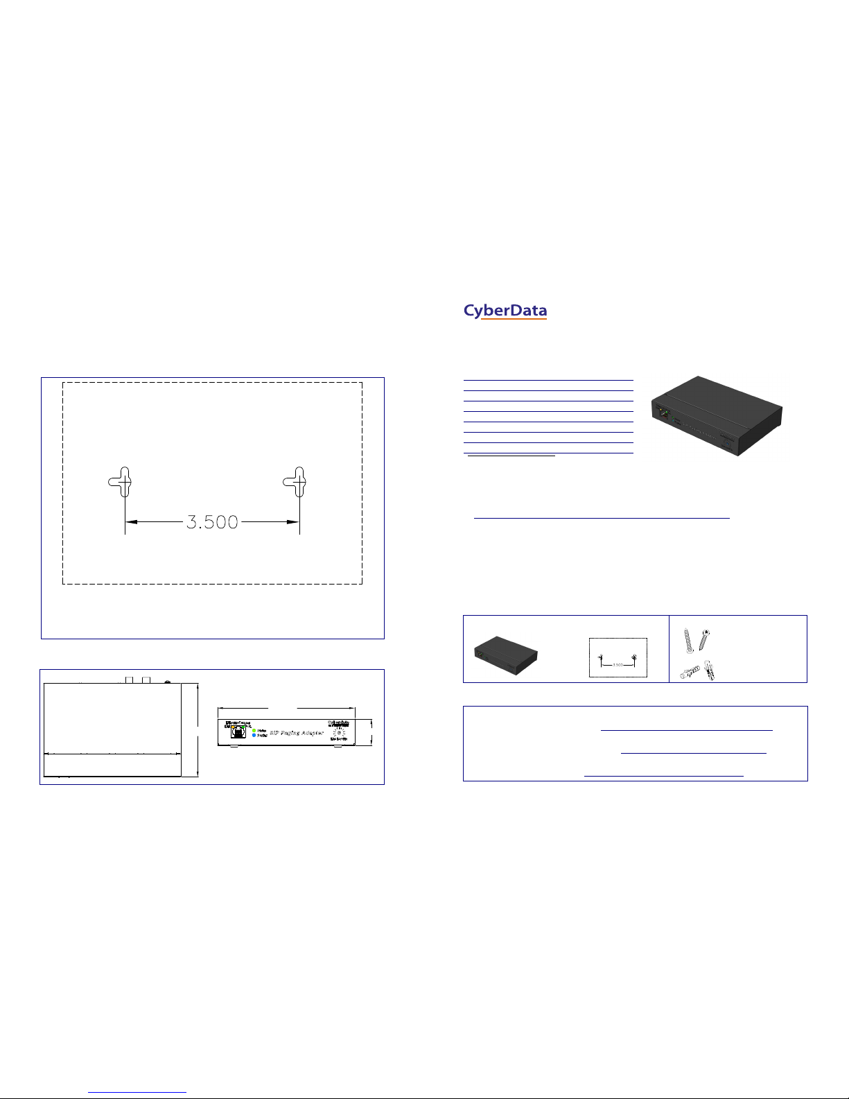
Mounting
Dimensions
You have the option to use the following mounting template to mark, and then drill two 3/16-inch (0.1875-inch) holes for
the mounting anchors.
To install and mount the SIP Paging Adapter:
1. Install the mounting anchors in the holes, and position the SIP Paging Adapter mounting holes over the anchors.
2. Use the two #6 sheet metal screws to secure the SIP Paging Adapter onto the mounting surface.
Drill Hole Size for Anchor Installation: 3/16-inch (0.1875-inch)
Dimensions are in Inches [Millimeter]
4.1 [104.0]
6.0 [152.4]
1.2 [29.6]
Dimensions are in Inches [Millimeters]
Getting Started
• Be sure that you have received all the parts described in the Parts List section.
• Download the Operations Guide at the following website:
http://www.cyberdata.net/products/voip/legacyanalog/sippagingadapter/docs.html
• WARNING: This product should be installed by a licensed electrician according to all local electrical and building
codes.
• WARNING: To prevent injury, this apparatus must be securely attached to the floor/wall in accordance with the
installation instructions.
• WARNING: The PoE connector is intended for intra-building connections only and does not route to the outside
plant.
• WARNING: This enclosure is not rated for any AC voltages!
Parts List
Contacting CyberData
Parameter Factory Default Setting
IP Addressing DHCP
IP Address
a
a. Default if there is not a DHCP server present.
10.10.10.10
Web Access Username admin
Web Access Password admin
Subnet Mask
a
255.0.0.0
Default Gateway
a
10.0.0.1
(1) Mounting Kit
(1) SIP Paging Adapter
(1) Mounting Template
(2) #6 x1.25-inch, PanHead,
Phillips Sheet Metal Screw
(2) Plastic Anchors
(see the last page)
Sales: (831) 373-2601 ext. 334
Support: 831-373-2601 ext. 333
Web: http://www.cyberdata.net/support/contactsuppor tvoip.php
RMA Dept: (831) 373-2601 ext. 136
Email: [email protected]
RMA Status: http://www.cyberdata.net/support/rmastatus.html
Warranty and RMA information is available at the following website:
http://www.cyberdata.net/support/warranty/index.html
Corporate Headquarters
CyberData Corporation
3 Justin Court
Monterey, CA 93940, USA
Phone: 831-373-2601
Fax: 831-373-4193
www.CyberData.net
Installation Quick Reference
SIP Paging Adapter
SIP Compliant
011233
Page 2
© 2014, CyberData Corporation, ALL RIGHTS RESERVED 930613E Quick Reference Quick Reference 930613E © 2014, CyberData Corporation, ALL RIGHTS RESERVED
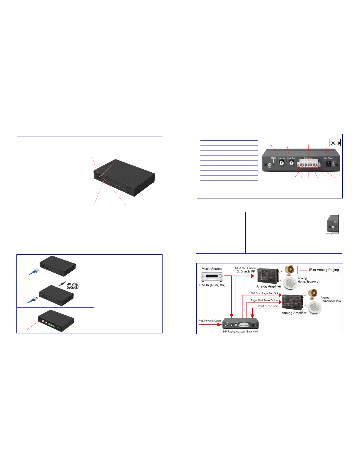
Connections
RTFM Switch
Typical Configuration
Pin 1 Pin2 Pin 3 Pin 4 Pin 5
RCA Line In RCA Line Out Power
Page Port Output Connections
Pin Description
1 Fault Sense Input (Common)
2 Fault Sense Input (Sense)
3 Positive 600-Ohm Audio Output
a
a. The 600-Ohm audio output of the
page port is also suited for interfaces
with lower input impedances.
4 Negative 600-Ohm Audio Output
a
5 Audio Ground Reference
6 Relay Contact - Common
b
b. 1 Amp at 30 VDC for continuous loads
7 Relay Contact - Normally Open
b
Page Port Output
Pin 6 Pin 7
48VDC
RTFM Switch
To restore the factory default settings:
1. Press and hold the RTFM switch while all the indicator
lights turn off.
2. Continue to press the switch until after the indicator lights
turn back on, and then release the switch.
Note: The “Restoring Defaults” announcement can be
heard if a speaker or amplified speaker is connected to the
unit.
3. All SIP Paging Adapter settings are restored to the
factory defaults, and the unit reboots.
To announce the IP address:
1. Briefly press and then quickly
release the RTFM switch.
Note: The IP address announcement
can be heard if a speaker or amplified
speaker is connected to the unit.
Verifying Operations and Settings
Setting Up the SIP Paging Adapter
When you plug in the Ethernet cable or power supply:
•The GREEN/BLUE Status LED and the
GREEN Paging LED both blink at a rate of
10 times per second during the initial network
setup.
• The round, GREEN/BLUE Status LED on the
front of the SIP Paging Adapter comes on
indicating that the power is on. Once the device
has been initialized, this LED blinks at one
second intervals.
• The square, GREEN/AMBER Link LED above
the Ethernet port indicates that the network
connection has been established. The Link LED
changes color to confirm the auto-negotiated
connection speed:
• The Link LED is GREEN at 10 Mbps.
• The Link LED is AMBER at 100 Mbps.
• The GREEN Paging LED comes on after the
device is booted and initialized. This LED
blinks when a page is in progress. You can
disable Beep on Initialization on the Device
Configuration page.
Status
(GREEN/BLUE LED)
Paging
(GREEN LED)
Link
(GREEN/AMBER LED)
Activity
(GREEN LED)
To set up the SIP Paging Adapter, connect the
device to your network:
PoE
•For PoE , plug one end of an 802.3af Ethernet
cable into the SIP Paging Adapter Ethernet
port. Plug the other end of the Ethernet cable
into your network. See the figure on the left.
Non-PoE
•For Non-PoE, connect the SIP Paging Adapter
to a 48VDC power supply. See the figure on
the left.
Chassis Ground
• If required, connect the earth grounding wire to
the Chassis Ground. See the figure on the
left.
Chassis ground
Chassis Ground
PoE
Non PoE with 48 VDC Power Supply
 Loading...