

Page 1

The IP Endpoint Company
VoIP Singlewire-enabled
Push-to-Talk Speaker
Operations Guide
011182, RAL 9002, Gray White, Standard
011183, RAL 9003, Signal White, Optional
Document Part #930463C
for Firmware Version 3.0.1
Part Number
CyberData Corporation
3 Justin Court
Monterey, CA 93940
(831) 373-2601
Page 2

VoIP Singlewire-enabled Push-to-Talk Speaker Operations Guide 930463C
Technical Support
The fastest way to get technical support for your VoIP product is to
submit a VoIP Technical Support form at the following website:
http://support.cyberdata.net/
Phone: (831) 373-2601, Ext. 333
Email: [email protected]
Fax: (831) 373-4193
Company and product information is at www.cyberdata.net.
The IP Endpoint Company
Part #
011182, RAL 9002, Gray White, Standard
011183, RAL 9003, Signal White, Optional
COPYRIGHT NOTICE:
© 2015, CyberData Corporation, ALL RIGHTS RESERVED.
This manual and related materials are the copyrighted property of CyberData Corporation. No part of
this manual or related materials may be reproduced or transmitted, in any form or by any means
(except for internal use by licensed customers), without prior express written permission of
CyberData Corporation. This manual, and the products, software, firmware, and/or hardware
described in this manual are the property of CyberData Corporation, provided under the terms of an
agreement between CyberData Corporation and recipient of this manual, and their use is subject to
that agreement and its terms.
DISCLAIMER: Except as expressly and specifically stated in a written agreement executed by
CyberData Corporation, CyberData Corporation makes no representation or warranty, express or
implied, including any warranty or merchantability or fitness for any purpose, with respect to this
manual or the products, software, firmware, and/or hardware described herein, and CyberData
Corporation assumes no liability for damages or claims resulting from any use of this manual or such
products, software, firmware, and/or hardware. CyberData Corporation reserves the right to make
changes, without notice, to this manual and to any such product, software, firmware, and/or
hardware.
OPEN SOURCE STATEMENT: Certain software components included in CyberData products are
subject to the GNU General Public License (GPL) and Lesser GNU General Public License (LGPL)
“open source” or “free software” licenses. Some of this Open Source Software may be owned by third
parties. Open Source Software is not subject to the terms and conditions of the CyberData
COPYRIGHT NOTICE or software licenses. Your right to copy, modify, and distribute any Open
Source Software is determined by the terms of the GPL, LGPL, or third party, according to who
licenses that software.
Software or firmware developed by CyberData that is unrelated to Open Source Software is
copyrighted by CyberData, subject to the terms of CyberData licenses, and may not be copied,
modified, reverse-engineered, or otherwise altered without explicit written permission from
CyberData Corporation.
TRADEMARK NOTICE: CyberData Corporation and the CyberData Corporation logos are
trademarks of CyberData Corporation. Other product names, trademarks, and service marks may be
the trademarks or registered trademarks of their respective owners.
CyberData Corporation 930463C Operations Guide
Page 3

Revision History
Revision 930463C, which corresponds to firmware version 3.0.1, was released on August 19, 2015,
and has the following changes:
• Adds the following feature to Section 1.3, "Product Features":
• Supports SingleWire/Informacast Server Resilience
• Updates Figure 2-12, "Home Page"
• Updates Figure 2-14, "Firmware Upgrade Page"
• Updates Figure 2-15, "Reboot System Section"
Operations Guide 930463C CyberData Corporation
Page 4
Important Safety Instructions
GENERAL ALERT
GENERAL ALERT
1. Read these instructions.
2. Keep these instructions.
3. Heed all warnings.
4. Follow all instructions.
5. Do not use this apparatus near water.
6. Clean only with dry cloth.
7. Do not block any ventilation openings. Install in accordance with the manufacturer’s instructions.
8. Do not install near any heat sources such as radiators, heat registers, stoves, or other apparatus
(including amplifiers) that produce heat.
9. Do not defeat the safety purpose of the polarized or grounding-type plug. A polarized plug has
two blades with one wider than the other. A grounding type plug has two blades and a third
grounding prong. The wide blade or the third prong are provided for your safety. If the provided
plug does not fit into your outlet, consult an electrician for replacement of the obsolete outlet.
10. Protect the power cord from being walked on or pinched particularly at plugs, convenience
receptacles, and the point where they exit from the apparatus.
11. Only use attachments/accessories specified by the manufacturer.
12. Refer all servicing to qualified service personnel. Servicing is required when the apparatus has
been damaged in any way, such as power-supply cord or plug is damaged, liquid has been
spilled or objects have fallen into the apparatus, the apparatus has been exposed to rain or
moisture, does not operate normally, or has been dropped.
13. Prior to installation, consult local building and electrical code requirements.
Warn in g
Electrical Hazard: This product should be installed by a licensed electrician
according to all local electrical and building codes.
Warn in g
Electrical Hazard: To prevent injury, this apparatus must be securely attached to
the floor/wall in accordance with the installation instructions.
CyberData Corporation 930463C Operations Guide
Page 5
Pictorial Alert Icons
GENERAL ALERT
Hazard Levels
Danger: Indicates an imminently hazardous situation which, if not avoided, will result in death or
serious injury. This is limited to the most extreme situations.
Warning: Indicates a potentially hazardous situation which, if not avoided, could result in death or
serious injury.
General Alert
This pictoral alert indicates a potentially hazardous situation. This alert will be
followed by a hazard level heading and more specific information about the
hazard.
Ground
This pictoral alert indicates the Earth grounding connection point.
Caution: Indicates a potentially hazardous situation which, if not avoided, could result in minor or
moderate injury. It may also alert users against unsafe practices.
Notice: Indicates a statement of company policy (that is, a safety policy or protection of property).
The safety guidelines for the equipment in this manual do not purport to address all the safety issues
of the equipment. It is the responsibility of the user to establish appropriate safety, ergonomic, and
health practices and determine the applicability of regulatory limitations prior to use. Potential safety
hazards are identified in this manual through the use of words Danger, Warning, and Caution, the
specific hazard type, and pictorial alert icons.
CyberData Corporation 930463C Operations Guide
Page 6

Abbreviations and Terms
Abbreviation or Term Definition
A-law A standard companding algorithm, used in European digital
communications systems to optimize, i.e., modify, the dynamic range of an
analog signal for digitizing.
AVP Audio Video Profile
Cat 5 TIA/EIA-568-B Category 5
DHCP Dynamic Host Configuration Protocol
LAN Local Area Network
LED Light Emitting Diode
Mbps Megabytes per Second.
NTP Network Time Protocol
PBX Private Branch Exchange
PoE Power over Ethernet (as per IEEE 802.3af standard)
RTP Real-time Transport Protocol
RTFM Reset Test Function Management
Talkback Two-way communication enabled
TFTP Trivial File Transfer Protocol
u-law A companding algorithm, primarily used in the digital telecommunication
UC Unified Communications
VoIP Voice over Internet Protocol
CyberData Corporation 930463C Operations Guide
Page 7

Contents
Chapter 1 Product Overview 1
1.1 How to Identify This Product .....................................................................................................2
1.2 Installation ................................................................................................................................3
1.3 Product Features ......................................................................................................................3
1.4 Supported Protocols .................................................................................................................4
1.5 Product Specifications ..............................................................................................................4
1.6 Dimensions ...............................................................................................................................5
1.7 Starting a Push-to-Talk Session from an IP Phone (Summary) ...............................................6
1.8 Starting a Push-to-Talk Session from a Push-to-Talk Speaker (Summary) ..............................6
1.9 Starting a Push-to-Talk Session from an IP Phone (Detailed) ..................................................7
1.10 Starting a Push-to-Talk Session from a Push-to-Talk Speaker (Detailed) ............................14
Chapter 8 Installing the Singlewire-enabled Speaker 20
2.1 Parts List ................................................................................................................................20
2.2 Set Up and Test the Speaker ..................................................................................................21
2.3 Configure the Speaker Parameters .......................................................................................33
2.4 Configuring the Clock .............................................................................................................37
2.5 Upgrade the Firmware and Reboot the Singlewire-enabled Speaker ....................................39
2.6 Identifying and Testing a Ceiling Speaker when Using InformaCast 8.1 or Later ...................44
i
2.2.1 Connect Power to the Speaker .....................................................................................22
2.2.5 Installation Options .......................................................................................................25
2.2.9 Confirm that the Speaker is Operational and Linked to the Network ..........................28
2.2.12 Confirm the IP Address, Test the Audio, and Check the Volume ...............................29
2.2.14 Adjust the Volume ......................................................................................................30
2.2.15 Using the Microphone ................................................................................................31
2.2.16 How to Set the Factory Default Settings .....................................................................32
2.3.1 Singlewire-enabled Speaker Web Page Navigation .....................................................34
2.3.2 Log in to the Configuration Home Page .......................................................................35
2.5.2 Reboot the Singlewire-enabled Speaker ......................................................................42
Appendix A Mounting the Speaker 50
A.1 Mount the Speaker ................................................................................................................50
Appendix B Troubleshooting/Technical Support 53
B Frequently Asked Questions (FAQ) ...........................................................................................53
B Documentation ..........................................................................................................................53
B.1 Contact Information ................................................................................................................54
B.2 Warranty and RMA Information ..............................................................................................54
Index 55
Operations Guide 930463C CyberData Corporation
Page 8
1 Product Overview
GENERAL ALERT
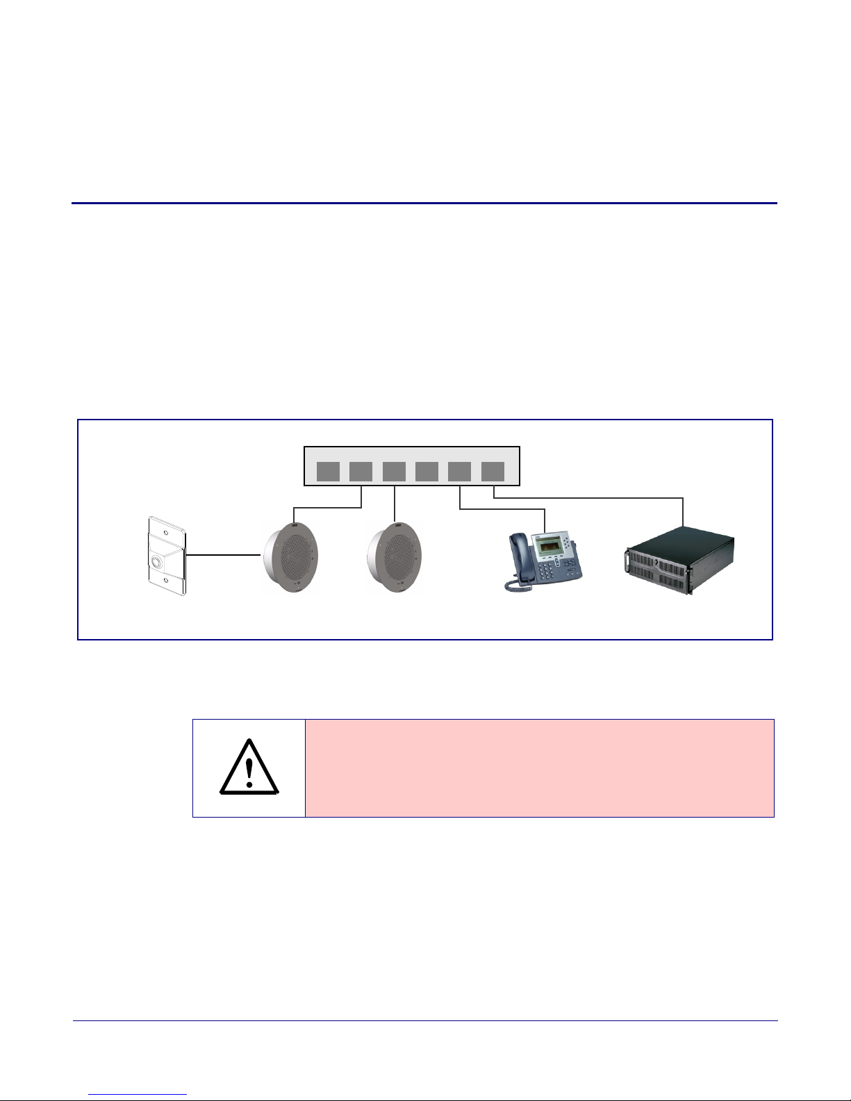
802.3af Compliant Ethernet Switch
IP Phone
12 34 56
IP Talkback InformaCast ServerIP SpeakerRemote Call Button
Speaker
The CyberData Singlewire-enabled Push-to-Talk speaker enables two-way conversations using the
Singlewire Push-to-Talk application running on the phone. The Singlewire-enabled Speaker easily
connects into local area networks with a single CAT5/6 cable from your PoE switch. Its small footprint
allows the speaker to be mounted almost anywhere with multiple mounting options available.
By use of the optional remote call button, calls to a predetermined extension can be initiated from
t
he room with the speaker. During the active calls, the LED light on the switch can be programmed to
blink to show call activity.
Figure 1-1 illustrates a typical configurations for the Singlewire-enabled Speaker.
Figure 1-1. Typical Installation
1
Note The vers
Note Prio
Operations Guide 930463C CyberData Corporation
r to installation, create a plan for the locations of your speakers.
ion of InformaCast needs to be 4.0 or higher.
General Alert
Consult local building and electrical code requirements prior to installation.
Page 9
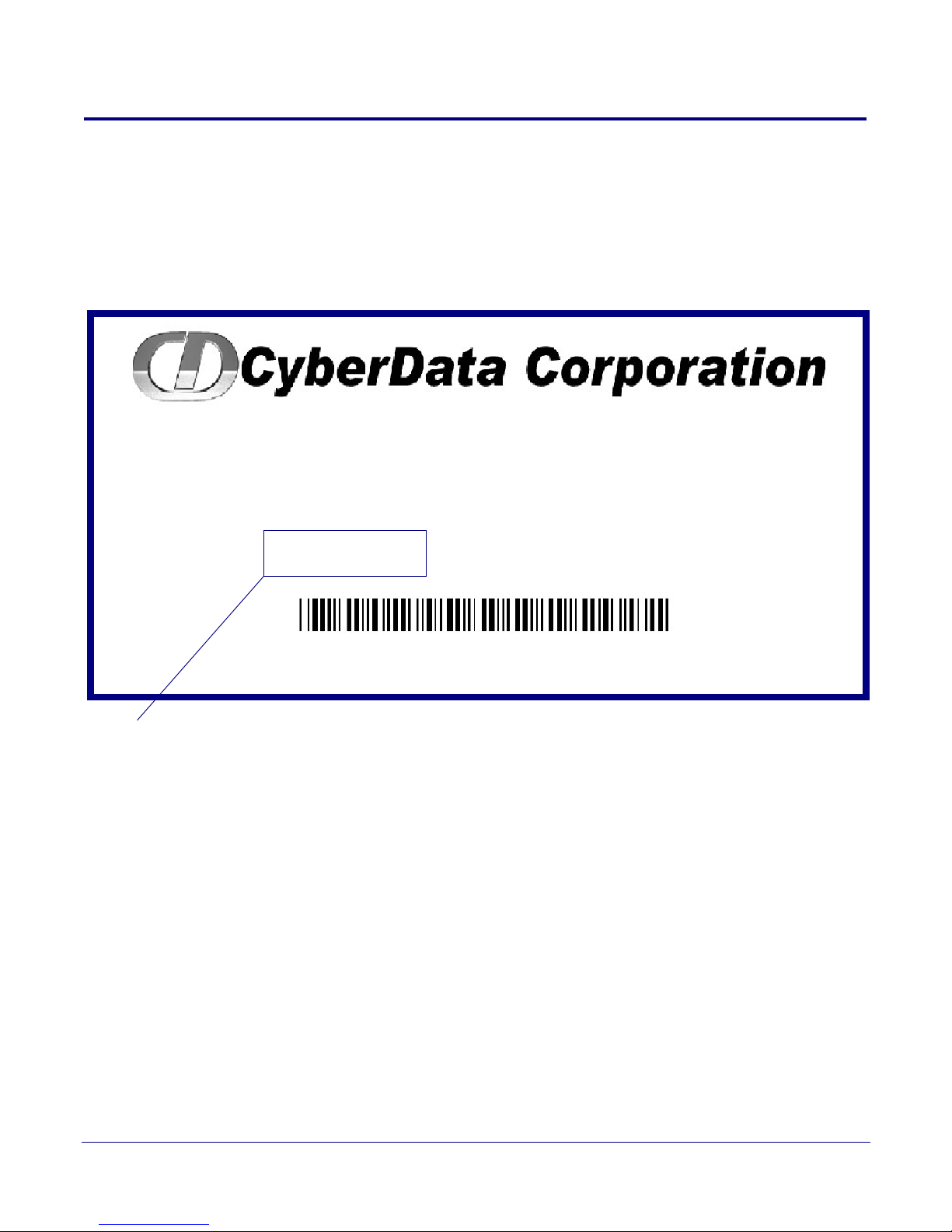
1.1 How to Identify This Product
SPEAKER,V2 SINGLEWIRE PTT,
CEILING/WALL MNT,RAL9002,RoHS
011182A / 021037G
Model number
WWW.CYBERDATA.NET
182000001
To identify the VoIP Singlewire-enabled Push-to-Talk Speaker, look for a model number label similar
to the one shown in
• 011182, RAL 9002, Gray White, Standard Color
• 011183, RAL 9003, Signal White, Optional Color
Figure 1-2. The model number on the label should be one of the following:
Figure 1-2. Model Number Label
Product Overview
How to Identify This Product
2
Operations Guide 930463C CyberData Corporation
Page 10
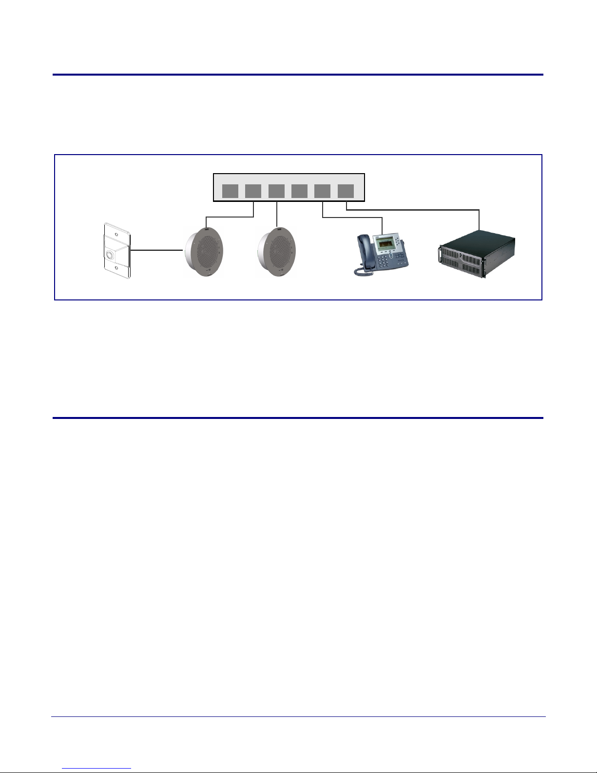
1.2 Installation
802.3af Compliant Ethernet Switch
IP Phone
12 34 56
Speaker InformaCast ServerSpeakerRemote Call Button
Figure 1-3 illustrates a typical configurations for the Singlewire-enabled Speaker.
See the following sections for other installation options:
• Section 2.2.4, "Running the Singlewire-enabled Speaker with Auxiliary Power"
• Section 2.2.6, "Singlewire-enabled Speaker with Remote Call Button"
• Section 2.2.7, "Singlewire-enabled Speaker with Extra Speaker Connection"
• Section 2.2.8, "Singlewire-enabled Speaker with Line Out"
Figure 1-3. Typical Installation
Product Overview
Installation
3
1.3 Product Features
• Push-to-Talk
• Informacast-controlled operation
• Supports SingleWire/Informacast Server Resilience
• Web-based configuration
• Web-based firmware upgradeable
• Small footprint
• High efficiency speaker driver
• PoE 802.3af Enabled (Powered-over-Ethernet)
• Network and external speaker volume control
• Optional external call button and LED indicator
Operations Guide 930463C CyberData Corporation
Page 11

1.4 Supported Protocols
The Singlewire-enabled Speaker supports:
• Multicast
• DHCP Client
Dynamically assigns IP addresses in addition to the option to use static addressing.
• InformaCast Version 4.0 and greater
• TFTP Client
Facilitates Web-based firmware upgrades of the latest speaker capabilities.
•RTP
• Audio Encodings
PCMU (G.711 mu-law)
PCMA (G.711 A-law)
Packet Time 20 ms
Product Overview
Supported Protocols
4
1.5 Product Specifications
Category Specification
Sensitivity 96dB/1W/1M S.P. Level
Output 10 Watts Peak Power
Operating temperature -30 to 55 C (-22 to 131 F)
Port baud rate 10/100 Mbps
Protocol Singlewire InformaCast 4.0 and higher
Power Input PoE 802.3af (as per IEEE 802.3af standard from a UL listed power source)
Payload types G711, A-law and µ-law
Regulatory compliance FCC Class B, CE
Warranty 2 years limited
Dimensions 9” x 2.4”
Weight 2.8 lbs./shipping weight of 3.8 lbs.
(1.3 kg/shipping weight of 1.7 kg)
Part number 011182, RAL 9002, Gray White, Standard Color
011183, RAL 9003, Signal White, Optional Color
Operations Guide 930463C CyberData Corporation
Page 12
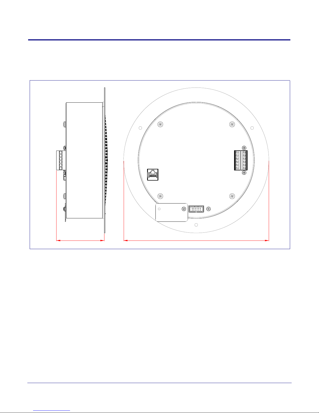
1.6 Dimensions
9.0 [229]
3.0 [75]
Dimensions are in Inches [Millimeter]
Figure 1-4 shows the dimensions for the Singlewire-enabled Speaker.
Figure 1-4. Dimensions
Product Overview
Dimensions
5
Operations Guide 930463C CyberData Corporation
Page 13

Product Overview
Starting a Push-to-Talk Session from an IP Phone (Summary)
1.7 Starting a Push-to-Talk Session from an IP Phone
(Summary)
To start a push-to-talk session from an IP phone:
1. Make sure that the Cisco environment is set it up with the Intercom Service.
2. On the Cisco IP phone, select the Service button.
3. Select the Informacast Intercom Service.
4. On the Cisco IP phone, dial the extension number for the Speaker that you want to call.
5. When the call from the Cisco IP phone to the Speaker is active, you can do one of the following:
• Select the Listen button on the phone to listen to someone talking into the Speaker.
• Select the Ta lk button on the phone to talk to someone listening to the Speaker.
Note The IP phone always controls the talking and listening feature of the Speaker.
6. Select the Exit button to terminate the call.
6
Note For a more detailed explanation of this procedure with pictures, see Section 1.9, "Starting a
Push-to-Talk Session from an IP Phone (Detailed)".
1.8 Starting a Push-to-Talk Session from a Push-to-Talk
Speaker (Summary)
To start a push-to-talk session from a push-to-talk speaker:
1. Make sure that the Cisco environment is set it up with the Intercom Service.
2. Press the Remote Call Button to make the Singlewire-enabled Speaker dial a pre-programmed
IP phone extension.
3. When the call from the Singlewire-enabled Speaker to the Cisco IP phone is active, you can do
one of the following:
• Select the Listen button on the phone to listen to someone talking into the Speaker.
• Select the Ta lk button on the phone to talk to someone listening to the Speaker.
Note The IP phone always controls the talking and listening feature of the Speaker.
4. Select the Exit button to terminate the call.
Note For a more detailed explanation of this procedure with pictures, see Section 1.10, "Starting a
Push-to-Talk Session from a Push-to-Talk Speaker (Detailed)".
Operations Guide 930463C CyberData Corporation
Page 14

Product Overview
Services buttonInformacast Intercom service Button under Select in the phone window
Starting a Push-to-Talk Session from an IP Phone (Detailed)
1.9 Starting a Push-to-Talk Session from an IP Phone
(Detailed)
To start a Push-to-Talk Session from an IP Phone:
1. Press the Services button. In the Phone window, you will see the words Informacast Intercom
listed under Services.
2. Press the button under the word Select in the phone window.
Figure 2. Select the Informacast Intercom Service
7
Operations Guide 930463C CyberData Corporation
Page 15

Product Overview
Speaker Selection
Button under Select in the phone window
Starting a Push-to-Talk Session from an IP Phone (Detailed)
3. When the words Speaker Selection and Dial Code appear in the phone window, use the
keypad to enter the dial code for the preconfigured Push-to-Talk speaker that you want to call.
4. After entering the dial code, press the button under the word Submit in the phone window to call
the speaker.
Figure 3. Enter the Dial Code
8
Operations Guide 930463C CyberData Corporation
Page 16

Product Overview
Talking to “Speaker Name”
Starting a Push-to-Talk Session from an IP Phone (Detailed)
5. When the words Talking to “Speaker Name” appear in the phone window, the speaker is in
Talking Mode. A person at the speaker can begin talking to the phone.
Figure 4. Talking Mode
9
Operations Guide 930463C CyberData Corporation
Page 17
Product Overview
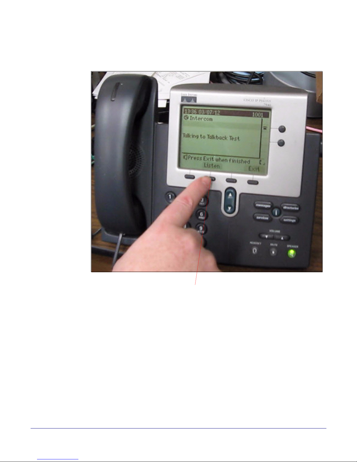
Button under Listen in the phone window
Starting a Push-to-Talk Session from an IP Phone (Detailed)
6. If you want to switch the speaker to Listening Mode, the person at the phone must press the
button under the word Listen that is in the phone window.
Figure 5. Press the Listen Button to Switch to Listening Mode
10
Operations Guide 930463C CyberData Corporation
Page 18
Product Overview
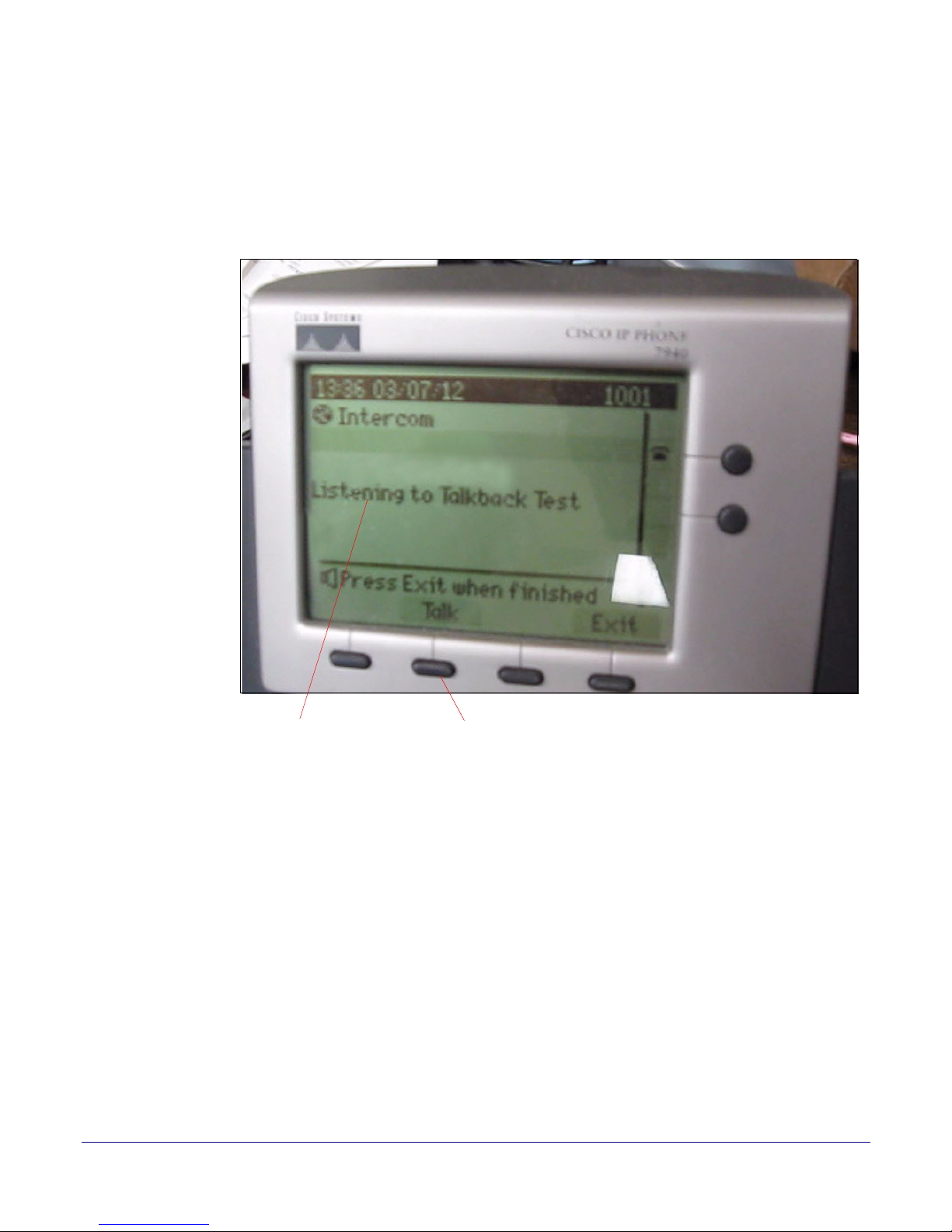
Listening to “Speaker Name” Button under Talk in the phone window
Starting a Push-to-Talk Session from an IP Phone (Detailed)
7. When the words Listening to “Speaker Name” appear in the phone window, the speaker is in
Listening Mode. A person at the speaker can begin listening to someone talking through the
phone.
8. If you want to switch the speaker back to Talking Mode, the person at the phone must press the
button under the word Tal k that is in the phone window.
Figure 6. Listening Mode
11
Operations Guide 930463C CyberData Corporation
Page 19
Product Overview
Button under Exit in the phone window
Starting a Push-to-Talk Session from an IP Phone (Detailed)
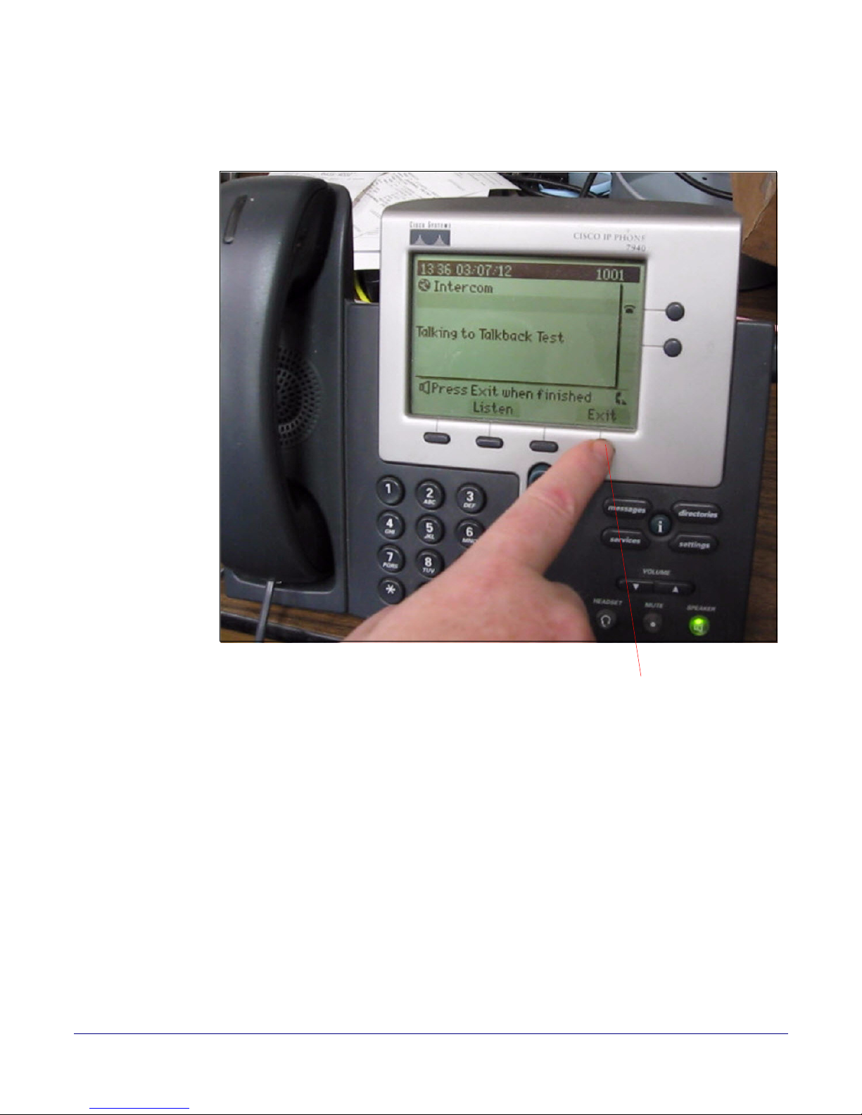
9. To end the call at any time, the person at the phone must press the button under the word Exit in
the phone window.
Figure 7. Press Exit to End to End the Call
12
Operations Guide 930463C CyberData Corporation
Page 20
Product Overview
Button under Exit in the phone window
Starting a Push-to-Talk Session from an IP Phone (Detailed)
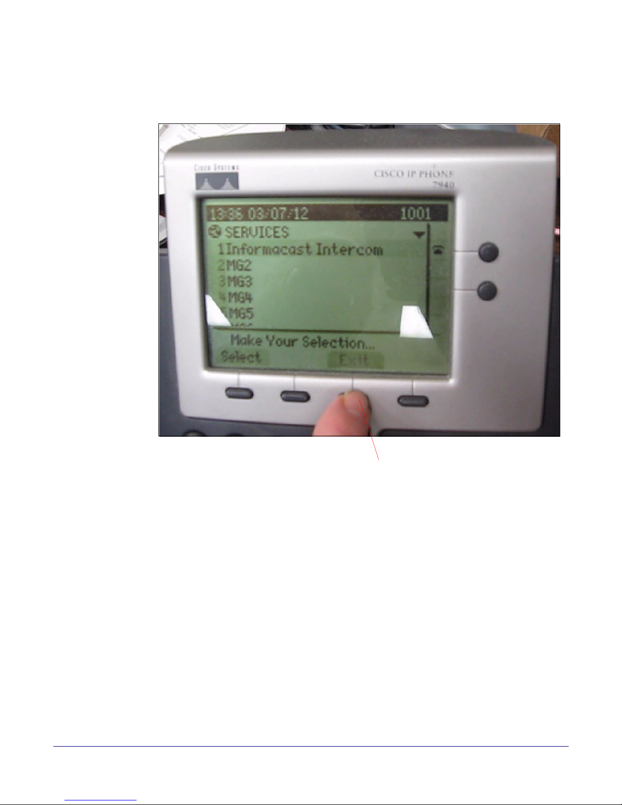
10. The person at the phone must then press the button under the word Exit in the phone window
again to return to the Home screen.
Figure 8. Press Exit Again to Return to the Home Screen
13
Operations Guide 930463C CyberData Corporation
Page 21
Product Overview
Remote Call Button
Starting a Push-to-Talk Session from a Push-to-Talk Speaker (Detailed)
1.10 Starting a Push-to-Talk Session from a Push-to-Talk
Speaker (Detailed)
To start a Push-to-Talk Session from a Push-to-Talk Speaker:
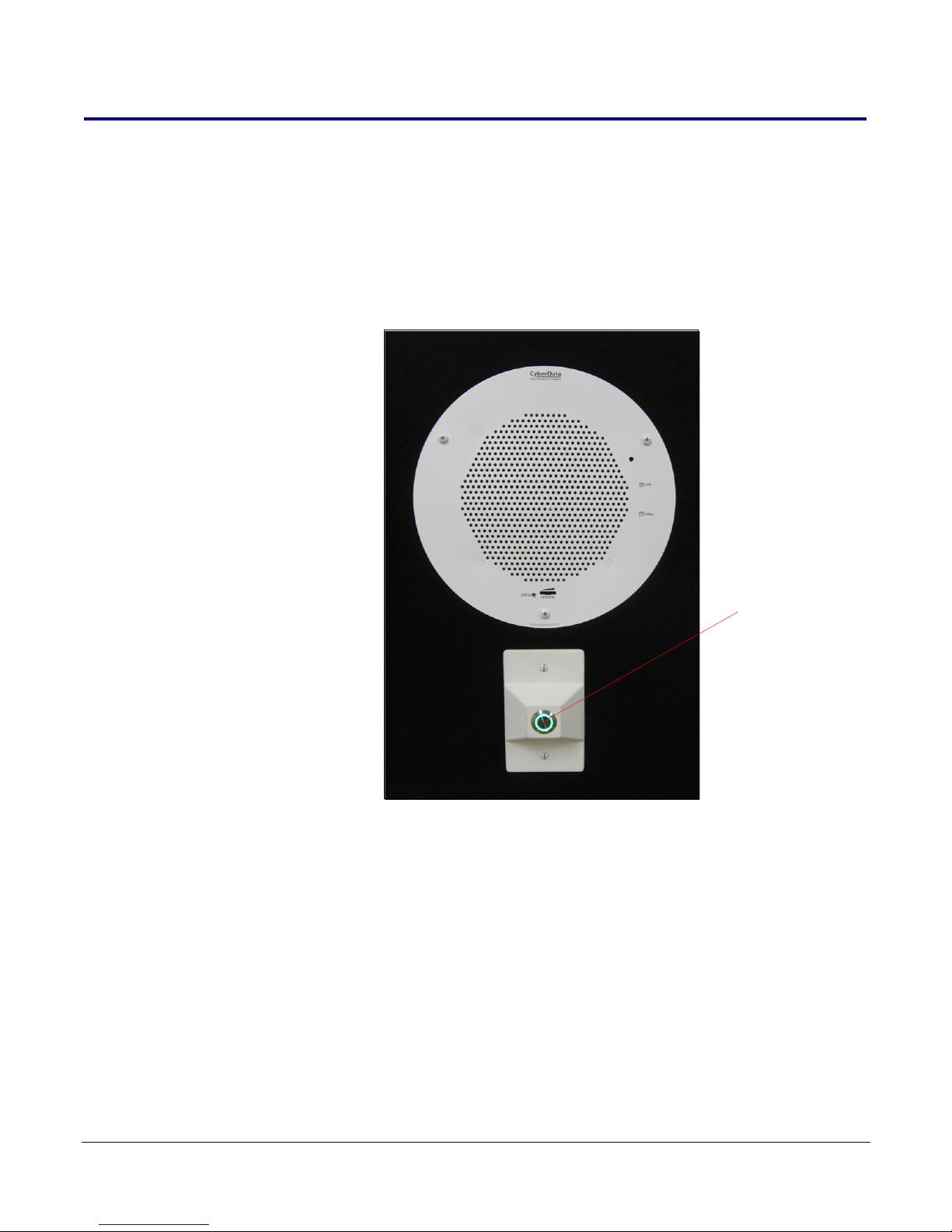
1. The person at the preconfigured Push-to-Talk speaker must press the Remote Call Button. The
speaker will immediately call a specific IP phone.
Figure 9. Press the Remote Call Button
14
Operations Guide 930463C CyberData Corporation
Page 22
Product Overview
Talking to Talkback Test
Starting a Push-to-Talk Session from a Push-to-Talk Speaker (Detailed)
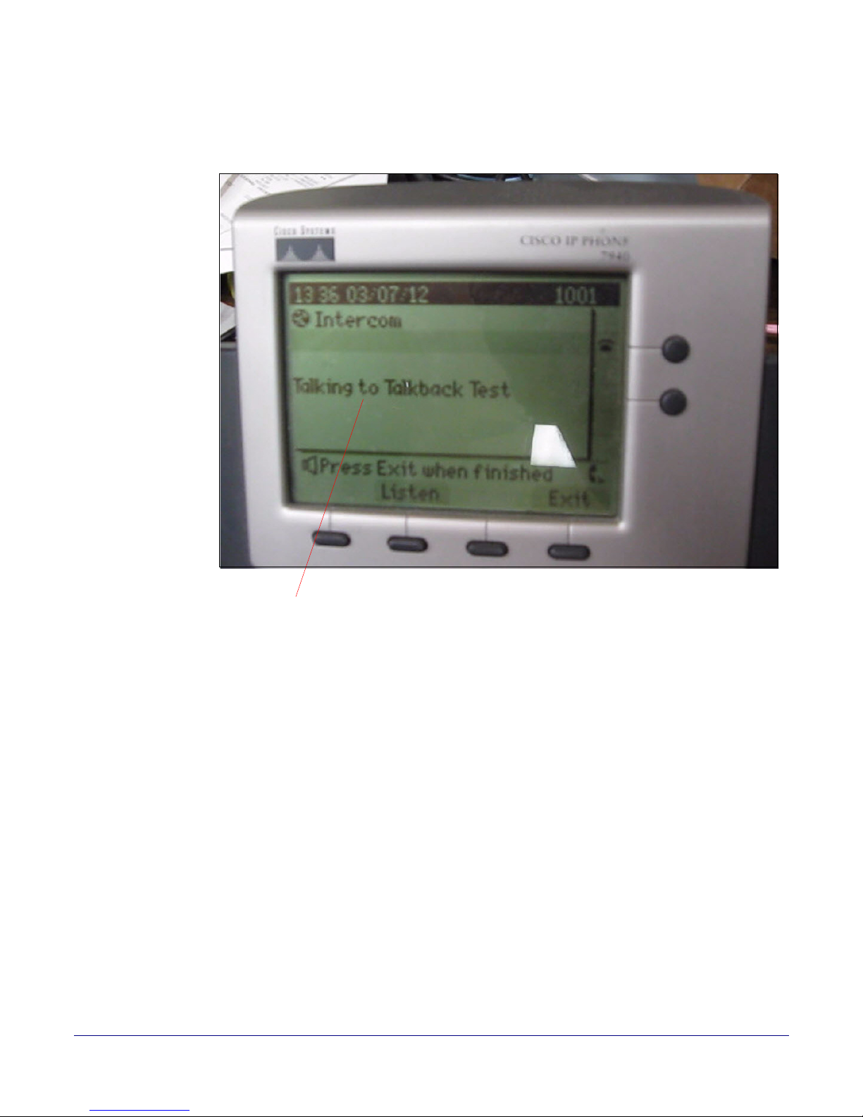
2. When the words Talking to Talkback Test appear in the phone window, the speaker is in
Talking Mode. A person at the speaker can begin talking to the phone.
Figure 10. Talking Mode
15
Operations Guide 930463C CyberData Corporation
Page 23
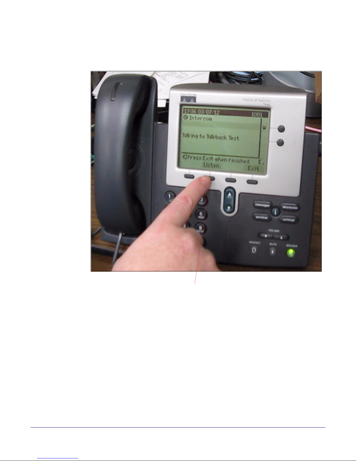
Product Overview
Button under Listen in the phone window
Starting a Push-to-Talk Session from a Push-to-Talk Speaker (Detailed)
3. If you want to switch the speaker to Listening Mode, the person at the phone must press the
button under the word Listen that is in the phone window.
Figure 11. Press the Listen Button to Switch to Listening Mode
16
Operations Guide 930463C CyberData Corporation
Page 24
Product Overview
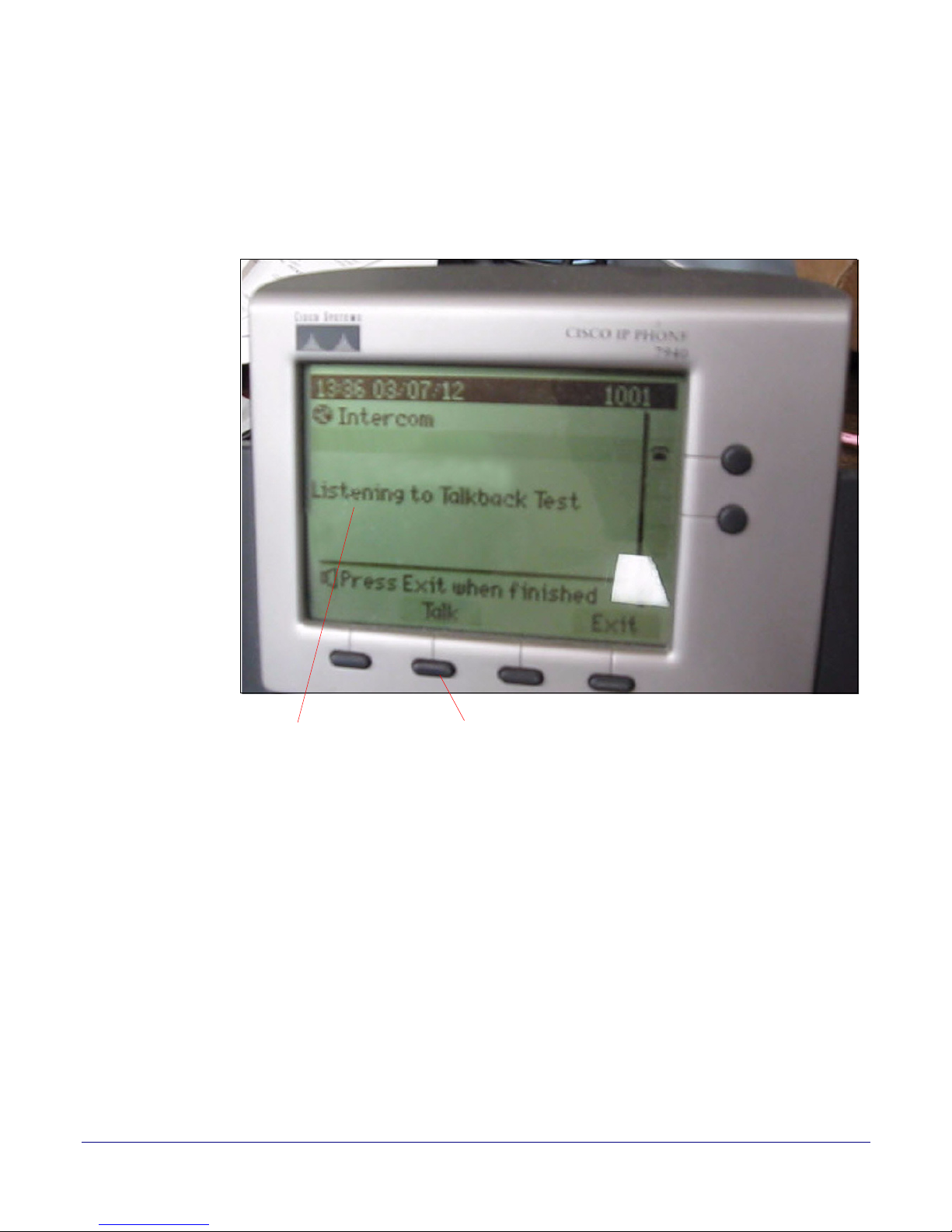
Listening to Talkback Test Button under Talk in the phone window
Starting a Push-to-Talk Session from a Push-to-Talk Speaker (Detailed)
4. When the words Listening to Talkback Test appear in the phone window, the speaker is in
Listening Mode. The person at the speaker can begin listening to someone talking through the
phone.
5. If you want to switch the speaker back to Talking Mode, the person at the phone must press the
button under the word Tal k that is in the phone window.
Figure 12. Listening Mode
17
Operations Guide 930463C CyberData Corporation
Page 25
Product Overview
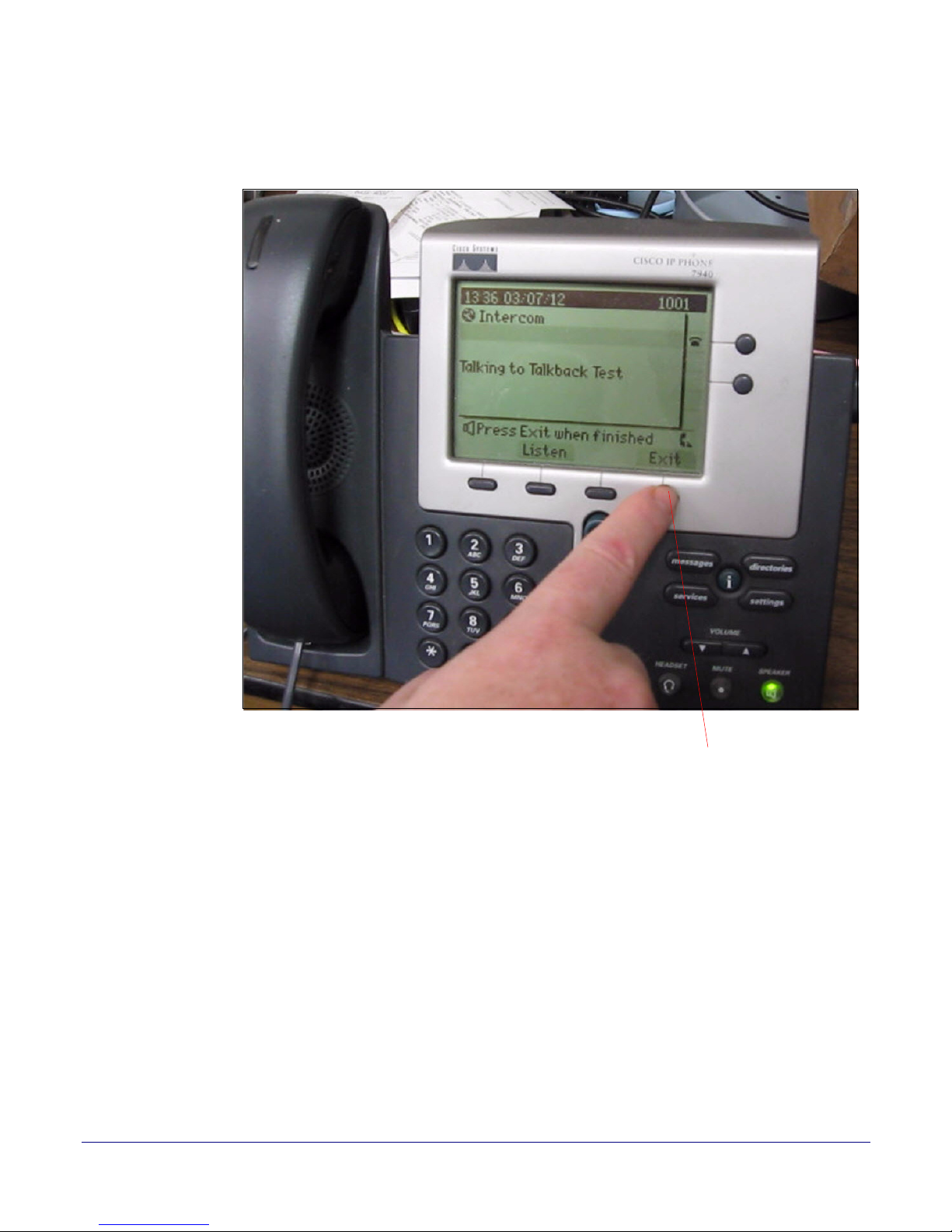
Button under Exit in the phone window
Starting a Push-to-Talk Session from a Push-to-Talk Speaker (Detailed)
6. To end the call at any time, the person at the phone must press the button under the word Exit in
the phone window.
Figure 13. Press Exit to End to End the Call
18
Operations Guide 930463C CyberData Corporation
Page 26
Product Overview
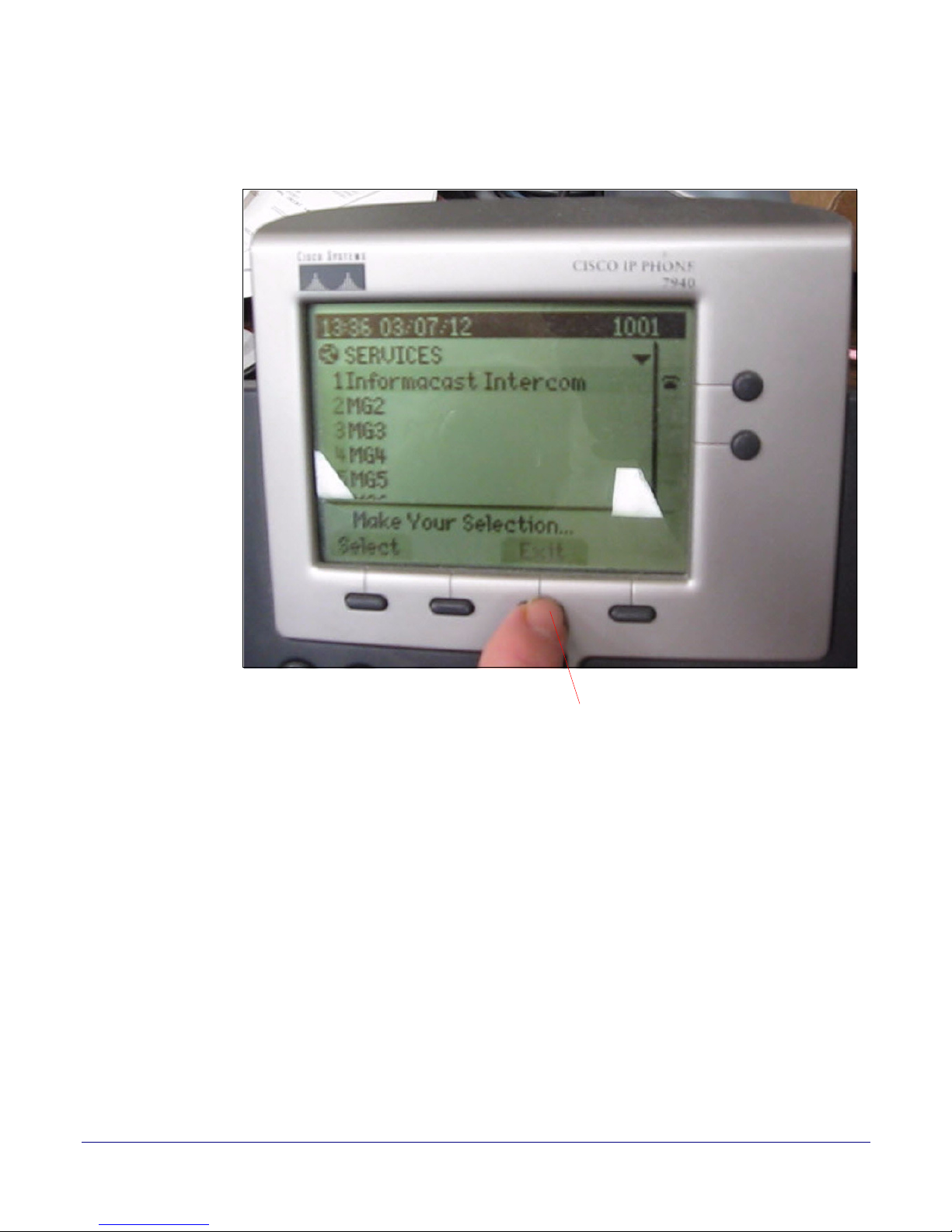
Button under Exit in the phone window
Starting a Push-to-Talk Session from a Push-to-Talk Speaker (Detailed)
7. The person at the phone must then press the button under the word Exit in the phone window
again to return to the Home screen.
Figure 14. Press Exit Again to Return to the Home Screen
19
Operations Guide 930463C CyberData Corporation
Page 27
8 Installing the Singlewire-enabled Speaker
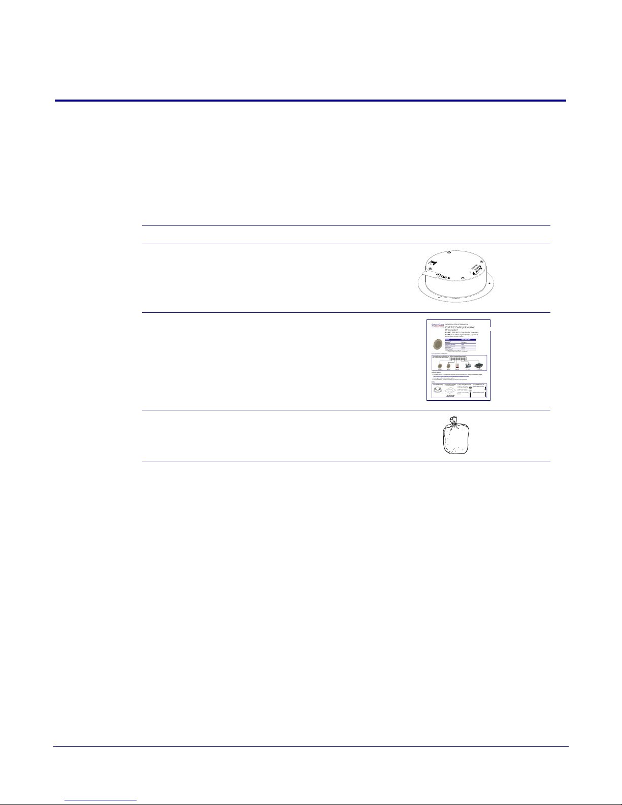
2.1 Parts List
Ta bl e 2-1 illustrates the parts for each speaker and includes kits for the drop ceiling and drywall
mounting.
20
Note The installation template for the Singlewire-enabled Speaker is lo
Quick Reference Guide that is included in the packaging with each speaker.
Table 2-1. Parts
Quantity Part Name Illustration
1 Singlewire-enabled Speaker Assembly
1 Installation Quick Reference Guide
1 Speaker Mounting Accessory Kit
(P
art #070054A)
cated on the Installation
Operations Guide 930463C CyberData Corporation
Page 28

2.2 Set Up and Test the Speaker
Set up and configure each speaker before you mount it.
CyberData delivers each speaker with the following factory default values:
Table 2-2. Factory Network Default Settings—Default of Network
Parameter Factory Default Setting
IP Addressing DHCP
IP Address
Web Access Username admin
Web Access Password admin
Subnet Mask
Default Gateway
a
a
a
a. Default if there is not a DHCP server present.
10.10.10.10
255.0.0.0
10.0.0.1
Installing the Singlewire-enabled Speaker
Set Up and Test the Speaker
21
Operations Guide 930463C CyberData Corporation
Page 29
Installing the Singlewire-enabled Speaker
802.3af Switch Class “0”
Cat 5 Ethernet cable
Speaker
2.2.1 Connect Power to the Speaker
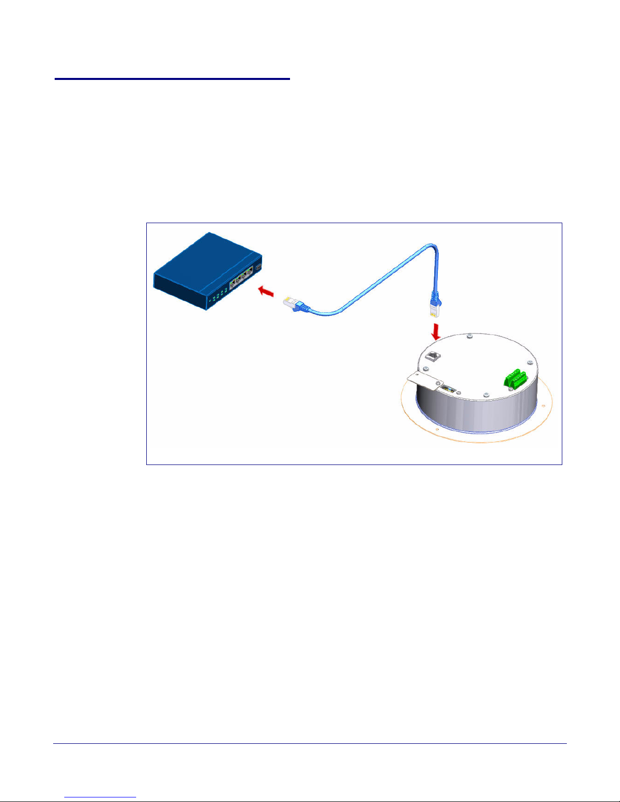
Figure 2-1 through Figure 2-3 illustrates how to connect power to the Singlewire-enabled Speaker.
2.2.2 Singlewire-enabled Speaker to a 802.3af Compliant PoE Switch
Figure 2-1 illustrates how to connect the Singlewire-enabled Speaker to a 802.3af compliant PoE
switch via a Cat 5 Ethernet cable.
Figure 2-1. Singlewire-enabled Speaker to a 802.3af Compliant PoE Switch
Set Up and Test the Speaker
22
Operations Guide 930463C CyberData Corporation
Page 30
Installing the Singlewire-enabled Speaker
PoE Injector (Part #010867A)
Non PoE Switch
Speaker
Cat 5 Ethernet cable
Set Up and Test the Speaker
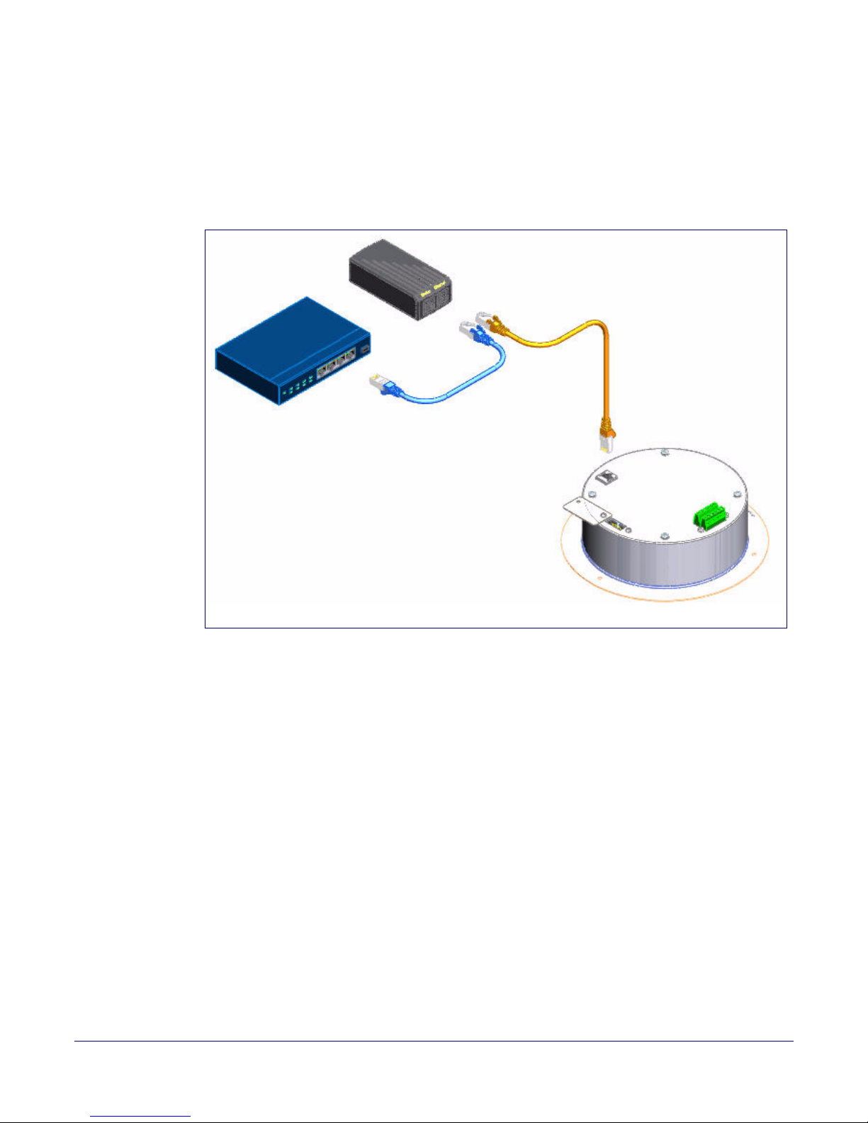
2.2.3 Singlewire-enabled Speaker (with PoE Injector) to a 802.3af Compliant PoE Switch
In Figure 2-2, if a PoE switch is not available, you will need a PoE Injector, part #010867A (ordered
separately). A PoE Injector is a power supply solution for those who have a standard Non PoE
Switch.
Figure 2-2. Singlewire-enabled Speaker Speaker (with PoE Injector) to a Non PoE Switch
23
Operations Guide 930463C CyberData Corporation
Page 31
Installing the Singlewire-enabled Speaker
GND
AC adaptor
12-14 VDC @ 3 Amps
12-14 VDC
Speaker
AUX SPEAKER (-)
AUX SPEAKER (+)
BTN SENSE GND
LINE OUT (-)
LINE OUT (+)
BUTTON LED (-)
BTN SENSE
BUTTON LED (+)
RELAY NO
RELAY COM
AUX POWER (-)
AUX POWER (+)
(+12VDC @ 1A)
J10
J9
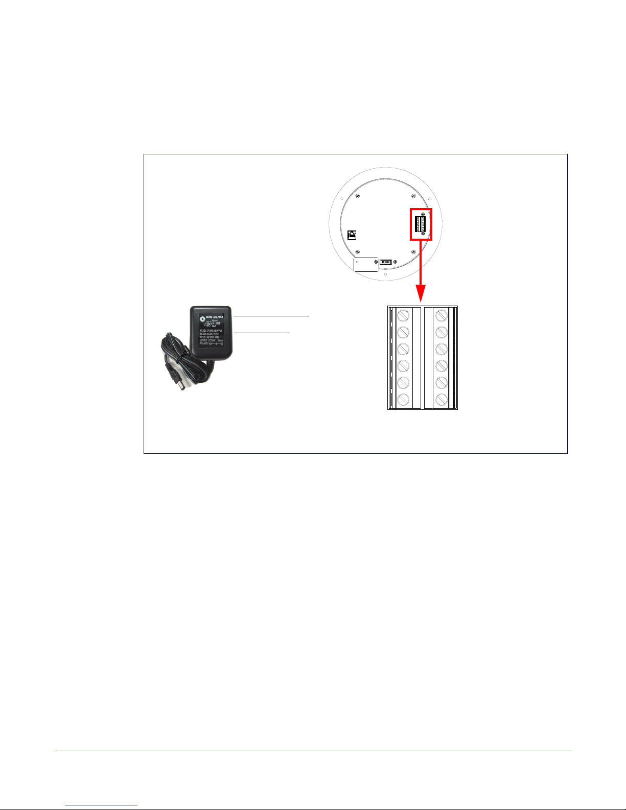
2.2.4 Running the Singlewire-enabled Speaker with Auxiliary Power
In Figure 2-3, the power for the Singlewire-enabled Speaker can either come from an 802.3af
Network connection or from an external source.
Figure 2-3. Running the V2 Speaker with Auxiliary Power
Set Up and Test the Speaker
24
Operations Guide 930463C CyberData Corporation
Page 32
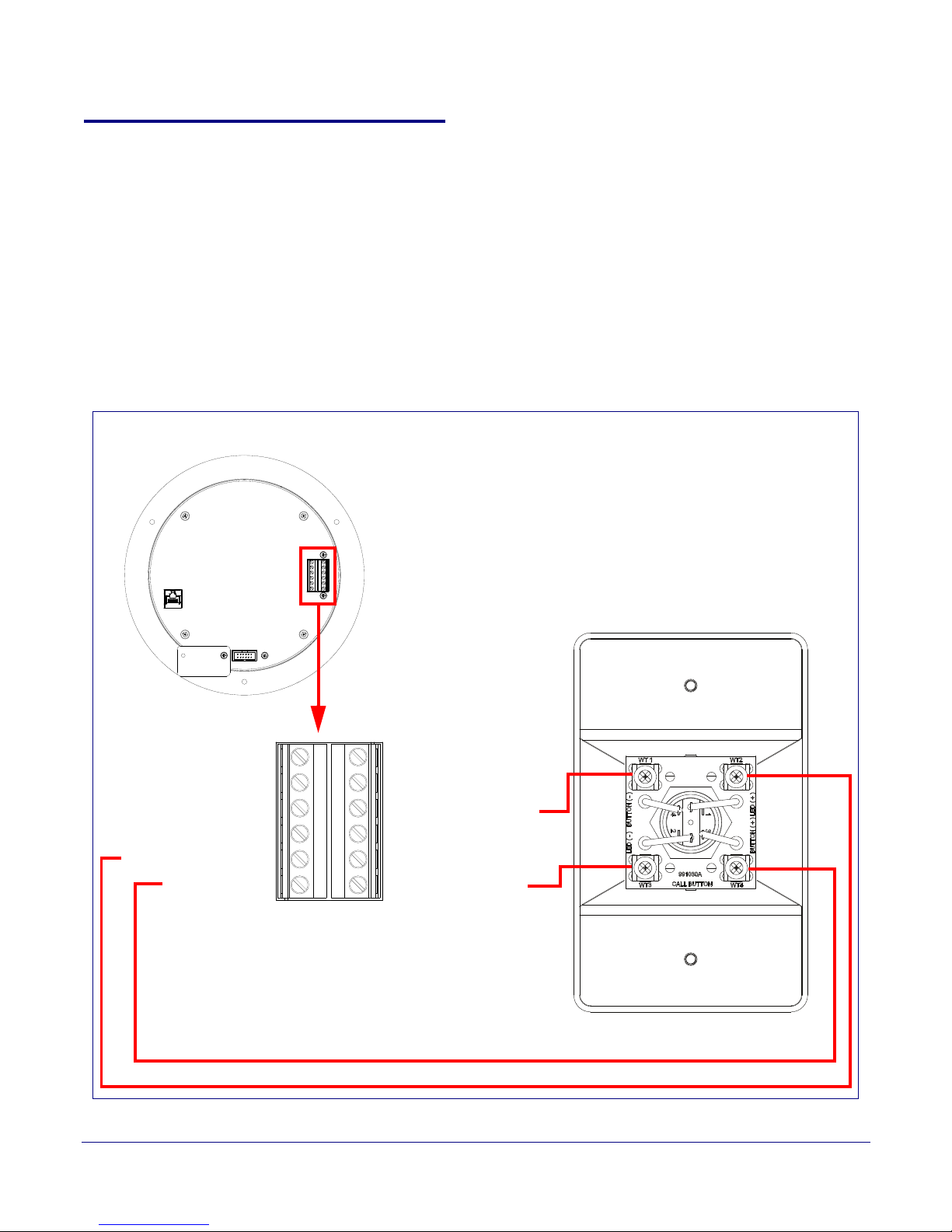
2.2.5 Installation Options
AUX SPEAKER (-)
AUX SPEAKER (+)
BTN SENSE GND
LINE OUT (-)
LINE OUT (+)
BUTTON LED (+)
RELAY NO
RELAY COM
AUX POWER (-)
AUX POWER (+)
(+12VDC @ 1A)
J10
J9
Speaker
Back View
BTN SENSE
BUTTON LED (-)
Figure 2-5 through Figure 2-6 illustrates various installation options for the Singlewire-enabled
Speaker.
2.2.6 Singlewire-enabled Speaker with Remote Call Button
In Figure 2-4, when you press the remote call button, the speaker will initiate a SIP call to a pre-
determined extension.
When you call the Speaker from a remote phone and auto-answer is not enabled, the LED on the
remote button will blink. The call will be answered when the button is pressed.
Figure 2-4. Singlewire-enabled Speaker with Remote Call Button
Installing the Singlewire-enabled Speaker
Set Up and Test the Speaker
25
Operations Guide 930463C CyberData Corporation
Page 33
Installing the Singlewire-enabled Speaker
8 Ohm Analog Speaker
16 gauge wire and
a maximum length
of 20 feet
Speaker
(Part #011120, RAL 9002)
(Part #011121, RAL 9003)
AUX SPEAKER (-)
AUX SPEAKER (+)
BTN SENSE GND
LINE OUT (-)
LINE OUT (+)
BUTTON LED (-)
BTN SENSE
BUTTON LED (+)
RELAY NO
RELAY COM
AUX POWER (-)
AUX POWER (+)
(+12VDC @ 1A)
J10
J9
Set Up and Test the Speaker
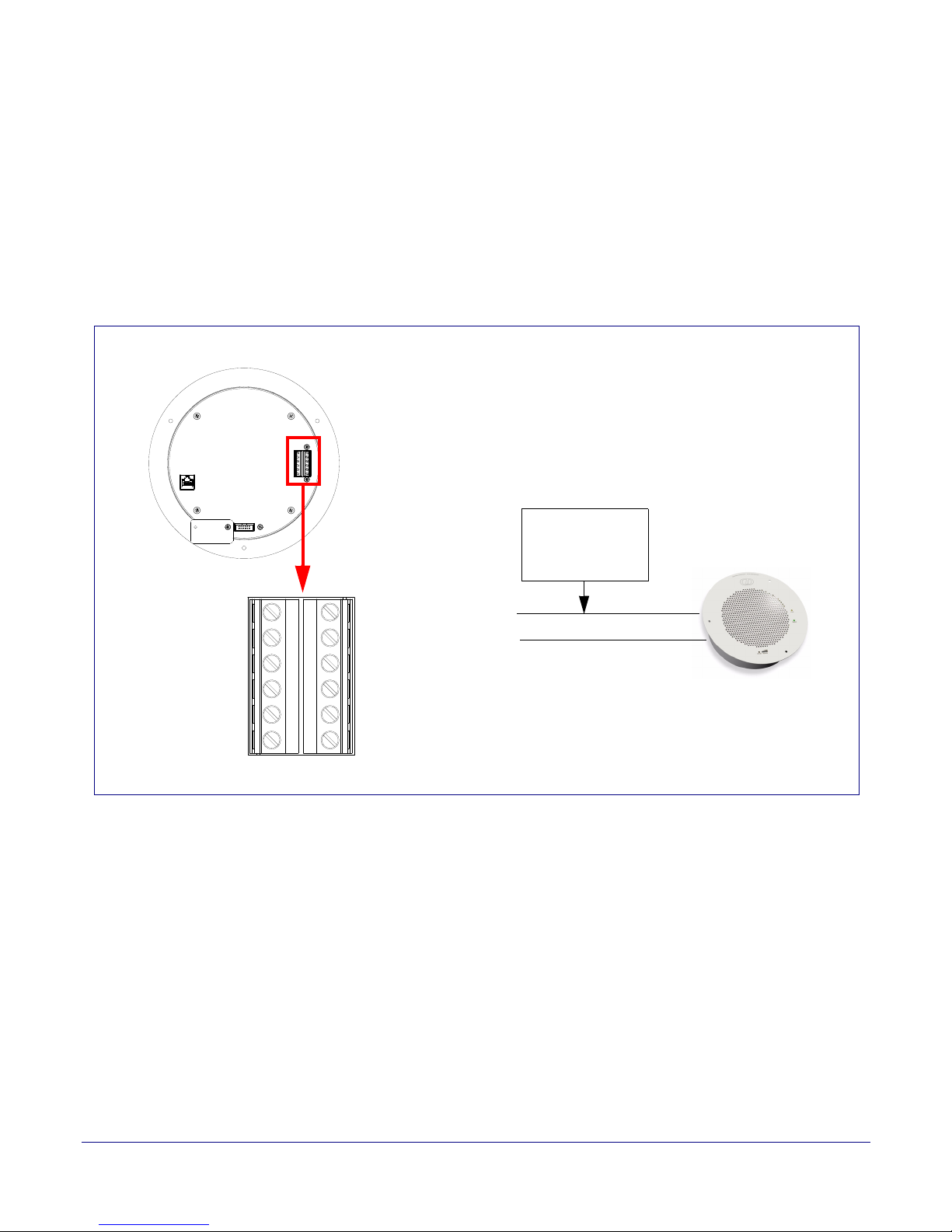
2.2.7 Singlewire-enabled Speaker with Extra Speaker Connection
In Figure 2-5, the Singlewire-enabled Speaker supports an amplified audio output for a second
analog speaker. While the total speaker wattage is the same, by connecting a low cost analog
speaker, additional coverage can be realized.
Speaker Setup When using the second speaker connection, the digital volume control needs to be set to less than
level 8 while making pages. Some adjustment of this value may be required depending on the
specific PoE switch.
Figure 2-5. Singlewire-enabled Speaker with Extra Speaker Connection
26
Operations Guide 930463C CyberData Corporation
Page 34
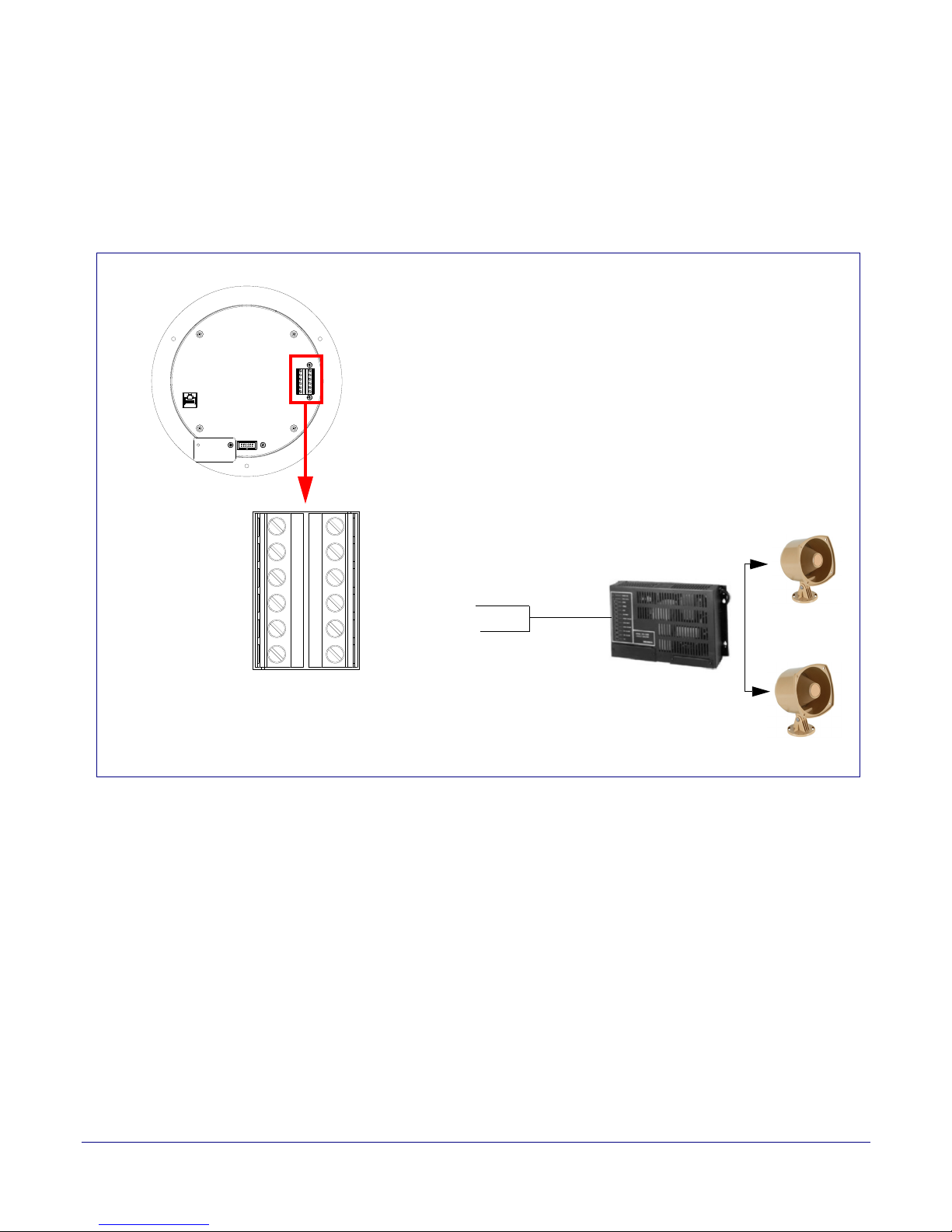
2.2.8 Singlewire-enabled Speaker with Line Out
Office area in Factory
Factory Floor
Amplifier
Line Out:
Output Signal Amplitudes 2.0 VPP maximum
Output Level +2dBm nominal
Total Harmonic Distortion 0.5% maximum
Output Impedance 10k ohm
Speaker
AUX SPEAKER (-)
AUX SPEAKER (+)
BTN SENSE GND
LINE OUT (-)
LINE OUT (+)
BUTTON LED (-)
BTN SENSE
BUTTON LED (+)
RELAY NO
RELAY COM
AUX POWER (-)
AUX POWER (+)
(+12VDC @ 1A)
J10
J9
In Figure 2-6, for areas that require more speaker volume, the Singlewire-enabled Speaker can be
connected directly to an auxiliary amplifier to drive additional horns or speakers. This is done
through the line-out connection.
Figure 2-6. Singlewire-enabled Speaker with Line Out
Installing the Singlewire-enabled Speaker
Set Up and Test the Speaker
27
Operations Guide 930463C CyberData Corporation
Page 35
Installing the Singlewire-enabled Speaker
Speaker
Status
(Green)
Network
Link/Activity
(Yellow)
Set Up and Test the Speaker
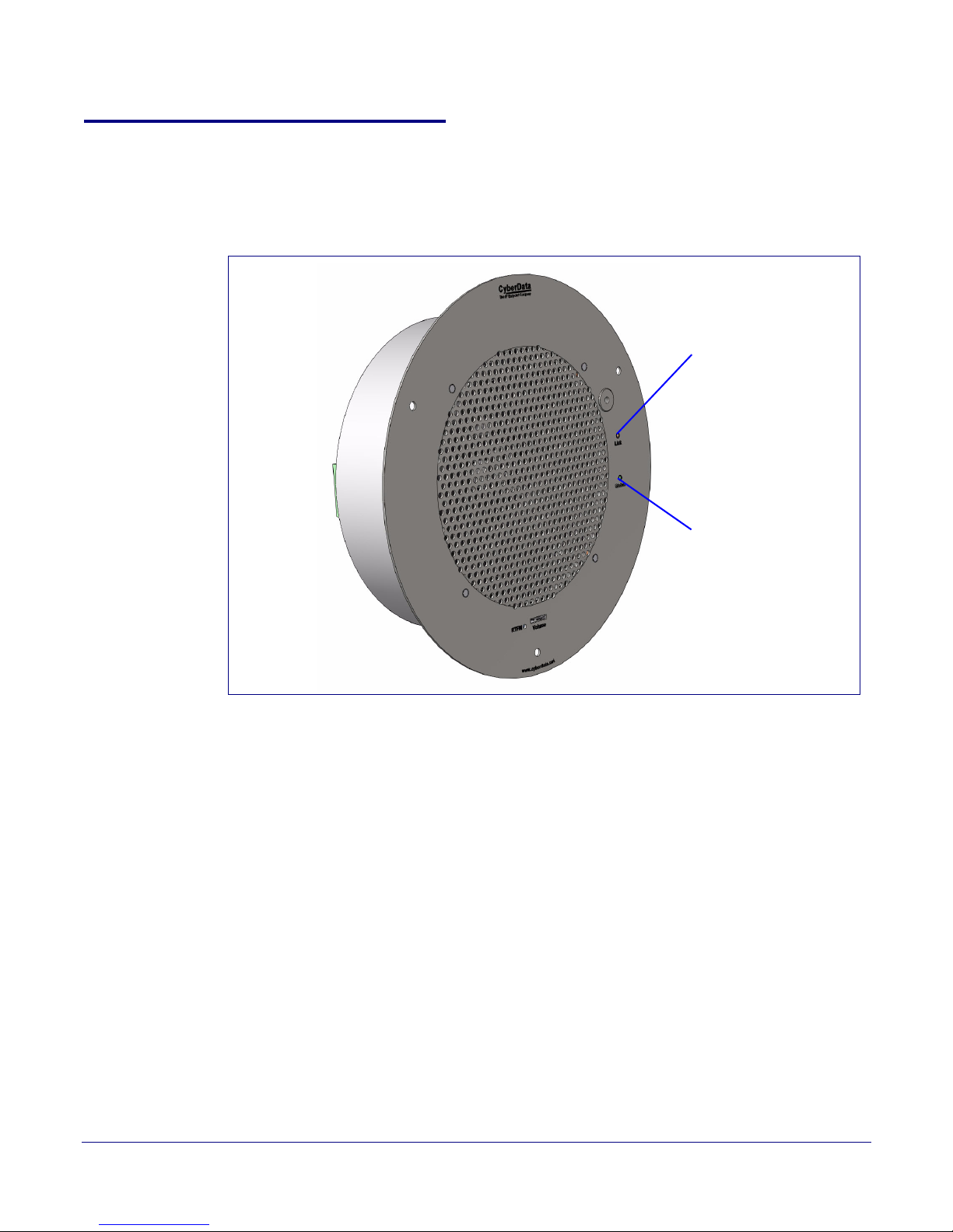
2.2.9 Confirm that the Speaker is Operational and Linked to the Network
After connecting the speaker to the 802.3af compliant Ethernet hub, the LEDs on the speaker face
confirm that the speaker is operational and linked to the network.
Figure 2-7. Status and Activity LEDs
28
2.2.10 Status LED
After supplying power to the speaker:
1. The green power/status LED and the yellow network LED comes on immediately.
Note If the board is set to use DHCP and there is not a DHCP server available on the network, it
will try five times with a three second delay between tries and eventually fall back to the
programmed static IP address (by default 10.10.10.10). This process will take approximately
80 seconds.
2.2.11 Link LED
● The Link LED is illuminated when the network link to the speaker is established.
● The Link LED blinks to indicate network traffic.
Operations Guide 930463C CyberData Corporation
Page 36
Installing the Singlewire-enabled Speaker
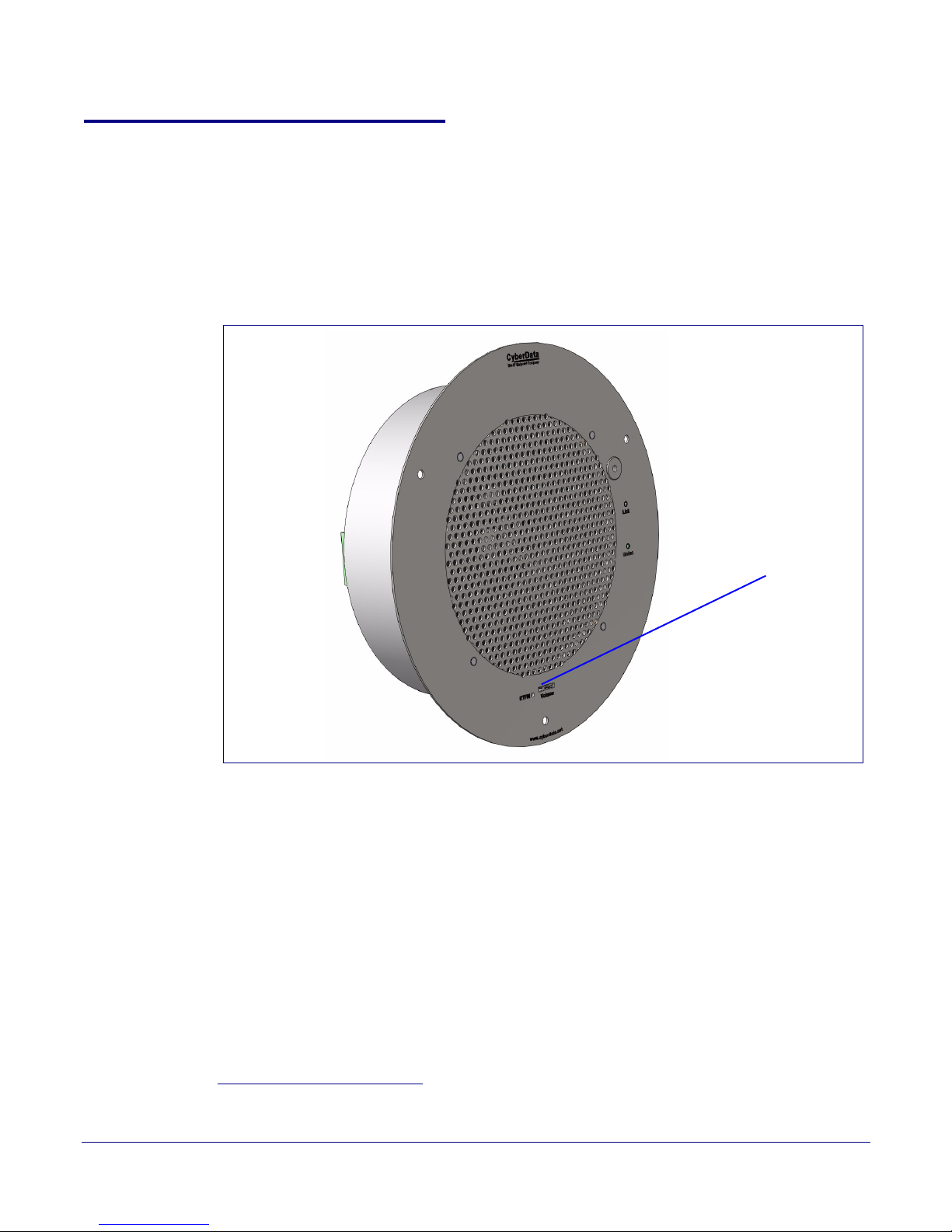
RTFM button
Set Up and Test the Speaker
2.2.12 Confirm the IP Address, Test the Audio, and Check the Volume
2.2.13 Reset Test Function Management (RTFM) Button
When the speaker is operational and linked to the network, use the Reset Test Function
Management (RTFM) button (
speaker’s IP Address, test that the audio is working, and check the volume.
Figure 2-8) on the speaker face to announce and confirm the
1
Figure 2-8. RTFM Button
29
To announce a speaker’s current IP address:
1. Press and release the RTFM button within a five second window1.
2. When you hear the IP address announcement, check the speaker volume.
Note The speaker will use DHCP to obtain the new IP address (DHCP-assigned address or
default to 10.10.10.10 if a DHCP server is not present).
Note Pressing and holding the RTFM button for longer than five seconds will restore the speaker
to the factory default settings.
1.The Restore Factory Defaults and Announce IP Address functions will only work once the
speaker has successfully retrieved its configuration file from the InformaCast Server.
Operations Guide 930463C CyberData Corporation
Page 37
2.2.14 Adjust the Volume
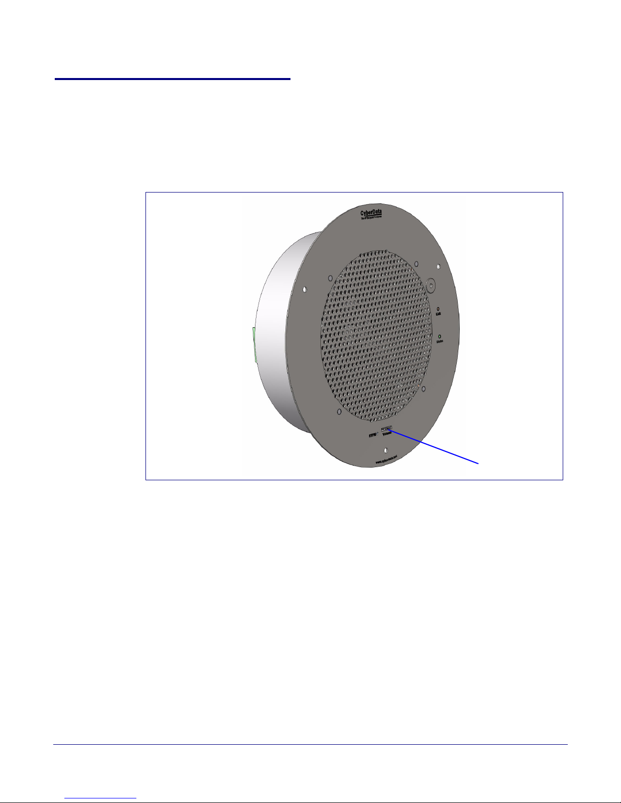
Volume control dial
To adjust the speaker volume, turn the Vo lume control dial (Figure 2-9) on the speaker face.
Note The Singlewire-enabled Speaker has two volume controls: Networked-based (as controlled
by the Singlewire protocol from InformaCast) and External (volume knob).
Installing the Singlewire-enabled Speaker
Figure 2-9. Volume Control
Set Up and Test the Speaker
30
Operations Guide 930463C CyberData Corporation
Page 38
2.2.15 Using the Microphone
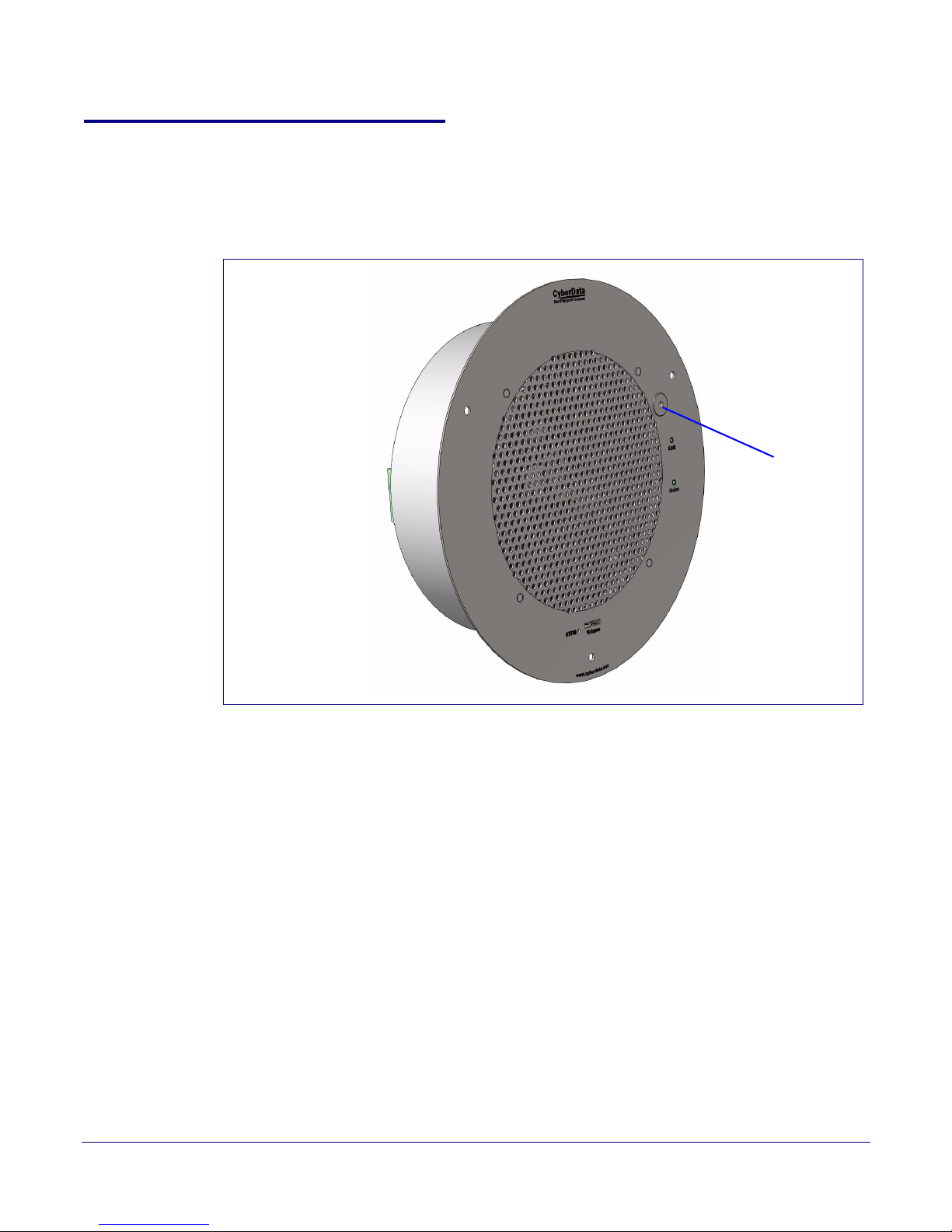
Microphone
During an active call, the microphone can be used to “talk” to someone at a pre-configured IP phone
extension. See
Figure 2-10.
Figure 2-10. Microphone
Installing the Singlewire-enabled Speaker
Set Up and Test the Speaker
31
To set the factory default settings:
1. Press and hold the RTFM button for more than five seconds.
2. The speaker announces that it is restoring the factory default settings.
Note The speaker will use DHCP to obtain the new IP address (DHCP-assigned address or
default to 10.10.10.10 if a DHCP server is not present).
Operations Guide 930463C CyberData Corporation
Page 39
2.2.16 How to Set the Factory Default Settings
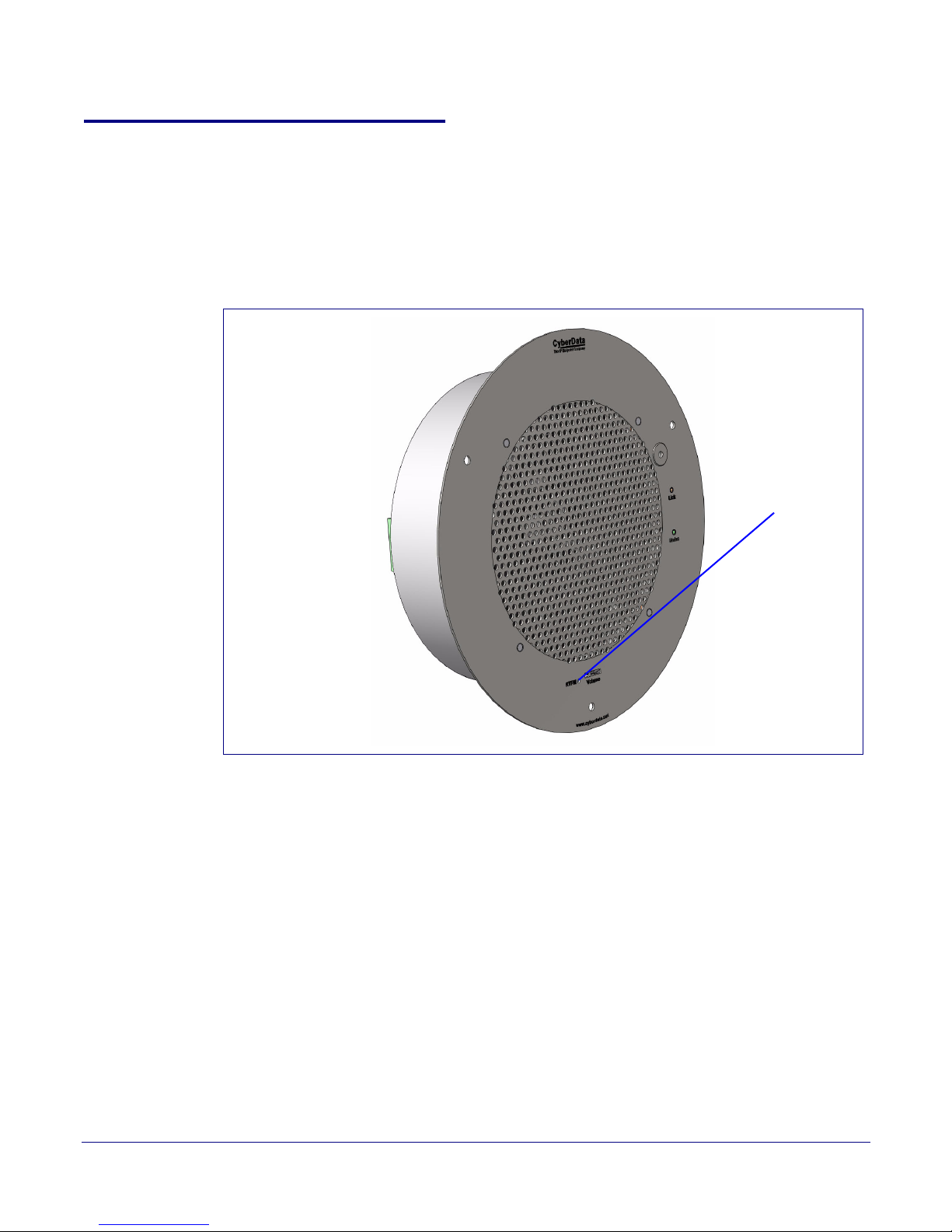
RTFM button
2.2.17 RTFM Button
When the speaker is operational and linked to the network, use the Reset Test Function
Management (RTFM) button (
Figure 2-11) on the speaker face to set the factory default settings.
Figure 2-11. RTFM Button
Installing the Singlewire-enabled Speaker
Set Up and Test the Speaker
32
To set the factory default settings:
1. Press and hold the RTFM button for more than five seconds.
2. The speaker announces that it is restoring the factory default settings.
The speaker will use DHCP to obtain the new IP address (DHCP-assigned address or default to
10.10.10.10 if a DHCP server is not present).
Operations Guide 930463C CyberData Corporation
Page 40

2.3 Configure the Speaker Parameters
To configure the speaker online, use a standard web browser.
Configuration of the speaker is taken care of by the InformaCast server. If an InformaCast server can
ot be found, the speaker will return to factory defaults as shown in Ta bl e 2-3.
n
Table 2-3. Factory Network Default Settings—Default of Network
Parameter Factory Default Setting
IP Addressing DHCP
IP Address
Web Access Username admin
Web Access Password admin
Subnet Mask
Default Gateway
a
a
a
a. Default if there is not a DHCP server present.
10.10.10.10
255.0.0.0
10.0.0.1
Installing the Singlewire-enabled Speaker
Configure the Speaker Parameters
33
Operations Guide 930463C CyberData Corporation
Page 41
Installing the Singlewire-enabled Speaker
Configure the Speaker Parameters
2.3.1 Singlewire-enabled Speaker Web Page Navigation
Ta bl e 2-4 shows the navigation buttons that you will see on every Singlewire-enabled Speaker web
page.
Table 2-4. V2 Paging Amplifier Web Page Navigation
Web Page Item Description
Link to the Home page.
34
Link to the Cloc
Link to the Update Firmware page.
k Configuration page.
a.This page is used only if the CyberData Clock Kit is installed.
a
Operations Guide 930463C CyberData Corporation
Page 42
2.3.2 Log in to the Configuration Home Page
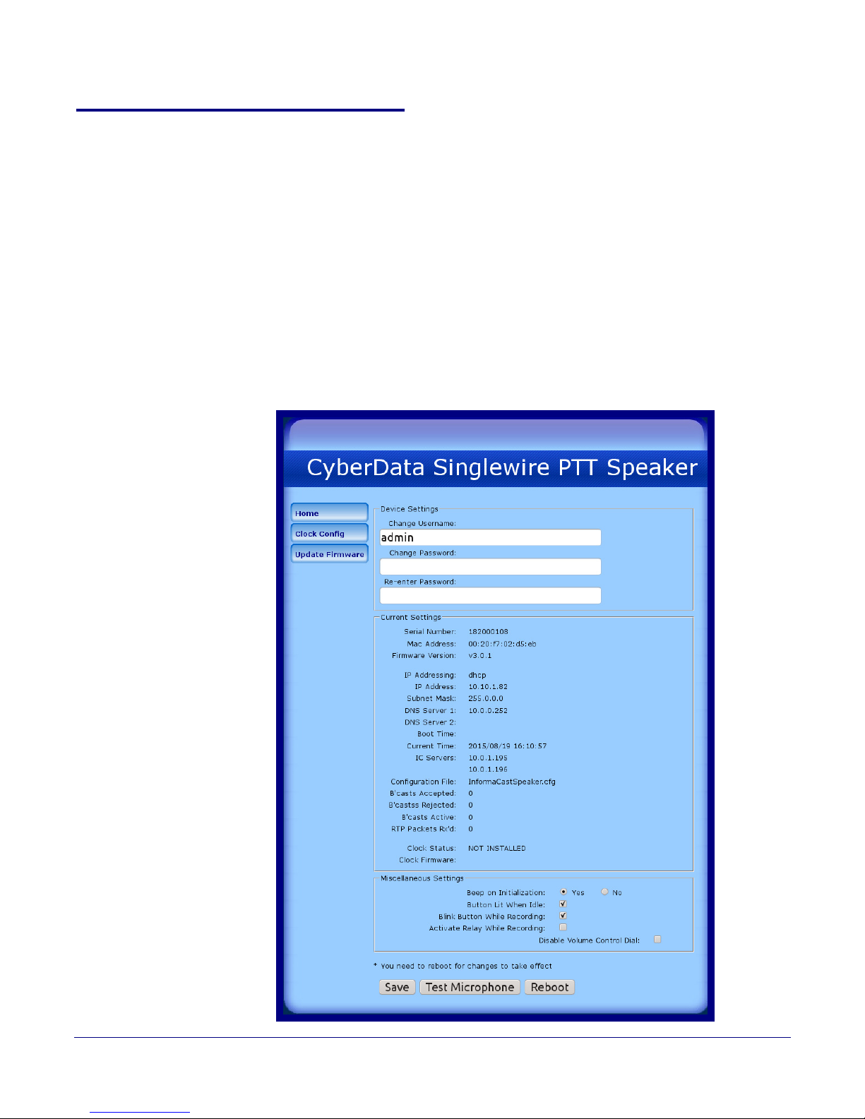
1. Open your browser to the Singlewire-enabled Speaker IP address. This can be found within the
InformaCast Server Test Menu.
Note If the network does not have access to a DHCP server, the device will default to an IP
address of 10.10.10.10.
Note Make sure that the PC is on the same IP network as the Singlewire-enabled Speaker.
2. When prompted, use the following default Web Access Username and Web Access
Password to access the Home Page (
Web Access Username: admin
Web Access Password: admin
Figure 2-12):
Figure 2-12. Home Page
Installing the Singlewire-enabled Speaker
Configure the Speaker Parameters
35
Operations Guide 930463C CyberData Corporation
Page 43

Installing the Singlewire-enabled Speaker
Configure the Speaker Parameters
3. On the Home Page, review the setup details described in Ta bl e 2-5.
Table 2-5. Home Page Overview
36
Web Page Item
Description
Device Settings
Change Username Type in this field to change the username (25 character limit).
Change Password Type in this field to change the password (19 character limit).
Re-enter Password
Type the password again in this field to confirm the new password
(19 character limit).
Current Settings
Serial Number Shows the device serial number.
Mac Address Shows the device Mac address.
Firmware Version Shows the current firmware version.
IP Addressing Shows the current IP addressing setting (D
HCP or Static).
IP Address Shows the current IP address.
Subnet Mask Shows the current subnet mask address.
DNS Server 1 Shows the current DNS Server 1 address.
DNS Server 2 Shows the current DNS Server 2 address.
Boot Time Shows the boot time.
Current Time Shows the current time.
I C Servers Shows the InformaCast Server IP addresses.
Configuration File Shows the configuration file.
B’casts Accepted Shows the number of B’casts accepted.
B’casts Rejected Shows the number of B’casts rejected.
B’casts Active Shows the number of active B’casts.
RTP Packets Rx’d Shows the number of RTP packets Rx’d.
Clock Status Shows the current clock status.
Clock Firmware Shows the current clock firmware version.
Beep on Initialization When Ye
s is selected, you will hear a beep when the device
initializes.
Button Lit When Idle When selected, the Remote Call Button LED remains lit when idle.
Blink Button While Recording When selected, the Remote Call Button LED blinks while a call is in
ress.
prog
Activate Relay While Recording When selected, the relay will activate while a call is in progress.
Click the Sa
Note: Y
Click on the Rebo
ve button to save your configuration settings.
ou need to reboot for changes to take effect.
ot button to reboot the system.
Operations Guide 930463C CyberData Corporation
Page 44
2.4 Configuring the Clock
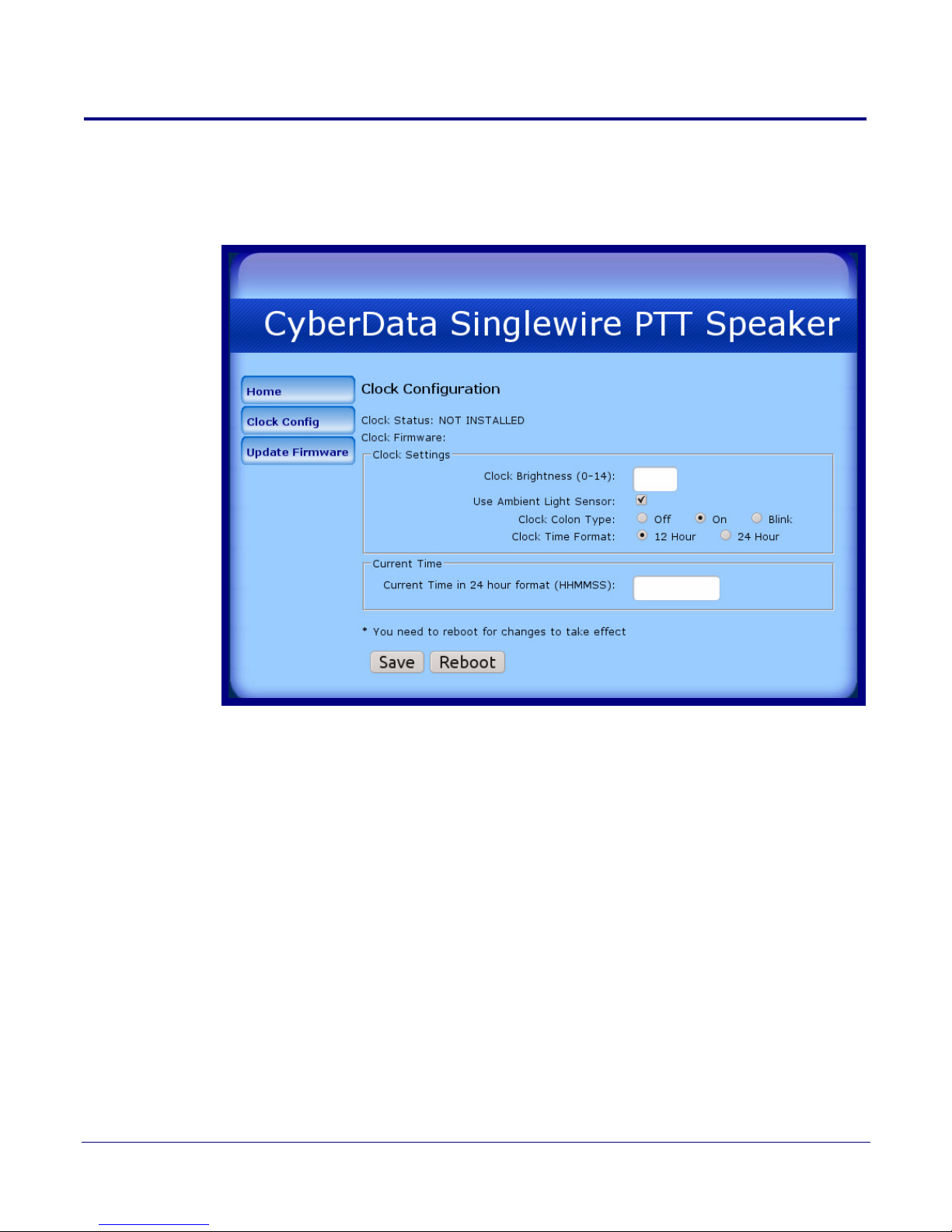
1. Click the Clock Config button to open the Clock Configuration page. See Figure 2-14.
Figure 2-13. Clock ConfigurationPage
Installing the Singlewire-enabled Speaker
Configuring the Clock
37
Note The Clock Configuration page is always visible. If a clock is not installed, the Clock Status
will indicate NOT INSTALLED. Otherwise it shows INSTALLED.
Operations Guide 930463C CyberData Corporation
Page 45
Installing the Singlewire-enabled Speaker
Configuring the Clock
Ta bl e 2-6 shows the web page items on the NTP Server and Clock Configuration page.
Table 2-6. NTP Server and Clock Configuration
Web Page Item Description
Clock Status Displays the current clock status.
38
Clock Firmware
Displays the current clock firmware version.
Clock Settings
Clock Brightness (0-14) Allows you to select the clock brightness level (0-14)
(2 character limit)
Use Ambient Light Sensor Enables or disables the ambient light sensor.
Clock Color Type Allows you to select the clock colon type (Off, On, or
Blink)
Clock Time Format Allows you to select the clock format (12 or 24 hour)
Current Time
Current Time in 24 hour format (HHMMSS) Allows you to input the current time in the 24 hour format.
(6 character limit)
Click the Sa
Note: Y
Click on the Re
ve button to save your configuration settings.
ou need to reboot for changes to take effect.
boot button to reboot the system.
Operations Guide 930463C CyberData Corporation
Page 46

Installing the Singlewire-enabled Speaker
Upgrade the Firmware and Reboot the Singlewire-enabled Speaker
2.5 Upgrade the Firmware and Reboot the Singlewireenabled Speaker
2.5.1 Upgrade the Firmware
To update the firmware from your computer:
1. Please contact VoIP Technical Support to obtain the latest Singlewire-enabled Speaker
firmware file by submitting a contact form at the following website:
http://support.cyberdata.net/
2. Log in to the Singlewire-enabled Speaker home page as instructed in Section 2.3.2, "Log in to
the Configuration Home Page".
39
Operations Guide 930463C CyberData Corporation
Page 47
Installing the Singlewire-enabled Speaker
v3.0.1
Upgrade the Firmware and Reboot the Singlewire-enabled Speaker
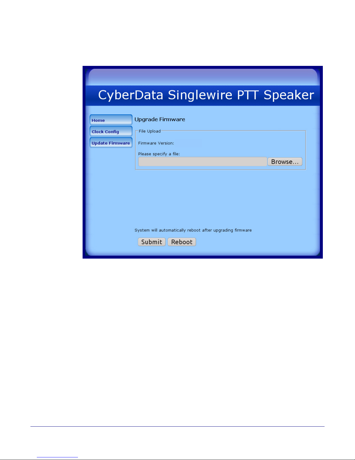
3. Click the Update Firmware button to open the Upgrade Firmware page. See Figure 2-14.
Figure 2-14. Firmware Upgrade Page
40
4. Click Browse, and then navigate to the location of the Singlewire-enabled Speaker firmware file.
5. Click Submit.
Note This starts the upload process. Once the Singlewire-enabled Speaker has uploaded the file,
the Uploading Firmware countdown page appears, indicating that the firmware is being
written to flash. The Singlewire-enabled Speaker will automatically reboot when the upload
is complete. When the countdown finishes, the Upgrade Firmware page will refresh. The
uploaded firmware filename should be displayed in the system configuration (indicating
successful upload and reboot).
Note The way that the integrity of the configuration file is validated has changed. There is no
problem with updating the firmware but if you downgrade (or downgrade, make some
changes, and then upgrade again) the device may think that the configuration is corrupt and
restore defaults.
Operations Guide 930463C CyberData Corporation
Page 48
Installing the Singlewire-enabled Speaker
Upgrade the Firmware and Reboot the Singlewire-enabled Speaker
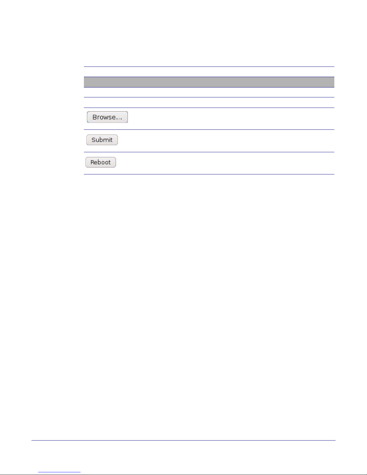
Ta bl e 2-7 shows the web page items on the Upgrade Firmware page.
Table 2-7. Firmware Upgrade Settings
41
Web Page Item
Description
File Upload
Firmware Version Shows the current firmware version.
Please specify a file Refer to the Br
Use the Br
owse button description.
owse button to navigate to the location of the
firmware file that you want to submit.
Click on the Submit b
utton to automatically submit the
selected firmware and reboot the system.
Click on the Re
boot button to reboot the system.
Operations Guide 930463C CyberData Corporation
Page 49
Upgrade the Firmware and Reboot the Singlewire-enabled Speaker
Reboot
2.5.2 Reboot the Singlewire-enabled Speaker
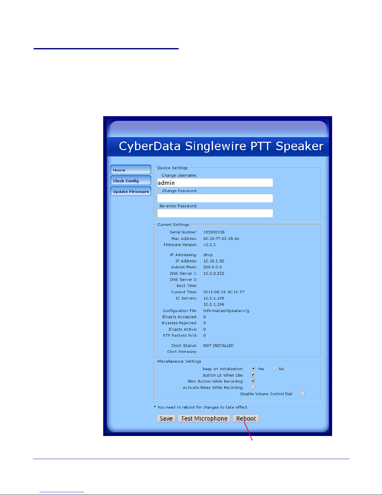
To reboot a Singlewire-enabled Speaker, log in to the web page as instructed in Section 2.3.2, "Log
in to the Configuration Home Page".
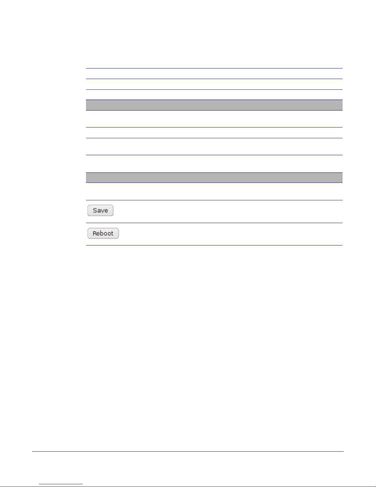
1. Click Update Firmware to open the Upgrade Firmware page (Figure 2-15).
Figure 2-15. Reboot System Section
Installing the Singlewire-enabled Speaker
42
Operations Guide 930463C CyberData Corporation
Page 50
Installing the Singlewire-enabled Speaker
Upgrade the Firmware and Reboot the Singlewire-enabled Speaker
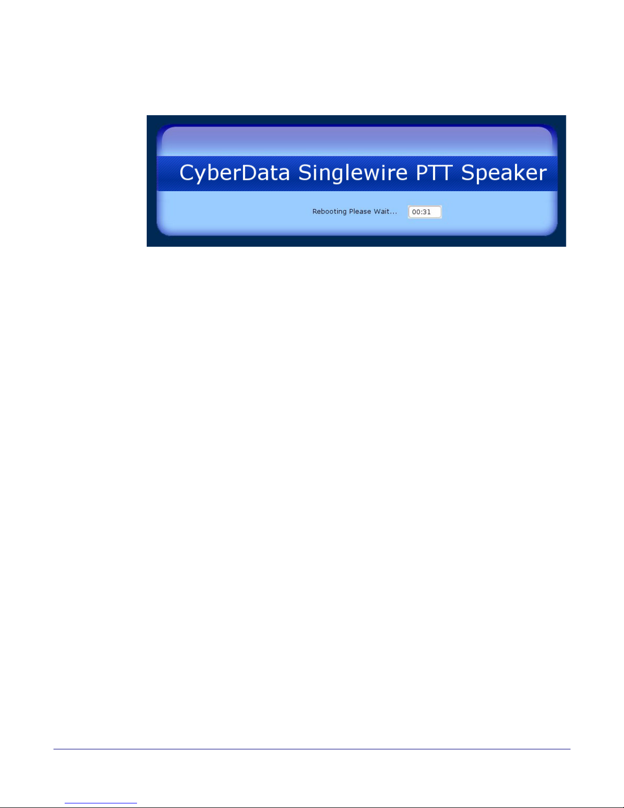
2. Click Reboot. A normal restart will occur and you will see the following Reboot page.
Figure 2-16. Reboot Page
43
Operations Guide 930463C CyberData Corporation
Page 51
Installing the Singlewire-enabled Speaker
Edit IP Speakers
Identifying and Testing a Ceiling Speaker when Using InformaCast 8.1 or Later
2.6 Identifying and Testing a Ceiling Speaker when Using
InformaCast 8.1 or Later
This section describes the basic process for identifying and testing the CyberData IP Ceiling speaker
when using Singlewire's InformaCast software version 4.0 or later.
Note If you have questions or need help, please consult your InformaCast documentation and or
contact the CyberData support team.
Note CyberData's support is limited to IP endpoint functionality when used with an InformaCast
system.
To add the Singlewire-enabled Speaker to the InformaCast server:
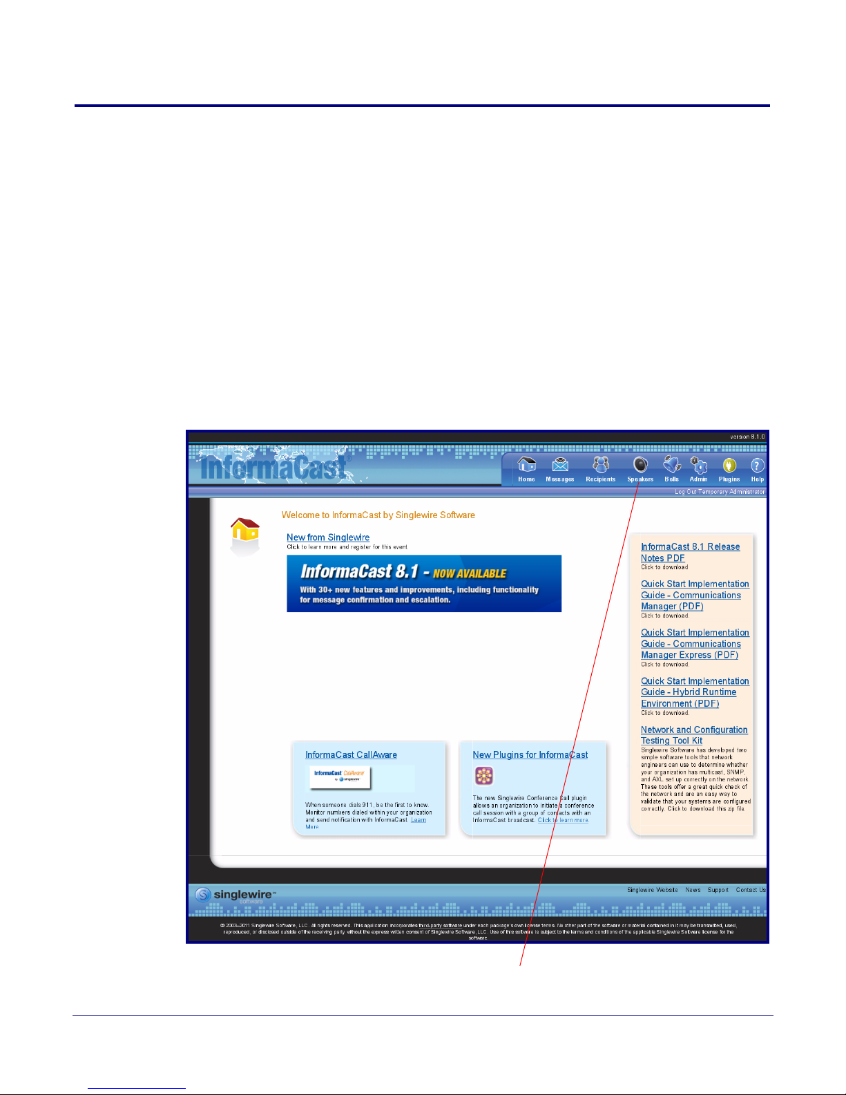
1. Click Edit IP Speakers on the Main Screen of the Singlewire Informacast Server Web
Interface.
Figure 2-17. Main Screen of the Singlewire InformaCast Server Web Interface
44
Operations Guide 930463C CyberData Corporation
Page 52
Installing the Singlewire-enabled Speaker
View
InformaCast has detected new speakers.
Identifying and Testing a Ceiling Speaker when Using InformaCast 8.1 or Later
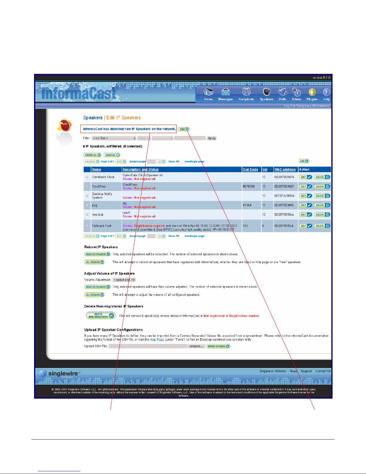
2. On the IP Speaker Configuration page, InformaCast will indicate that it has detected new
speakers. Click View.
Figure 2-18. IP Speaker Configuration Page
45
Operations Guide 930463C CyberData Corporation
Page 53
Installing the Singlewire-enabled Speaker
Te st
Identifying and Testing a Ceiling Speaker when Using InformaCast 8.1 or Later
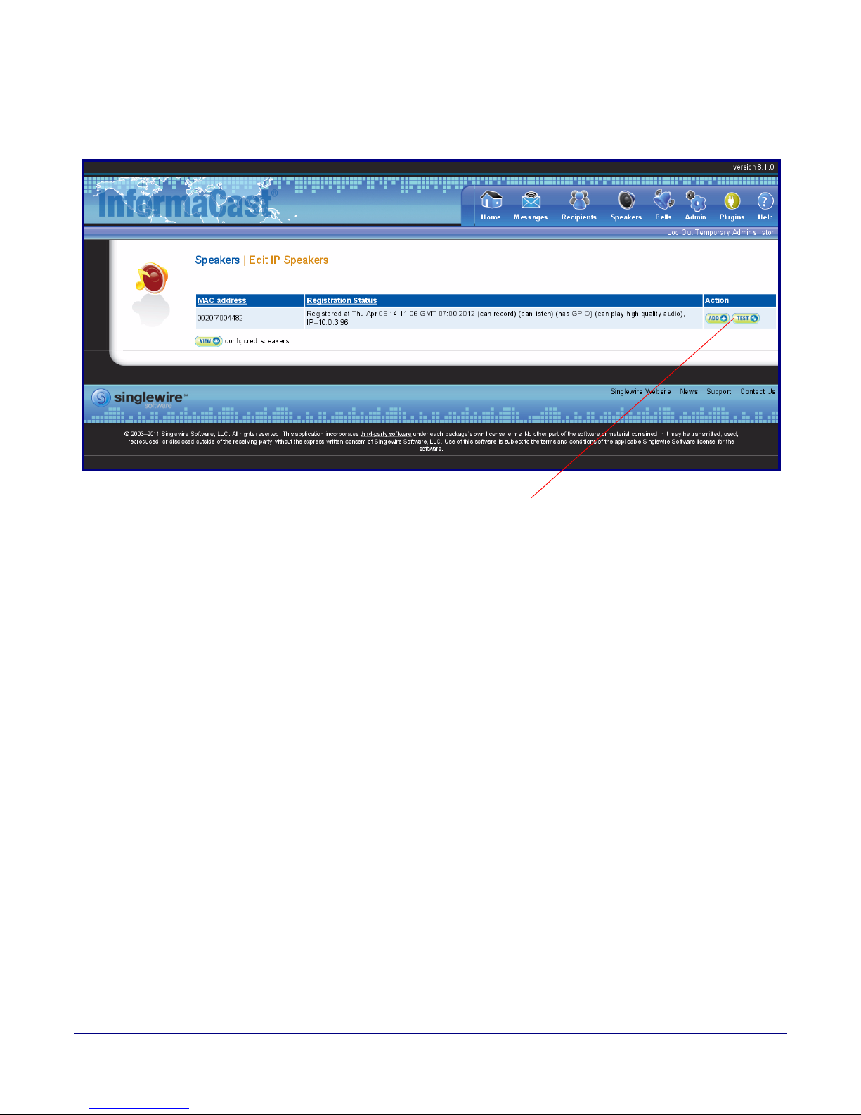
3. The IP Speaker Configuration page will show four newly detected speakers. Click Test.
Figure 2-19. IP Speaker Configuration Page
46
Operations Guide 930463C CyberData Corporation
Page 54
Installing the Singlewire-enabled Speaker
Test duration Te s tCancelView Speaker’s Status Page
Identifying and Testing a Ceiling Speaker when Using InformaCast 8.1 or Later
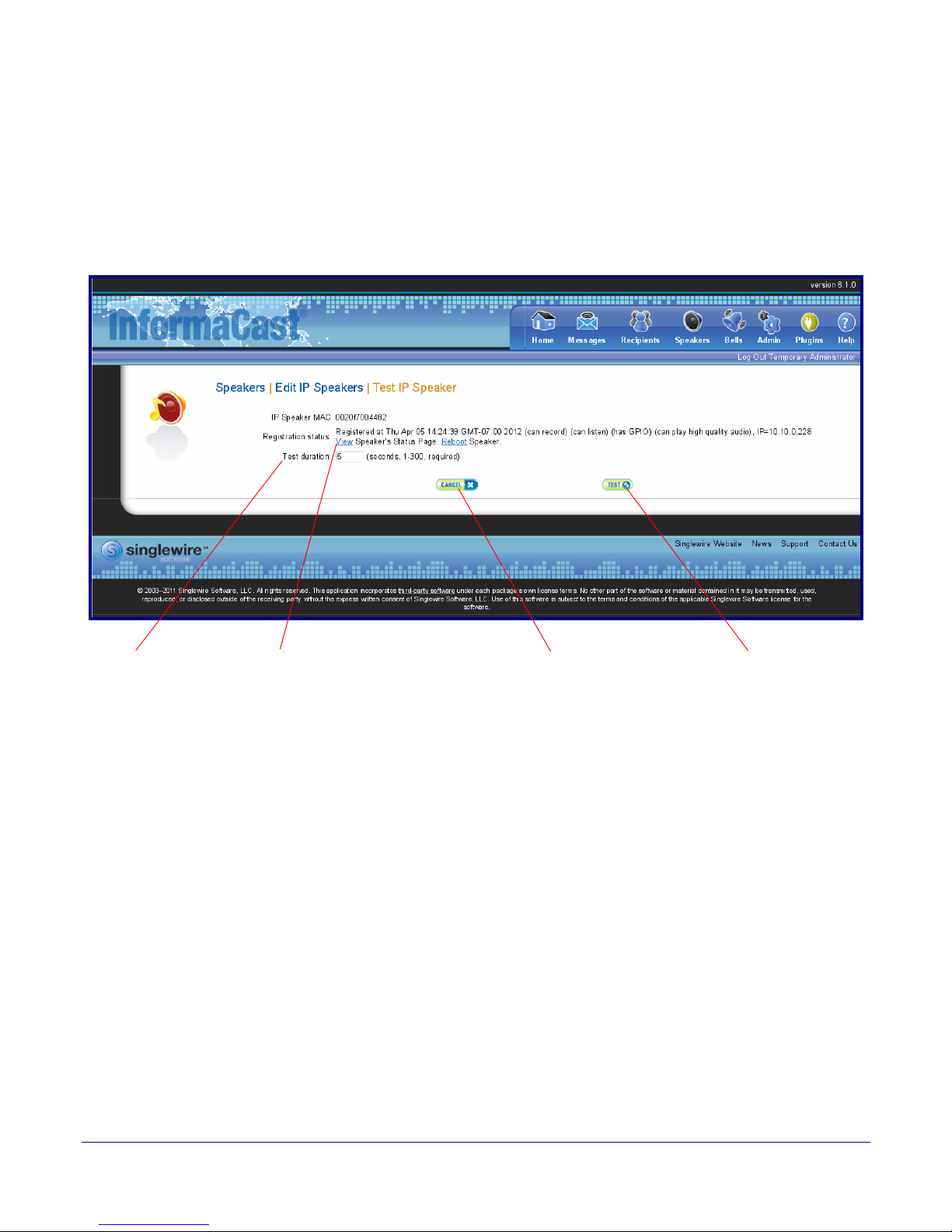
4. On the Test IP Speaker page, Enter a number into the Test duration field.
5. Click Test.
6. You will hear a tone from the speaker being testing.
7. After the test, click Cancel to return to the IP Configuration page.
Figure 2-20. Test IP Speaker Page
47
Operations Guide 930463C CyberData Corporation
Page 55
Installing the Singlewire-enabled Speaker
Add
Identifying and Testing a Ceiling Speaker when Using InformaCast 8.1 or Later
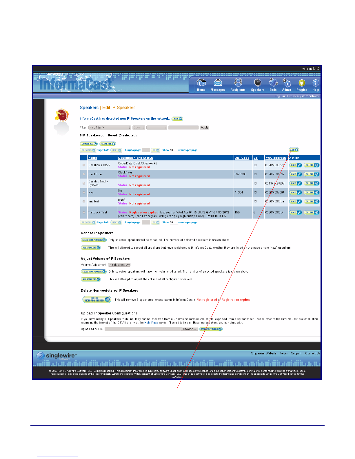
8. On the IP Speaker Configuration page, Click Add to add a speaker to the InformaCast server.
Figure 2-21. IP Configuration Page
48
Operations Guide 930463C CyberData Corporation
Page 56
Installing the Singlewire-enabled Speaker
Add
Identifying and Testing a Ceiling Speaker when Using InformaCast 8.1 or Later
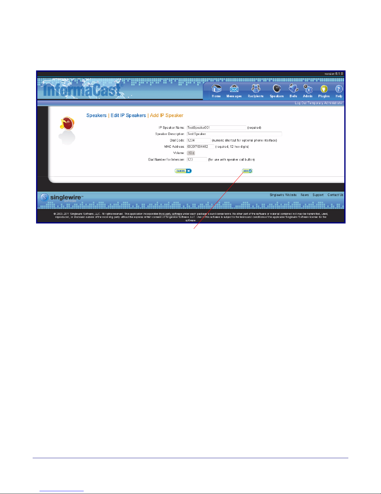
9. On the Add IP Speaker page, Fill out appropriate fields and click Add.
Figure 2-22. Add IP Speaker Page
49
Your speaker is now registered to the InformaCast server. You now can configure this device as part
of the InformaCast system setup as required.
Operations Guide 930463C CyberData Corporation
Page 57
Appendix A: Mounting the Speaker
A.1 Mount the Speaker
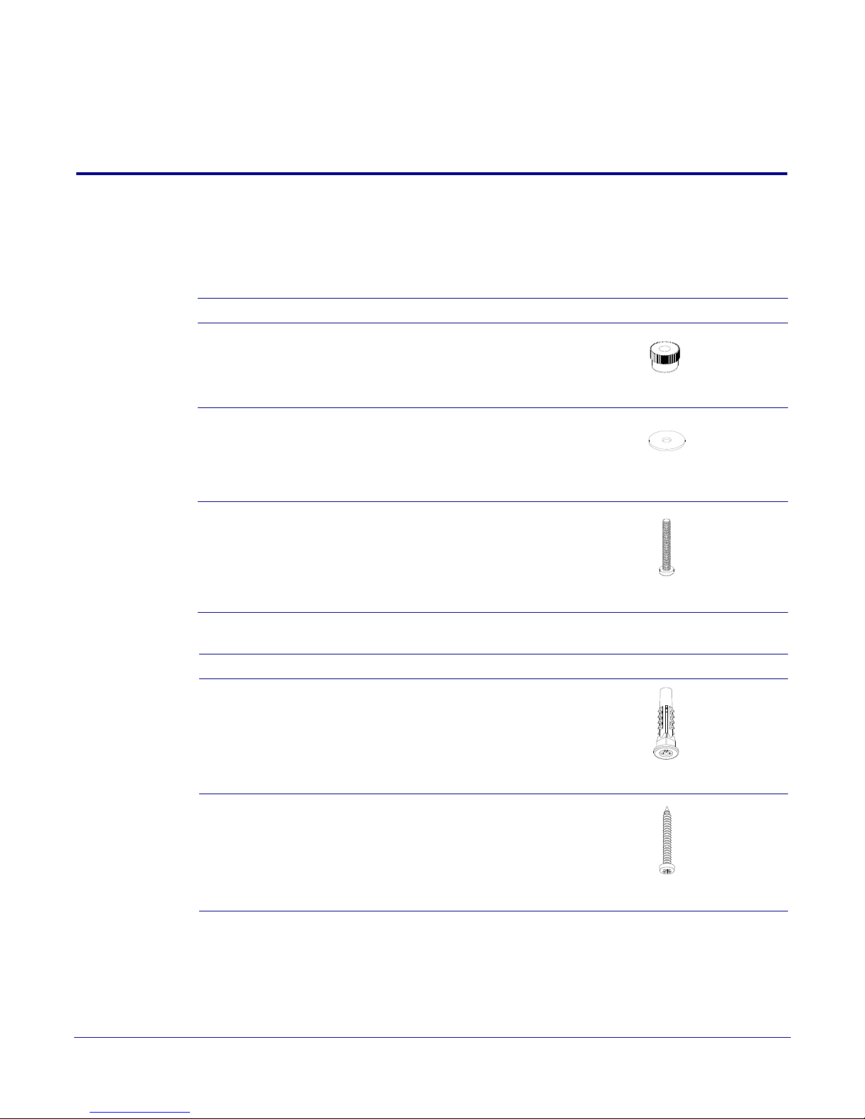
Before you mount the speaker, make sure that you have received all the parts for each speaker.
Refer to Tabl e A-1 and Ta bl e A-2.
Table A-1. Drop Ceiling Mounting Components (Part of the Accessory Kit)
Quantity Part Name Illustration
3 #8 Nylon Thumb Nuts
3 #8 Fender Washers
50
3 8-32 x 1 1/4" Mounting Screws
Table A-2. Drywall Mounting Component
Quantity Part Name Illustration
3 Plastic Ribbed Anchors
3 #8 Sheet Metal Screws
s (Part of the Accessory Kit)
Operations Guide 930463C CyberData Corporation
Page 58
*Ceiling Tile or Dry Wall
VoIP V2 Speaker
Assembly
#8 Fender Washer (3x)
#8 Nylon Thumb Nut (3x)
#6 Screw (3x)
Dry Wall Mounting Kit
Template
Plastic Ribberd Anchor (3x)
Dry Wall Mounting Kit
#8-32x1 1/4" (3X)
Ceiling Mounting Screw
*Optional Reinforcement Mount
P/N: 010991A (Sold Seperately)
Speaker Assembly
Mount the Speaker
To mount the speaker:
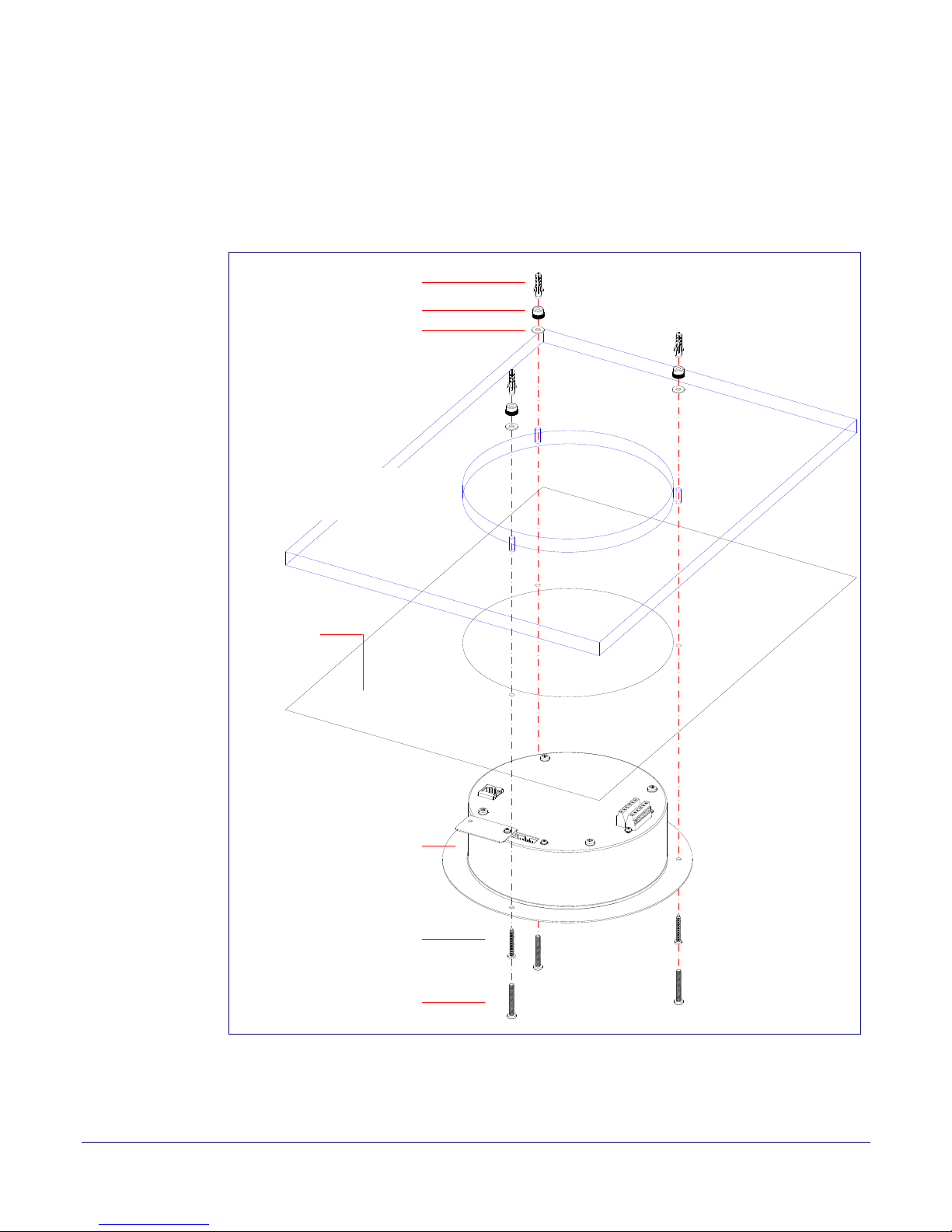
1. Use the TEMPLATE to cut the speaker hole and prepare holes for the screws (Figure A-1). This
template is located on the back page of the Installation Quick Reference Guide that is delivered
with each speaker.
Figure A-1. VoIP Speaker Assembly
51
Operations Guide 930463C CyberData Corporation
Page 59

Mount the Speaker
2. Plug the Ethernet cable into the Speaker Assembly. Section 2.2.9, "Confirm that the Speaker is
Operational and Linked to the Network" explains how the Link and Status LEDs work.
3. At this point:
•For drop ceiling mounting, position the VoIP SPEAKER ASSEMBLY in the ceiling so that its
screw holes align with those you prepared.
•For drywall mounting, place the three PLASTIC RIBBED ANCHORS in the holes you prepared,
and position the VoIP SPEAKER ASSEMBLY over them, aligning the screw holes in the
assembly with the anchors.
4. To fasten the speaker:
•For drop ceiling mounting, use the three 8-32 x 1 1/4" MOUNTING SCREWS, #8 NYLON
THUMB NUTS, and #8 FENDER WASHERS to secure the speaker.
Note For weak ceiling tile, CyberData offers a reinforcing mount (CyberData part number
010991A).
•For drywall mounting, use the three #8 SHEET METAL SCREWS to secure the speaker.
52
Operations Guide 930463C CyberData Corporation
Page 60

Appendix B: Troubleshooting/Technical
Support
Frequently Asked Questions (FAQ)
To see a list of frequently asked questions, go to the following URL:
http://www.cyberdata.net/products/voip/digitalanalog/singlewirespeakerptt/faqs.html
Documentation
The documentation for this product is released in an English language version only. You can
download PDF copies of CyberData product documentation by going to the following URL:
http://www.cyberdata.net/products/voip/digitalanalog/singlewirespeakerptt/docs.html
53
Operations Guide 930463C CyberData Corporation
Page 61

B.1 Contact Information
Contact Information
54
Contact
Sales
Technical
Support
Returned
Materials
Authorization
CyberData Corporation
3 Justin Court
Monterey, CA 93940 USA
www.CyberData.net
Phone: 800-CYBERDATA (800-292-3732)
Fax: 831-373-4193
Sales 831-373-2601 Extension 334
The fastest way to get technical support for your VoIP product is to submit a VoIP Technical
Support form at the following website:
http://support.cyberdata.net/
The Support Form initiates a ticket which CyberData uses for tracking customer requests. Most
importantly, the Support Form tells us which PBX system and software version that you are
using, the make and model of the switch, and other important information. This information is
essential for troubleshooting. Please also include as much detail as possible in the Comments
section of the Support Form.
Phone: (831) 373-2601, Ext. 333
Email: [email protected]
To return the product, contact the Returned Materials Authorization (RMA) department:
Phone: 831-373-2601, Extension 136
Email: [email protected]
When returning a product to CyberData, an approved CyberData RMA number must be printed
on the outside of the original shipping package. Also, RMA numbers require an active VoIP
Technical Support ticket number. A product will not be accepted for return without an approved
RMA number. Send the product, in its original package, to the following address:
CyberData Corporation
3 Justin Court
Monterey, CA 93940
Attention: RMA "your RMA number"
RMA Status Form
If you need to inquire about the repair status of your product(s), please use the CyberData RMA
Status form at the following web address:
http://support.cyberdata.net/
B.2 Warranty and RMA Information
The most recent warranty and RMA information is available at the following website address:
http://support.cyberdata.net/
Operations Guide 930463C CyberData Corporation
Page 62

Index
55
Symbols
#8 fender washers 50, 52
#8 nylon thumb nuts 50, 52
#8 sheet metal screws 50, 52
Numerics
8-32 x 1 1/4" mounting screws 50, 52
A
address, configuration login 35
adjusting volume 29
ambient operating temperature 4
announcing a speaker’s IP address 29, 31, 32
audio test 29
C
device configuration 21
dimensions 4, 5
downgrading (may restore factory defaults) 40
drivers 53
drop ceiling mounting of speaker 52
drywall mounting of speaker 52
E
Ethernet cable 52
F
factory default settings
how to set 31, 32
faqs 53
features 3
firmware
downgrading (may restore factory defaults) 40
firmware upgrade parameters 41
frequently asked questions (faqs) 53
clock configuration 38
clock configuration page 37
clock status 37
configurable parameters 36
configuration
device 21
using Web interface 33
configuration home page 35
confirming IP address 29
contact information 54
contact information for CyberData 54
CyberData contact information 54
CyberData support limited to IP endpoint functionality 44
D
default
gateway 21, 33
IP address 21, 33
subnet mask 21, 33
username and password 21, 33
web login username and password 35
default gateway 21, 33
default login address 35
H
home page 35
I
identifying the speaker (when using InformaCast 4.0) 44
identifying your product 2
illustration of speaker mounting process 50
InformaCast
Add IP Speaker Page 49
IP Speaker Configuration page 45
Test IP Speaker Page 47
testing and identifying a Singlewire-enabled ceiling
speaker
InformaCast needs to be 4.0 or higher 1
installation, typical speaker system 3
IP address 21, 33
IP addressing
default
IP addressing setting 21, 33
44
Operations Guide 930463C CyberData Corporation
Page 63

56
L
link LED 52
log in address 35
M
mounting a speaker 50
N
navigation (web page) 34
navigation table 34
network link activity, verifying 28
NTP server 38
O
output 4
overview 1
P
parts
#8 fender washers 50
#8 nylon thumb nuts 50
#8 sheet metal screws 50
8-32 x 1 1/4" mounting screws 50
plastic ribbed anchors 50
password
login 35
restoring the default 21, 33
pdf copies 53
plastic ribbed anchors 50, 52
port baud rate 4
power requirement 4
power, connecting to speaker 22
product
configuring 33
mounting 50
parts list 20
product features 3
product overview 1
product features 3
product specifications 4
revision history 3
product specifications 4
R
reboot 41
rebooting the Singlewire-enabled speaker 42
Reset Test Function Management (RTFM) switch 29, 32
restoring the factory default settings 31, 32
revision history 3
RMA returned materials authorization 54
RMA status 54
RTFM switch 29, 32
S
sales 54
Second Speaker Setup 26
sensitivity 4
service 54
Singlewire Informacast Server Web Interface 44
Singlewire-enabled Ceiling Speaker
how to identify 2
Singlewire-enabled Speaker
installation 1, 3
Singlewire-enabled Speaker (with PoE Injector) to a
802.3af Compliant PoE Switch
Singlewire-enabled Speaker to a 802.3af Compliant PoE
22
Switch
Singlewire-enabled Speaker with Extra Speaker
Connection
Singlewire-enabled Speaker with Line Out 27
speaker configuration page
configurable parameters 36
status LED 52
subnet mask 21, 33
26
23
T
tech support 54
technical support 53
technical support, contact information 54
template for speaker and screw holes 51
testing audio 29
testing the speaker (when using InformaCast 4.0) 44
typical system installation 3
U
username
default for web configuration access 35
restoring the default 21, 33
utilities 53
Operations Guide 930463C CyberData Corporation
Page 64

V
verifying
network link and activity 28
power on to speaker 28
VoIP speaker assembly 52
volume, adjusting 29
W
warranty policy at CyberData 54
web access password 21, 33
web access username 21, 33
web configuration log in address 35
web page
navigation 34
web page navigation 34
web-based speaker configuration 33
weight 4
57
Operations Guide 930463C CyberData Corporation
 Loading...