

Page 1
VoIP Ceiling Speaker
and Elastix Server
Setup Guide
VoIP Ceiling Speaker
and Elastix Server
Setup Guide
Page 2
PaloSanto Solutions
Cyberdata VoIP Ceiling Speaker Setup Guide
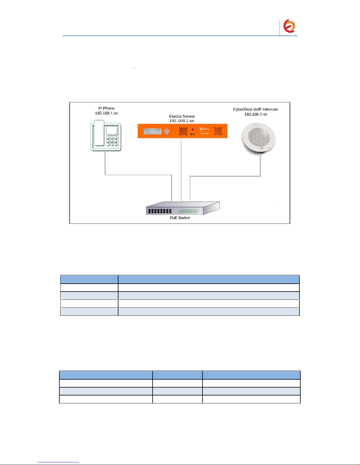
1.0 Setup Diagram
Figure 1-1 is a setup diagram for a single VoIP Ceiling Speaker configuration.
In this configuration, the VoIP Ceiling Speaker acts as a standalone SIP
telephony device.
Figure 1-1. Setup Diagram
2.0 Host PC Environment
Table 2-1. Host Server Environment Details
Description
Hardware Type
Elastix Appliance ELX-Series
Hardware Version
ELX-3000
Software Type
Elastix
Software Version
2.2
3.0 Test Setup Equipment
Table 3-1. Test Setup Equipment
Equipment
IP (SIP) Phone
CyberData VoIP Ceiling Speaker
PoE Switch
PaloSanto Solutions
Cyberdata VoIP Ceiling Speaker Setup Guide
Figure 1-1. Setup Diagram
Description
Elastix Appliance ELX-Series
ELX-3000
Elastix
2.2
Table 3-1. Test Setup Equipment
Model
Version
N/A
N/A
011098B
6.3.0
N/A
N/A
Page 3
PaloSanto Solutions
Cyberdata VoIP Ceiling Speaker Setup Guide
4.0 Setup Procedure
To set up the Elastix Server for the CyberData VoIP Ceiling Speaker,
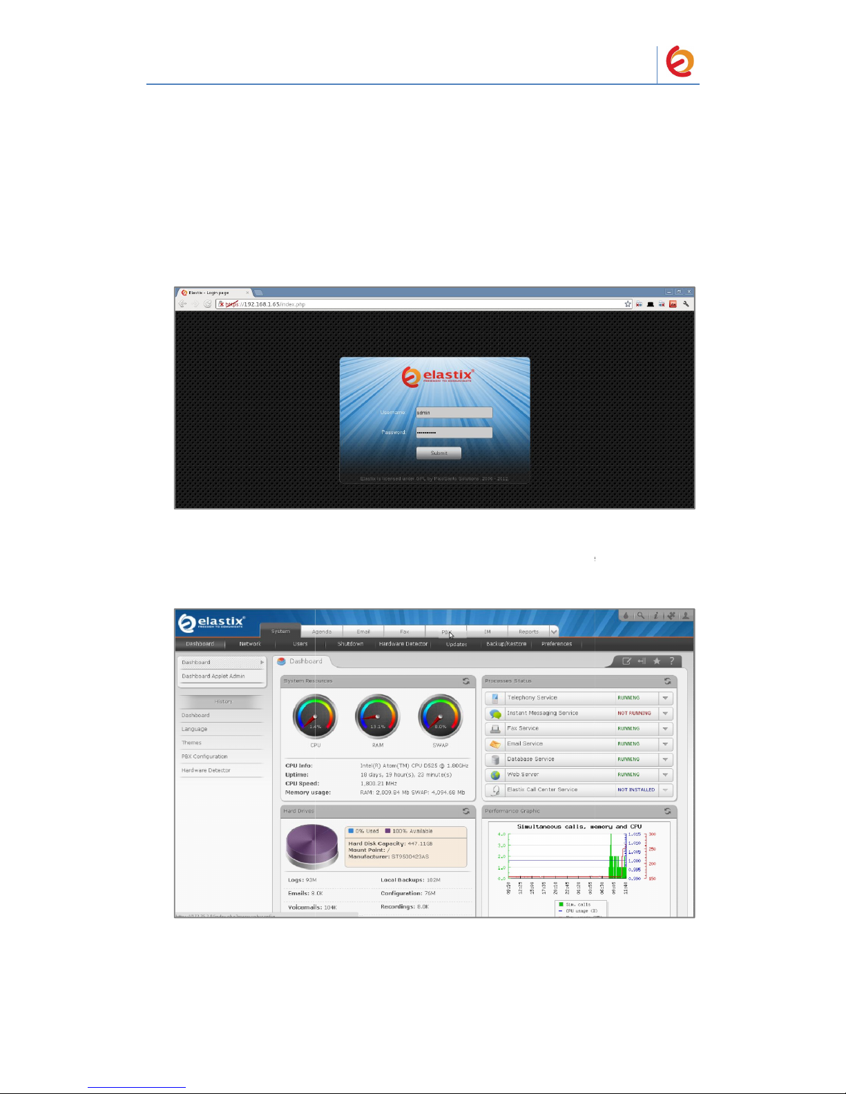
1. Go to the web address of the Elastix Server Login page. The web address is
determined by the customer, for this guide we have used the IP address 192.168.1.65
2. On the Login page, type the username and password for an administrative user into
the Username and Password fields, see Figure 4-1. The username and password are
determined by the customer.
Figure 4-1. Login
3. Press Enter or click on the Submit button to go to Elastix’s Dashboard
4. Once inside, click on the PBX tab on the menu at the top of the screen
Figure 4-2. Dashboard
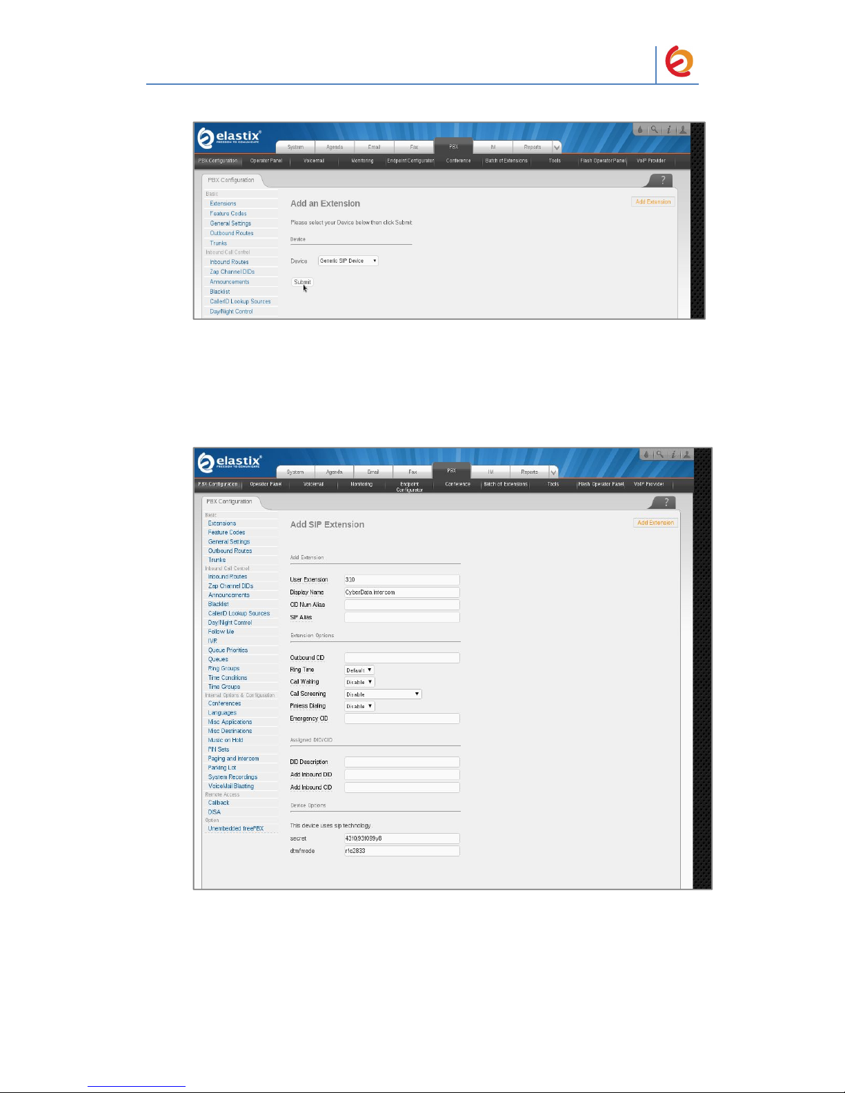
5. Click on the Submit button to add an extension, see Figure 4-3. This will take you to
the Add SIP Extension page.
PaloSanto Solutions
Cyberdata VoIP Ceiling Speaker Setup Guide
Figure 4-1. Login
Figure 4-2. Dashboard
Page 4
PaloSanto Solutions
Cyberdata VoIP Ceiling Speaker Setup Guide
Figure 4-3. Add an Extension
6. On the Add SIP Extension page (Figure 4-4), fill in the following information:
• User Extension (310 in this example)
• Display Name (‘CyberData Ceiling Speaker’ in this example)
• secret (‘43f0j93f099y8’ in this example)
Figure 4-4. Add SIP Extension
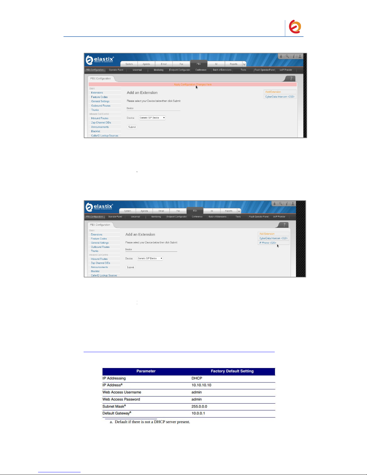
7. Click on the ‘Submit’ button at the end of the page. The extension will be created and
you will see the page on Figure 4-5 displaying the “Apply Configuration Changes Here”
pink ribbon on top of the screen.
8. Click in the “Apply Configuration Changes Here” link
Page 5
PaloSanto Solutions
Cyberdata VoIP Ceiling Speaker Setup Guide
Figure 4-5. Apply Configuration Changes Here
9. With this you have just finished creating a SIP extension that will be used by the
VoIP Ceiling Speaker to register with the Elastix Server. Repeat Steps 5 through 8 to
similarly create another extension (different values on Step 6) to be used by the IP (SIP)
Phone to register as well (extension 320 in this example). Once finished you will see
something similar to Figure 4-6
Figure 4-6. VoIP Ceiling Speaker and IP Phone extensions successfully created
10. To register the Ceiling Speaker, you will need to enter the information from the
extension created on the Elastix Server into the Ceiling Speaker by logging into the
CyberData VoIP Ceiling Speaker WebUI.
Log in to the CyberData VoIP Ceiling Speaker WebUI (Figure 4-7) by pointing your
browser to the Ceiling Speaker’s IP address.
For the initial configuration of the Ceiling Speaker, refer to the VoIP Ceiling Speaker
Operation Guide PDF which can be found at the VoIP Ceiling Speaker product page at:
http://www.cyberdata.net/products/voip/digitalanalog/ceilingspkr2/docs.html
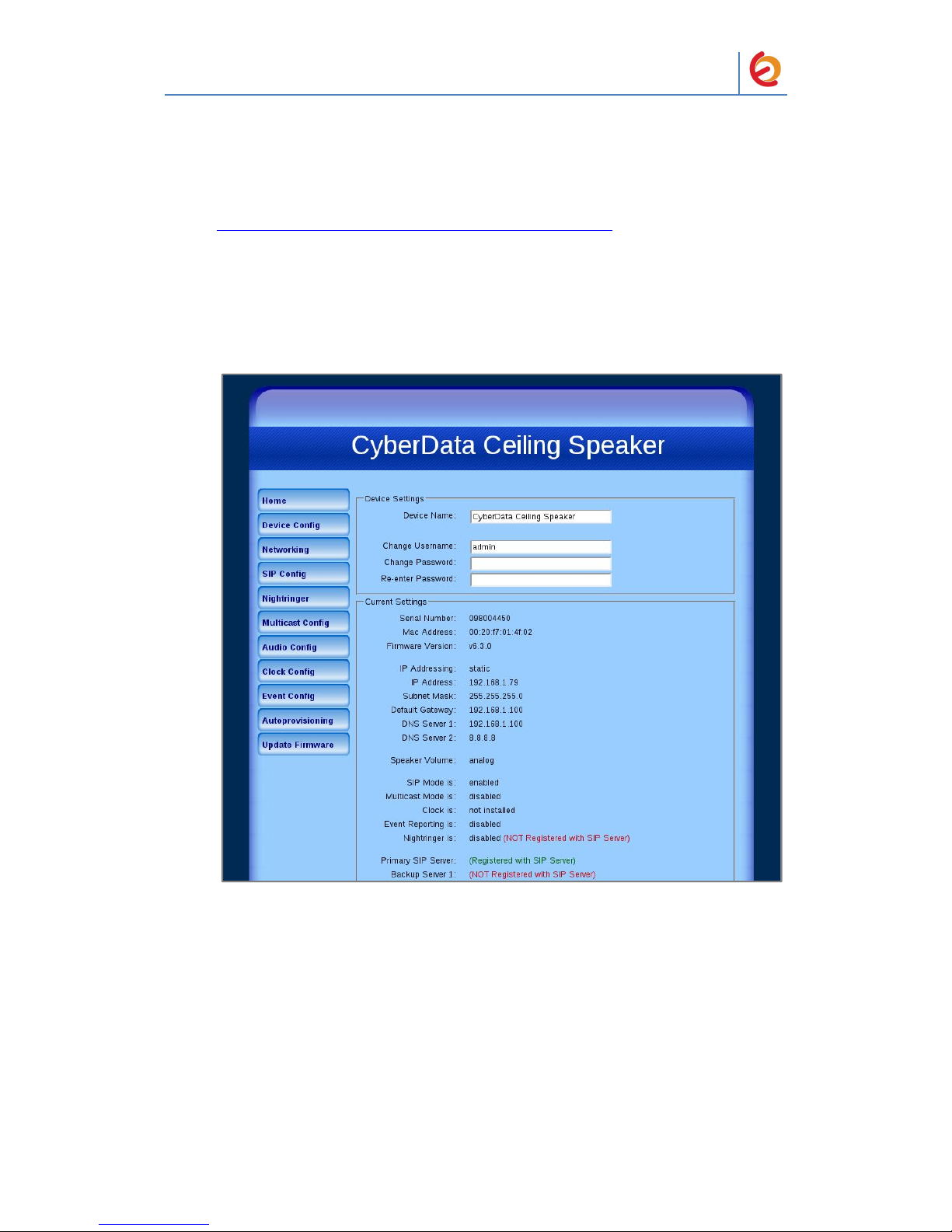
Table 4-1. Factory Default Settings
PaloSanto Solutions
Cyberdata VoIP Ceiling Speaker Setup Guide
Table 4-1. Factory Default Settings
Page 6
PaloSanto Solutions
Cyberdata VoIP Ceiling Speaker Setup Guide
Note You may also download CyberData’s VoIP Discovery Utility program which
allows you to easily find and configure the default web address of the CyberData VoIP
products.
CyberData’s VoIP Discovery Utility program is available at the following web address:
http://www.cyberdata.net/support/voip/discovery_utility.html
11. When prompted, enter the following Web Access Username and Web Access
Password to access the CyberData VoIP Ceiling Speaker WebUI (Figure 4-7)
Figure 4-7. CyberData VoIP Ceiling Speaker WebUI
Page 7
PaloSanto Solutions
Cyberdata VoIP Ceiling Speaker Setup Guide
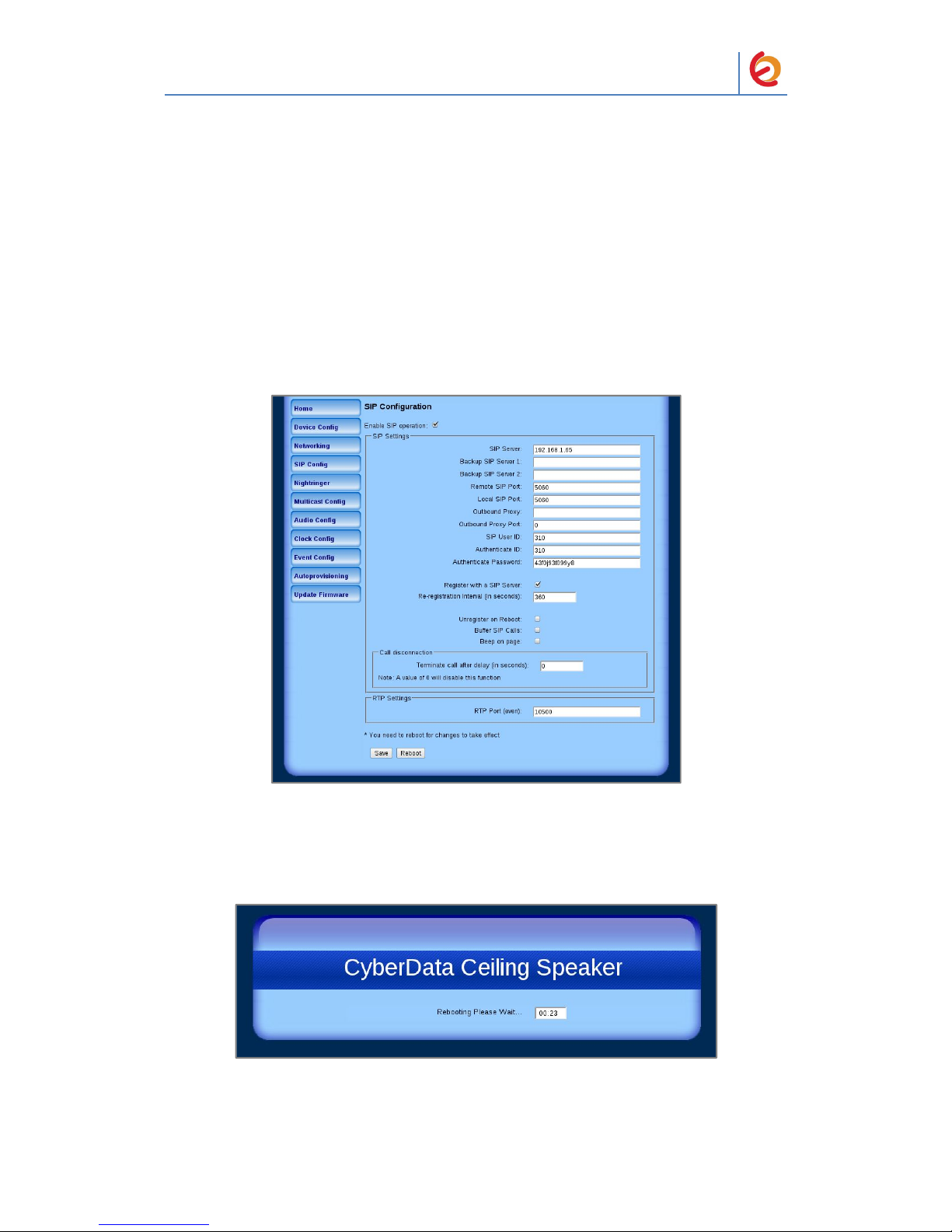
12. Use the information from the Add SIP Extension page (Figure 4-4) to enter the
following information on the SIP Config page of the VoIP Ceiling Speaker:
• SIP Server (192.168.1.65 in this example)
• SIP User ID (310 in this example)
• Authenticate ID (310 in this example)
• Authenticate Password (43f0j93f099y8 in this example)
• Dial out Extension (320 in this example)
Note Figure 4-8 is an example of a CyberData VoIP Ceiling Speaker that is configured
to extension 310
Figure 4-8. SIP Config Page
13. Click on the Save button at the bottom of the screen and then on the Reboot button
next to it. The screen on Figure 4-9 will be shown
Figure 4-9. Ceiling Speaker Reboot Timer
Page 8

PaloSanto Solutions
Cyberdata VoIP Ceiling Speaker Setup Guide
14. After the Ceiling Speaker finishes rebooting, the green Status LED on the Ceiling
Speaker will remain lit to indicate normal operation.
15. To test the Ceiling Speaker’s call reception feature, pick up the previously
configured IP (SIP) Phone and call the Ceiling Speaker’s extension number (310 in this
example). When the call is established, speak into the phone and verify that you can
hear your voice through the Ceiling Speaker.
This step completes the procedure.
 Loading...