

CyberData 011098A, 021037C, 11098, 11099 Operation Manual
VoIP V2 Speaker
Operations Guide
Part #011098*, RAL 9002, Gray White, Standard
Part #011099, RAL 9003, Signal White, Optional
*Replaces #011021
Document Part #930274I
for Firmware Version 6.0.1
CyberData Corporation
3 Justin Court
Monterey, CA 93940
(831) 373-2601

VoIP V2 Speaker Operations Guide 930274I
Phone: (831) 373-2601
Technical Support Ext. 333
support@cyberdata.net
Fax: (831) 373-4193
Company and product information at www.cyberdata.net
Part # 011098*
Part # 011099
*Replaces 011021
COPYRIGHT NOTICE:
© 2011, CyberData Corporation, ALL RIGHTS RESERVED.
This manual and related materials are the copyrighted property of CyberData Corporation. No part
of this manual or related materials may be reproduced or transmitted, in any form or by any means
(except for internal use by licensed customers), without prior express written permission of
CyberData Corporation. This manual, and the products, software, firmware, and/or hardware
described in this manual are the property of CyberData Corporation, provided under the terms of an
agreement between CyberData Corporation and recipient of this manual, and their use is subject to
that agreement and its terms.
DISCLAIMER: Except as expressly and specifically stated in a written agreement executed by
CyberData Corporation, CyberData Corporation makes no representation or warranty, express or
implied, including any warranty or merchantability or fitness for any purpose, with respect to this
manual or the products, software, firmware, and/or hardware described herein, and CyberData
Corporation assumes no liability for damages or claims resulting from any use of this manual or
such products, software, firmware, and/or hardware. CyberData Corporation reserves the right to
make changes, without notice, to this manual and to any such product, software, firmware, and/or
hardware.
OPEN SOURCE STATEMENT: Certain software components included in CyberData products are
subject to the GNU General Public License (GPL) and Lesser GNU General Public License (LGPL)
“open source” or “free software” licenses. Some of this Open Source Software may be owned by
third parties. Open Source Software is not subject to the terms and conditions of the CyberData
COPYRIGHT NOTICE or software licenses. Your right to copy, modify, and distribute any Open
Source Software is determined by the terms of the GPL, LGPL, or third party, according to who
licenses that software.
Software or firmware developed by CyberData that is unrelated to Open Source Software is
copyrighted by CyberData, subject to the terms of CyberData licenses, and may not be copied,
modified, reverse-engineered, or otherwise altered without explicit written permission from
CyberData Corporation.
TRADEMARK NOTICE: CyberData Corporation and the CyberData Corporation logos are
trademarks of CyberData Corporation. Other product names, trademarks, and service marks may be
the trademarks or registered trademarks of their respective owners.
CyberData Corporation 930274I Operations Guide

Revision Information
Revision 930274I was updated on 2/3/2011 and has the following changes:
•Updates Figure 2-3, "Running the V2 Speaker with Auxiliary Power".
•Updates Figure 2-4, "V2 Speaker with Alert Strobe".
•Updates Figure 2-5, "V2 Speaker with Auxiliary Speaker Connection".
•Updates Figure 2-7, "V2 Speaker with Line Out".
•Updates Figure 2-12, "Home Page".
•Updates Figure 2-13, "Device Configuration Page".
•Updates Figure 2-14, "Network Configuration Page".
•Updates Figure 2-15, "SIP Configuration Page".
•Updates Figure 2-16, "Nightringer Configuration Setup".
•Updates Figure 2-17, "Multicast Configuration Setup".
•Updates Figure 2-18, "Audio Configuration Page".
•Updates Figure 2-19, "Audio Configuration Page (continued)".
•Updates Figure 2-20, "Audio Configuration Page (continued)".
•Updates Figure 2-26, "Event Configuration Page".
•Updates Figure 2-27, "Autoprovisioning Configuration Page".
•Updates Figure 2-28, "Firmware Upgrade Page".
•Updates Figure 2-29, "Reboot System Section".
• Updates the “Time Zone Identifier” section.
• Updates the text of the following note for Section 2.2.3.1, "Status LED":
“If the board is set to use DHCP and there is not a DHCP server available on the network, it will
try 12 times with a three second delay between tries and eventually fall back to the programmed
static IP address (by default 10.10.10.10). This process will take approximately 80 seconds.”
• Updates the text of the following note for Section 2.2.4.1, "Reset Test Function Management
(RTFM) Switch":
“Using the RTFM switch will lock the digital volume level to 4 and disable the analog volume
control dial.”
Operations Guide 930274I CyberData Corporation
Important Safety Instructions
GENERAL ALERT
GENERAL ALERT
1. Read these instructions.
2. Keep these instructions.
3. Heed all warnings.
4. Follow all instructions.
5. Do not use this apparatus near water.
6. Clean only with dry cloth.
7. Do not block any ventilation openings. Install in accordance with the manufacturer’s
instructions.
8. Do not install near any heat sources such as radiators, heat registers, stoves, or other apparatus
(including amplifiers) that produce heat.
9. Do not defeat the safety purpose of the polarized or grounding-type plug. A polarized plug has
two blades with one wider than the other. A grounding type plug has two blades and a third
grounding prong. The wide blade or the third prong are provided for your safety. If the
provided plug does not fit into your outlet, consult an electrician for replacement of the obsolete
outlet.
10. Protect the power cord from being walked on or pinched particularly at plugs, convenience
receptacles, and the point where they exit from the apparatus.
11. Only use attachments/accessories specified by the manufacturer.
12. Refer all servicing to qualified service personnel. Servicing is required when the apparatus has
been damaged in any way, such as power-supply cord or plug is damaged, liquid has been
spilled or objects have fallen into the apparatus, the apparatus has been exposed to rain or
moisture, does not operate normally, or has been dropped.
13. Prior to installation, consult local building and electrical code requirements.
Warning
Electrical Hazard: This product should be installed by a licensed electrician
according to all local electric al and building codes .
Warning
Electrical Hazard: To prevent injury, this apparatus must be securely attached to
the fl o o r /wall in accordance with the installation instructions.
CyberData Corporation 930274I Operations Guide
Pictorial Alert Icons
GENERAL ALERT
Hazard Levels
Danger: Indicates an imminently hazardous situation which, if not avoided, will result in death or
serious injury. This is limited to the most extreme situations.
Warning: Indicates a potentially hazardous situation which, if not avoided, could result in death or
serious injury.
General Alert
This pictor al alert indicates a potentially hazardous situation. This alert will be
followed by a hazard level heading and more specific information about the
hazard.
Ground
This pictor al alert indicates the Earth grounding connection point.
Caution: Indicates a potentially hazardous situation which, if not avoided, could result in minor or
moderate injury. It may also alert users against unsafe practices.
Notice: Indicates a statement of company policy (that is, a safety policy or protection of property).
The safety guidelines for the equipment in this manual do not purport to address all the safety issues
of the equipment. It is the responsibility of the user to establish appropriate safety, ergonomic, and
health practices and determine the applicability of regulatory limitations prior to use. Potential
safety hazards are identified in this manual through the use of words Danger, Warning, and Caution,
the specific hazard type, and pictorial alert icons.
CyberData Corporation 930274I Operations Guide

Abbreviations and Terms
Abbreviation or Term Definition
A-law A standard companding algorithm, used in European digital
communications systems to optimize, i.e., modify, the dynamic range of an
analog signal for digitizing.
AVP Audio Video Profile
Cat 5 TIA/EIA-568-B Category 5
DHCP Dynamic Host Configuration Protocol
LAN Local Area Network
LED Light Emitting Diode
Mbps Megabytes per Second.
NTP Network Time Protocol
PBX Private Branch Exchange
PoE Power over Ethernet (as per IEEE 802.3af standard)
RTFM Reset Test Function Management
SIP Session Initiated Protocol
u-law A companding algorithm, primarily used in the digital telecommunication
UC Unified Communications
VoIP Voice over Internet Protocol
CyberData Corporation 930274I Operations Guide

Contents
Chapter 1 Product Overview 1
1.1 How to Identify This Product ..............................................................................................................2
1.2 Installation ...............................................................................................................................................3
1.3 Product Features .....................................................................................................................................3
1.4 Supported Protocols .............................................................................................................................. 4
1.5 Supported SIP Servers ...........................................................................................................................4
1.6 Product Specifications ...........................................................................................................................5
1.7 Optional Connections (J9 and J10) .......................................................................................................6
1.8 Dimensions .............................................................................................................................................6
Chapter 2 Installing the VoIP V2 Speaker 7
2.1 Parts List ..................................................................................................................................................7
2.2 Device Configuration ............................................................................................................................8
2.2.1 Connect Power to the Speaker .................................................................................................9
2.2.2 Installation Options ..................................................................................................................12
2.2.3 Confirm that the Speaker is Operational and Linked to the Network .............................16
2.2.4 Confirm the IP Address and Test the Audio .........................................................................17
2.2.5 Adjust the Volume ....................................................................................................................18
2.2.6 How to Set the Factory Default Settings ................................................................................19
2.3 Configure the Speaker Parameters ...................................................................................................20
2.3.1 V2 Speaker Web Page Navigation ..........................................................................................21
2.3.2 Log in to the Configuration Home Page ................................................................................22
2.3.3 Configure the Device Parameters ...........................................................................................25
2.3.4 Configure the Network Parameters .......................................................................................27
2.3.5 Configure the SIP Parameters .................................................................................................29
2.3.6 Configure the Night Ringer Parameters ................................................................................31
2.3.7 Configure the Multicast Parameters .......................................................................................33
2.3.8 Configure the Audio Parameters ............................................................................................36
2.3.9 Configure the NTP Server and Clock Parameters ................................................................43
2.3.10 Configure the Event Parameters ...........................................................................................48
2.3.11 Configure the Autoprovisioning Parameters ......................................................................53
2.3.12 Upgrade the Firmware and Reboot the V2 Speaker ..........................................................58
i
Appendix A Mounting the Speaker 62
A.1 Mount the Speaker .............................................................................................................................62
Appendix B Setting up a TFTP Server 65
B.1 Set up a TFTP Server ...........................................................................................................................65
B.1.1 In a LINUX Environment ........................................................................................................65
B.1.2 In a Windows Environment ...................................................................................................65
Appendix C Troubleshooting/Technical Support 66
C.1 Frequently Asked Questions (FAQ) .................................................................................................66
C.2 Documentation ....................................................................................................................................66
C.3 Contact Information ............................................................................................................................66
C.4 Warranty ............................................................................................................................................... 67
C.4.1 Warranty & RMA Returns within the United States ...........................................................67
C.4.2 Warranty & RMA Returns Outside of the United States ....................................................67
C.4.3 Spare in the Air Policy .............................................................................................................68
C.4.4 Return and Restocking Policy ................................................................................................68
C.4.5 Warranty and RMA Returns Page .........................................................................................68
Index 69
Operations Guide 930274I CyberData Corporation

1 Product Overview
GENERAL ALERT
The CyberData SIP-enabled V2 Speaker is a Power-over-Ethernet (PoE 802.3af) and Voice-over-IP
(VoIP) public address loudspeaker that easily connects into existing local area networks with a
single CAT5 cable connection. The speaker is compatible with most SIP-based IP PBX. In a non-SIP
environment, the speaker is capable of receiving broadcast audio via multicast. Its small footprint
and low height allows the speaker to be discretely mounted almost anywhere.
Note Prior to installation, create a plan for the locations of your speakers.
General Alert
Consult local building and electrical code requirements prior to installation.
1
Operations Guide 930274I CyberData Corporation
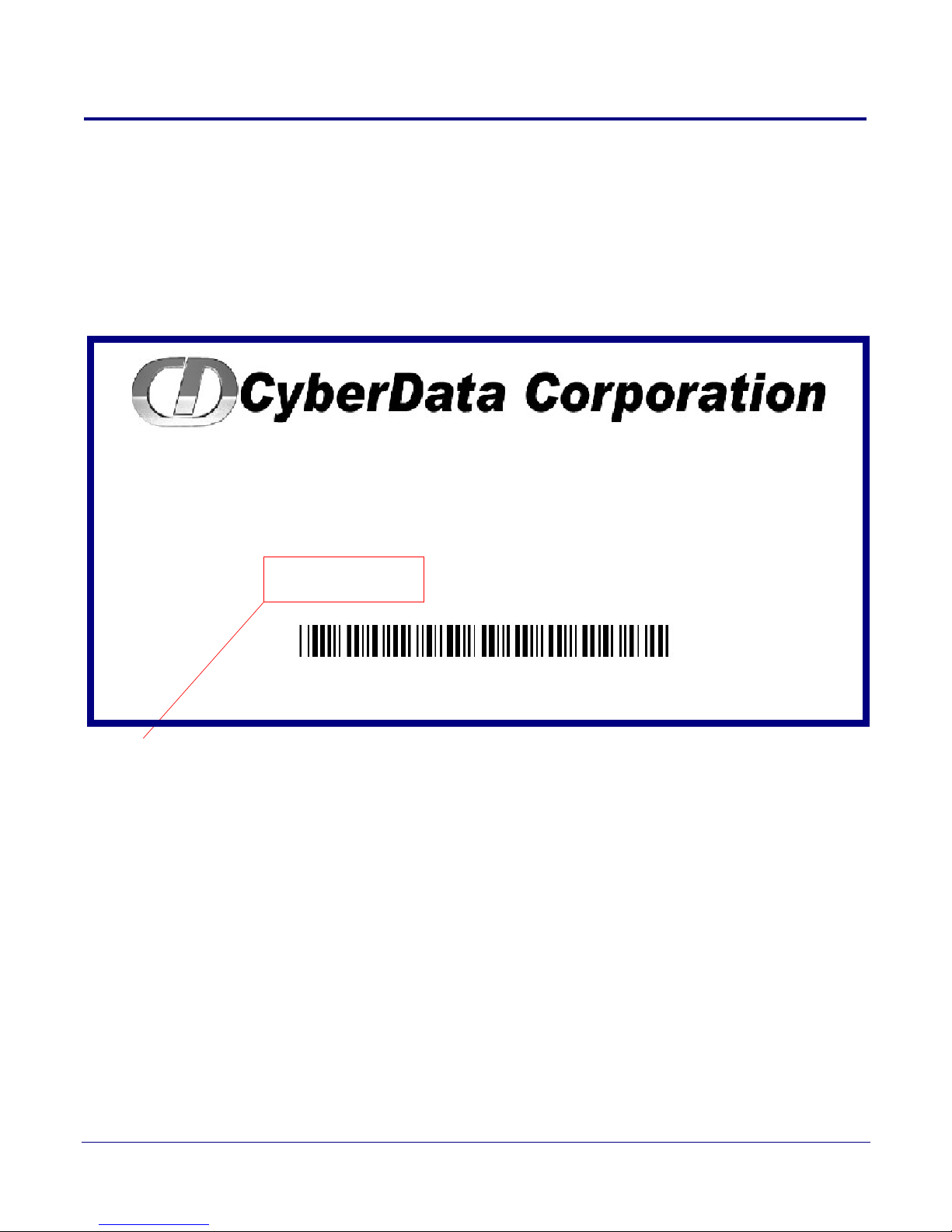
1.1 How to Identify This Product
SPEAKER,V2,VoIP INDOOR PAGING,
CEILING/WALL MOUNTED, RoHS
011098A / 021037C
WWW.CYBERDATA.NET
098000001
Model number
To identify the VoIP V2 Speaker, look for a model number label similar to the one shown
in Figure 1-1. The model number on the label should be one of the following:
• 011098*, RAL 9002, Gray White, Standard Color
• 011099, RAL 9003, Signal White, Optional Color
*Replaces 011021.
Figure 1-1. Model Number Label
Product Overview
How to Identify This Product
2
Operations Guide 930274I CyberData Corporation
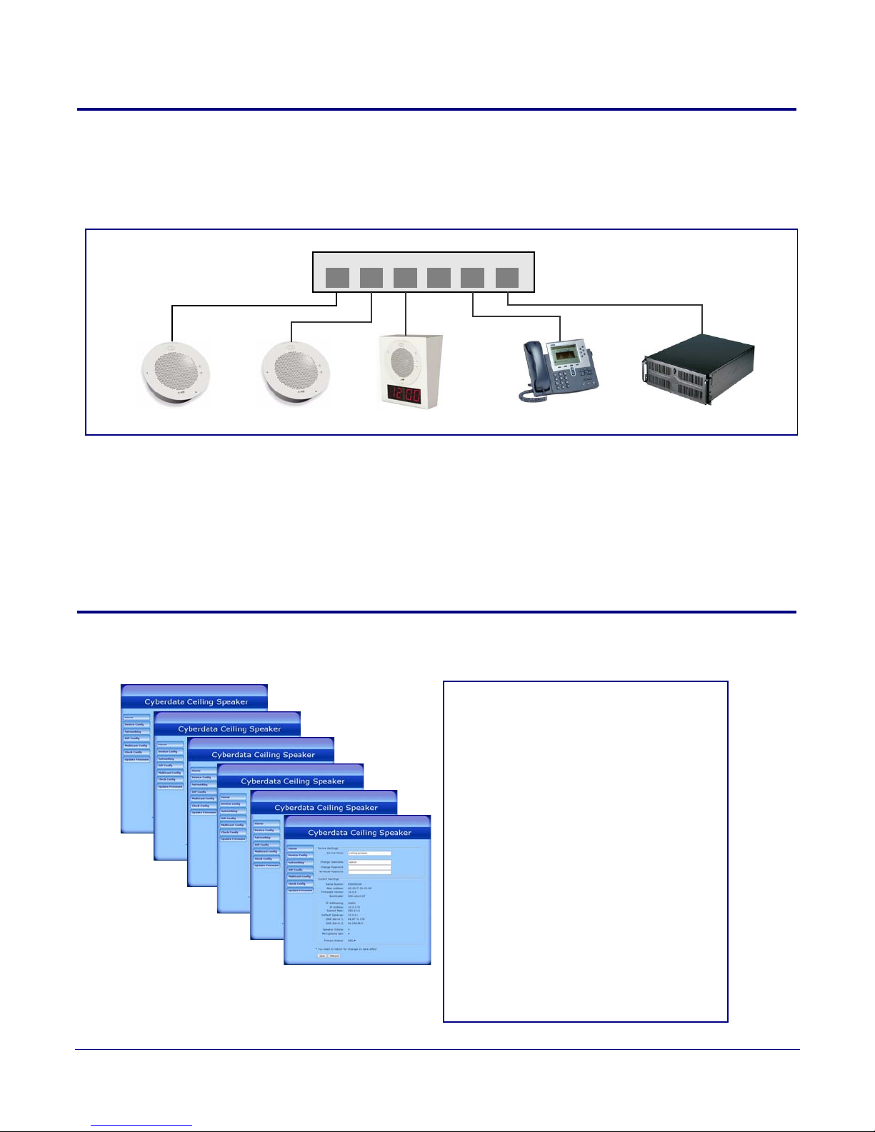
1.2 Installation
802.3af Compliant Ethernet Switch
Clock Kit
IP Phone IP PBX Server
12 34 56
Speaker
Speaker
• SIP (RFC 3261) compatible
• Web-based configuration
• Web-based firmware upgradeable
• Autoprovisioning support
• Small footprint
• High efficiency speaker driver
• PoE 802.3af Enabled (Powered-overEthernet)
• Network and external speaker volume
control
• Peer-to-peer capability
• User-uploadable ring and alert tones
• Auto detect for CyberData Clock kit
• Nightringer
•Buffered page
Figure 1-2 illustrates a typical configurations for the VoIP V2 Speaker.
See the following sections for other installation options:
• Section 2.2.1.3, "Running the V2 Speaker with Auxiliary Power"
• Section 2.2.2.1, "V2 Speaker with an External Device"
• Section 2.2.2.2, "V2 Speaker with Auxiliary Speaker Connection"
• Section 2.2.2.3, "V2 Speaker with Line Out"
Figure 1-2. Typical Installation
Product Overview
Installation
3
1.3 Product Features
Operations Guide 930274I CyberData Corporation

1.4 Supported Protocols
The V2 Speaker supports:
•SIP
•Multicast
• HTTP Web-based configuration
Provides an intuitive user interface for easy system configuration and verification of
speaker operations.
•DHCP Client
Dynamically assigns IP addresses in addition to the option to use static addressing.
• HTTP TCP Post auto-updating event notification in XML format
•TFTP Client
Facilitates hosting for the configuration file for Autoprovisioning.
•Audio Encodings
PCMU (G.711 mu-law)
PCMA (G.711 A-law)
Packet Time 20 ms
Product Overview
Supported Protocols
4
1.5 Supported SIP Servers
The following link contains information on how to configure the speaker for the supported SIP
servers:
http://www.cyberdata.net/support/server/index.html
Operations Guide 930274I CyberData Corporation

Product Overview
Product Specifications
1.6 Product Specifications
Table 1-1. Product Specifications
Category Specification
Audio sensitivity 96dB/1W/1M S.P. Level
Audio output 10 Watts Peak Power
Operating temperature -30 to 55 C (-22 to 131 F)
Ethernet port baud rate 10/100 Mbps
Protocol SIP RFC 3261 Compatible
Power Input (J1) PoE 802.3af (as per IEEE 802.3af standard from a UL-listed, LPS-rated limited power source)
44-57 VDC (48 VDC nominal) at 350mA
5
or Auxiliary Power Inputa
(Terminal Block J10)
Payload types G711, A-law and µ-law
Regulatory compliance FCC Class B, CE
Warranty 2 years limited
Dimensions 9” x 2.4”
Weight 2.8 lbs./shipping weight of 3.8 lbs.
Part number 011098*, RAL 9002, Gray White, Standard Color
12 VDC at 1A (from a UL-listed, LPS-rated power supply)
(1.3 kg/shipping weight of 1.7 kg)
011099, RAL 9003, Signal White, Optional Color
*Replaces 011021.
a.Auxiliary power input for use when PoE power is not available. 12 VDC @ 1A. Do not use auxiliary power input
when speaker J1 is connected to a PoE power source.
Operations Guide 930274I CyberData Corporation
1.7 Optional Connections (J9 and J10)
AUX SPEAKER (-)
AUX SPEAKER (+)
GND
LINE OUT (-)
LINE OUT (+)
+5V OUT
RELAY NO
RELAY COM
AUX POWER (-)
AUX POWER (+)
(+12VDC @ 1A)
J10
J9
*Auxiliary power input for use
when PoE power is not available.
12 VDC @ 1A.
Relay contacts rated at
30 VDC @ 1A.
5 VDC @ 100 mA.
Auxiliary 8-Ohm speaker
connection (not to be used
when the Clock is connected.
Audio line - level output to
external audio amplifier.
2v P-P into 10k Ohms.
*Do not use auxiliary power input when speaker J1 is connected to a PoE power source.
Function
FunctionJ10 Connections J9 Connections
Figure 1-3. Optional Connections (J9 and J10)
Product Overview
Optional Connections (J9 and J10)
6
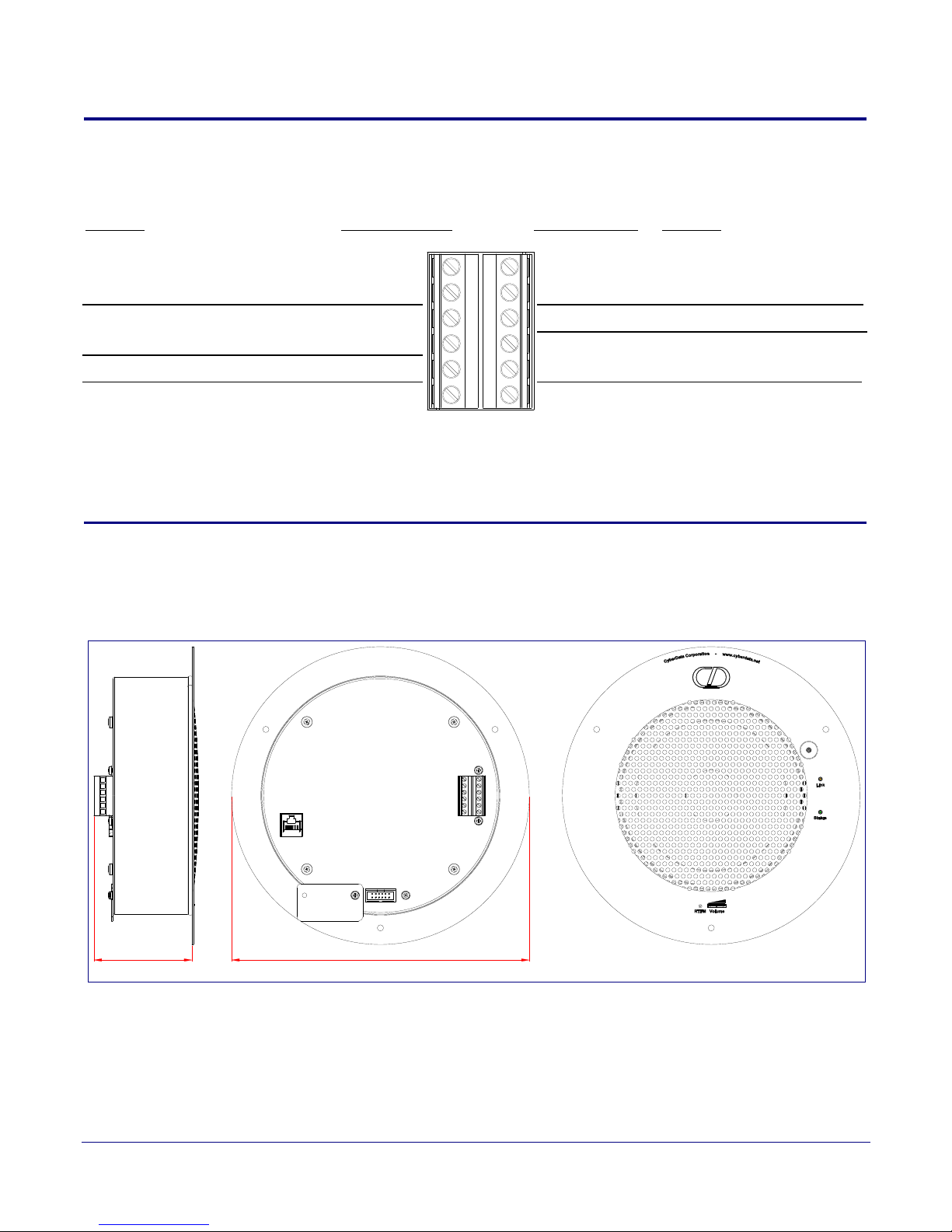
1.8 Dimensions
3.0 [75]
Figure 1-4 shows the dimensions for the V2 Speaker.
Figure 1-4. Dimensions
Dimensions are in Inches [Millimeter]
9.0 [229]
Operations Guide 930274I CyberData Corporation
2 Installing the VoIP V2 Speaker
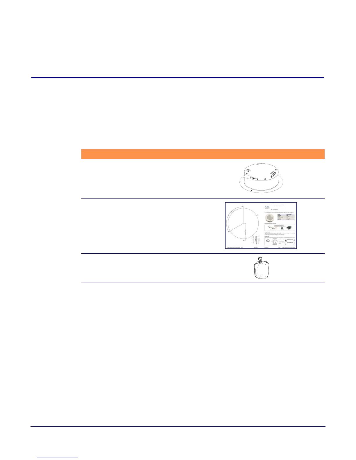
2.1 Parts List
Ta bl e 2-1 illustrates the parts for each speaker and includes kits for the drop ceiling and drywall
mounting.
Note The installation template for the V2 Speaker is located on the Installation Quick Reference
Guide that is included in the packaging with each speaker.
Table 2-1. Parts
Quantity Par t Name Illustration
1 V2 Speaker Assembly
7
1 Installation Quick Reference Guide
1 Speaker Mounting Accessory Kit
(Part #070054A)
Operations Guide 930274I CyberData Corporation

2.2 Device Configuration
Set up and configure each speaker before you mount it.
CyberData delivers each speaker with the following factory default values:
Table 2-2. Factory Network Default Settings—Default of Network
Param eter Factory Default Setting
IP Addressing DHCP
IP Address
Web Access Username admin
Web Access Password admin
Subnet Mask
Default Gateway
a
a
a
a. Default if there is not a DHCP server present.
10.10.10.10
255.0.0.0
10.0.0.1
Installing the VoIP V2 Speaker
Device Configuration
8
Operations Guide 930274I CyberData Corporation
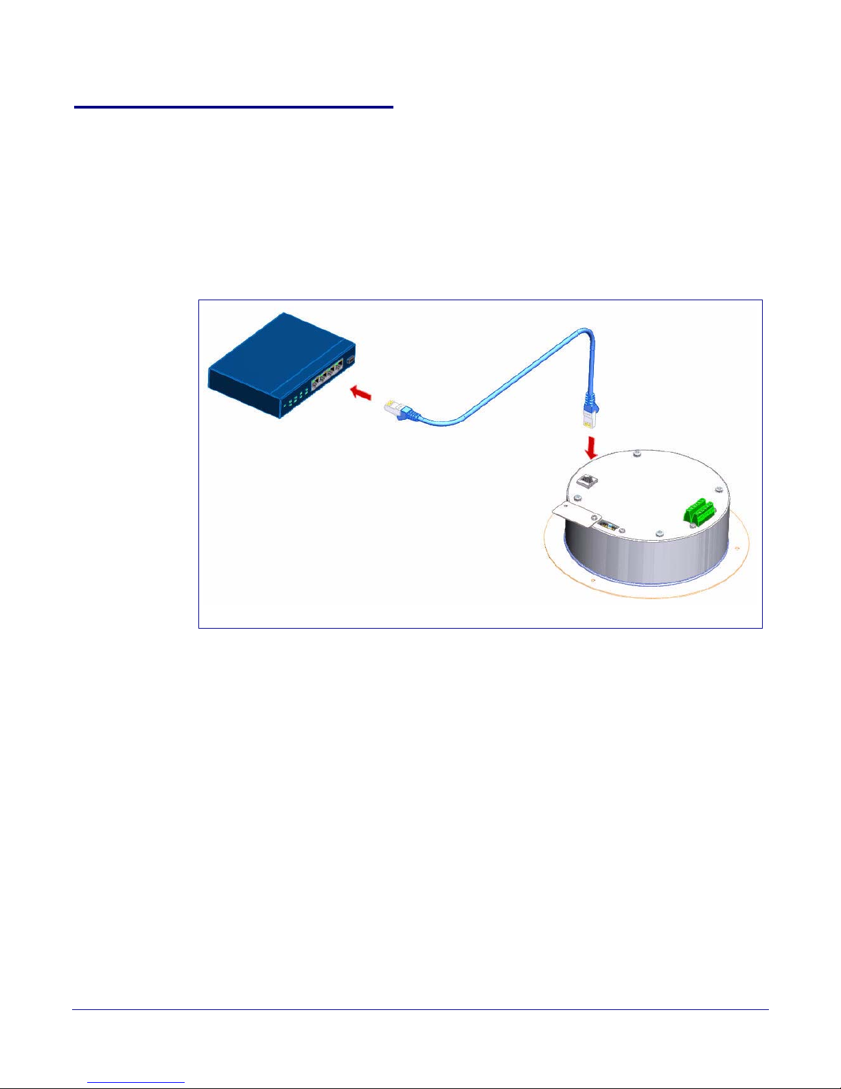
2.2.1 Connect Power to the Speaker
802.3af Compliant PoE Switch
Cat 5 Ethernet cable
VoIP V2 Speaker
Figure 2-1 through Figure 2-3 illustrates how to connect power to the VoIP V2 Speaker.
2.2.1.1 VoIP V2 Speaker to a 802.3af Compliant PoE Switch
Figure 2-1 illustrates how to connect the VoIP V2 Speaker to a 802.3af compliant PoE switch via a Cat
5 Ethernet cable.
Figure 2-1. VoIP V2 Speaker to a 802.3af Compliant PoE Switch
Installing the VoIP V2 Speaker
Device Configuration
9
Operations Guide 930274I CyberData Corporation
Installing the VoIP V2 Speaker
PoE Injector (Part #010867A)
Non PoE Switch
VoIP V2 Speaker
Cat 5 Ethernet cable
Device Configuration
2.2.1.2 VoIP V2 Speaker (with PoE Injector) to a 802.3af Compliant PoE Switch
In Figure 2-2, if a PoE switch is not available, you will need a PoE Injector, part #010867A (ordered
separately). A PoE Injector is a power supply solution for those who have a standard Non PoE
Switch.
Figure 2-2. VoIP V2 Speaker (with PoE Injector) to a Non PoE Switch
10
Operations Guide 930274I CyberData Corporation
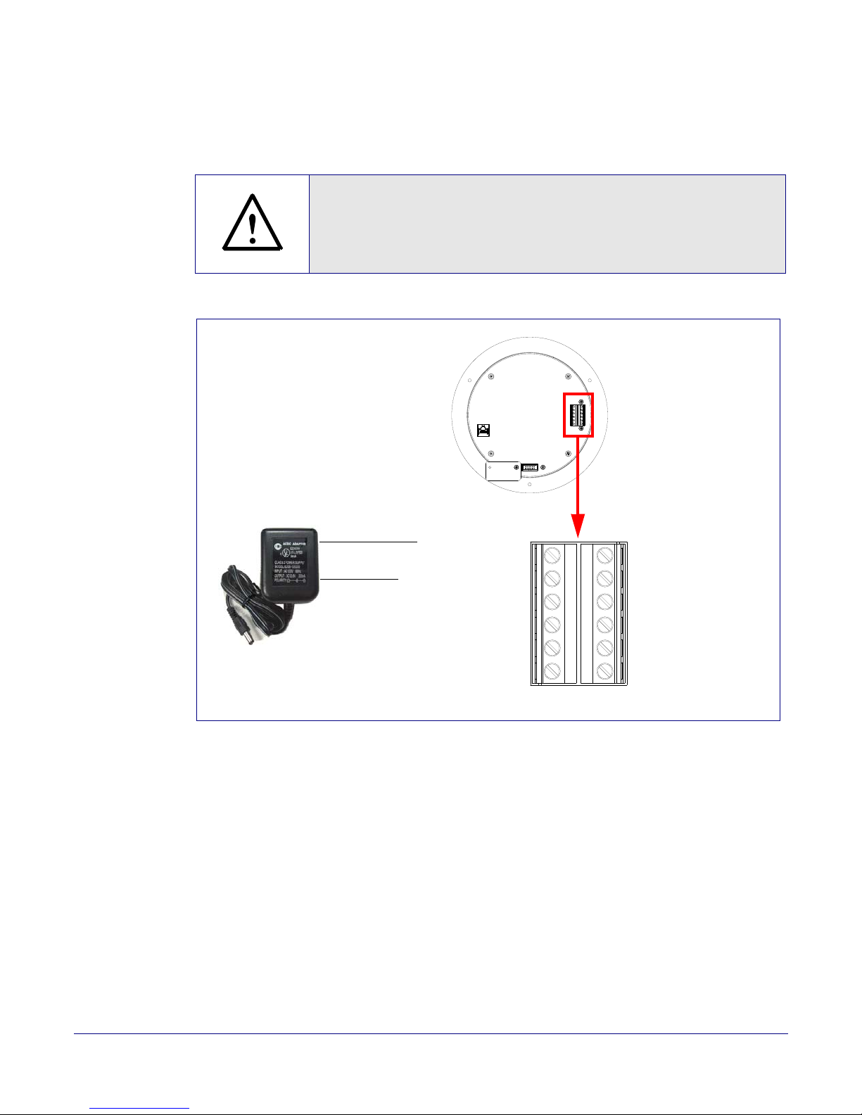
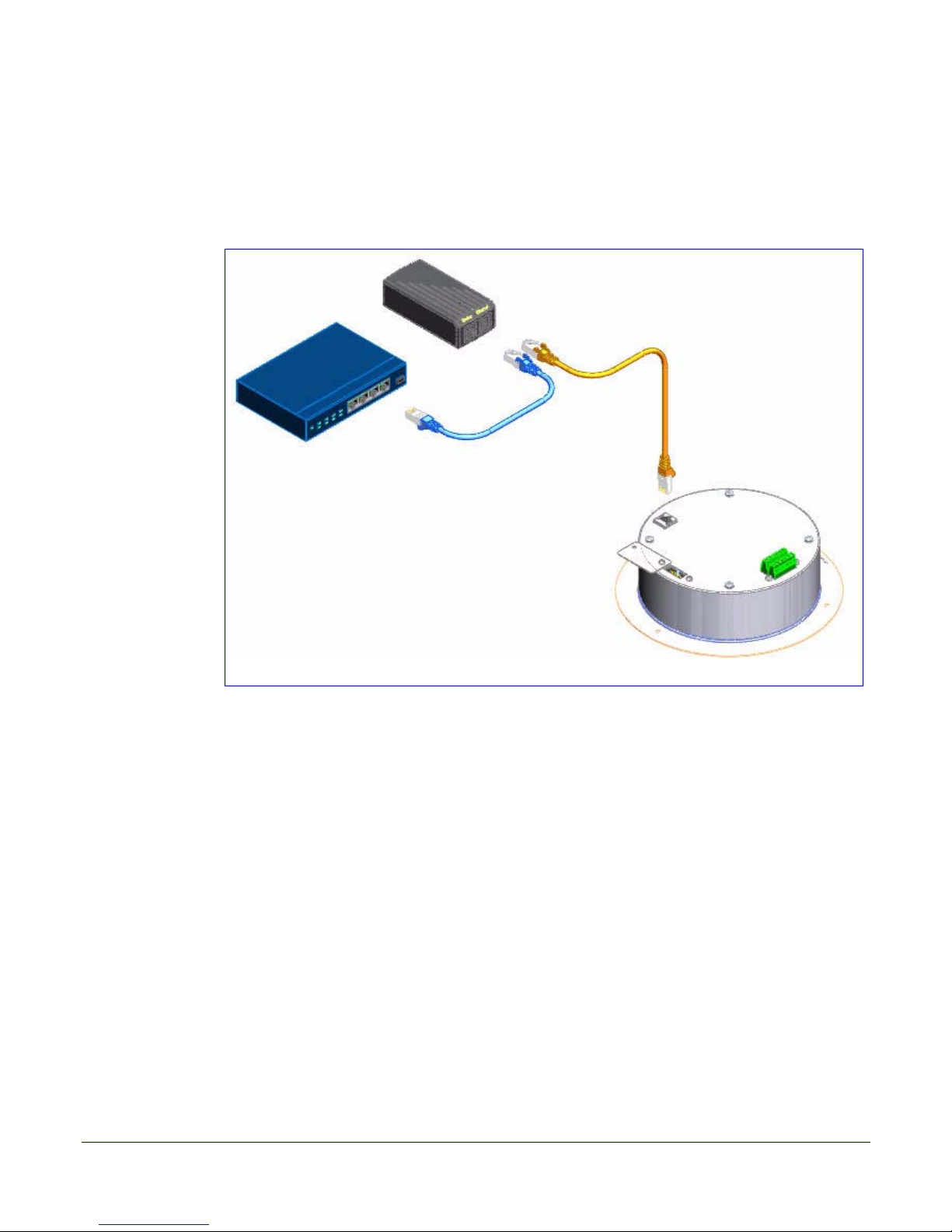
2.2.1.3 Running the V2 Speaker with Auxiliary Power
GENERAL ALERT
GND
AC adaptor
+12 VDC @ 1 Amps
(UL-listed, LPS-rated)
+12 VDC
Speaker
AUX SPEAKER (-)
AUX SPEAKER (+)
GND
LINE OUT (-)
LINE OUT (+)
+5V OUT
RELA Y NO
RELAY COM
AUX POWER (-)
AUX POWER (+)
(+12VDC @ 1A)
J10
J9
In Figure 2-3, the power for the V2 Speaker can either come from an 802.3af Network connection or
from an external source.
Caution
Operational Note: Do not connect an auxiliary power supply when th e V2
Speaker is connected to a PoE power source through J1. Improper operation or
equipment damage m ay occur .
Figure 2-3. Running the V2 Speaker with Auxiliary Power
Installing the VoIP V2 Speaker
Device Configuration
11
Operations Guide 930274I CyberData Corporation
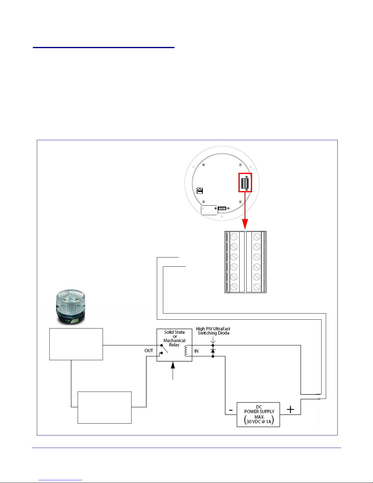
2.2.2 Installation Options
Alert Strobe
Speaker
External Device
Such as an
Electric Door Strike
or Strobe Light
AC or DC
Power Source
as Required by
an External Device
Output Contacts
AC or DC-rated
Depending Upon
External Device
Requirements
AUX SPEAKE R (-)
AUX SPEAKE R (+)
GND
LINE OUT (-)
LINE OUT (+)
+5V OUT
RELAY NO
RELAY COM
AUX POWER (-)
AUX POWER (+)
(+12VDC @ 1A)
J10
J9
This section shows various installation options for the V2 Speaker.
2.2.2.1 V2 Speaker with an External Device
In Figure 2-4, when the V2 Speaker is called from a remote phone, the relay on the speaker can be
programmed to drive an external device such as an alert strobe. This external device may also be
addressed from a separate Unified Communication (UC) server.
Figure 2-4. V2 Speaker with Alert Strobe
Installing the VoIP V2 Speaker
Device Configuration
12
Operations Guide 930274I CyberData Corporation
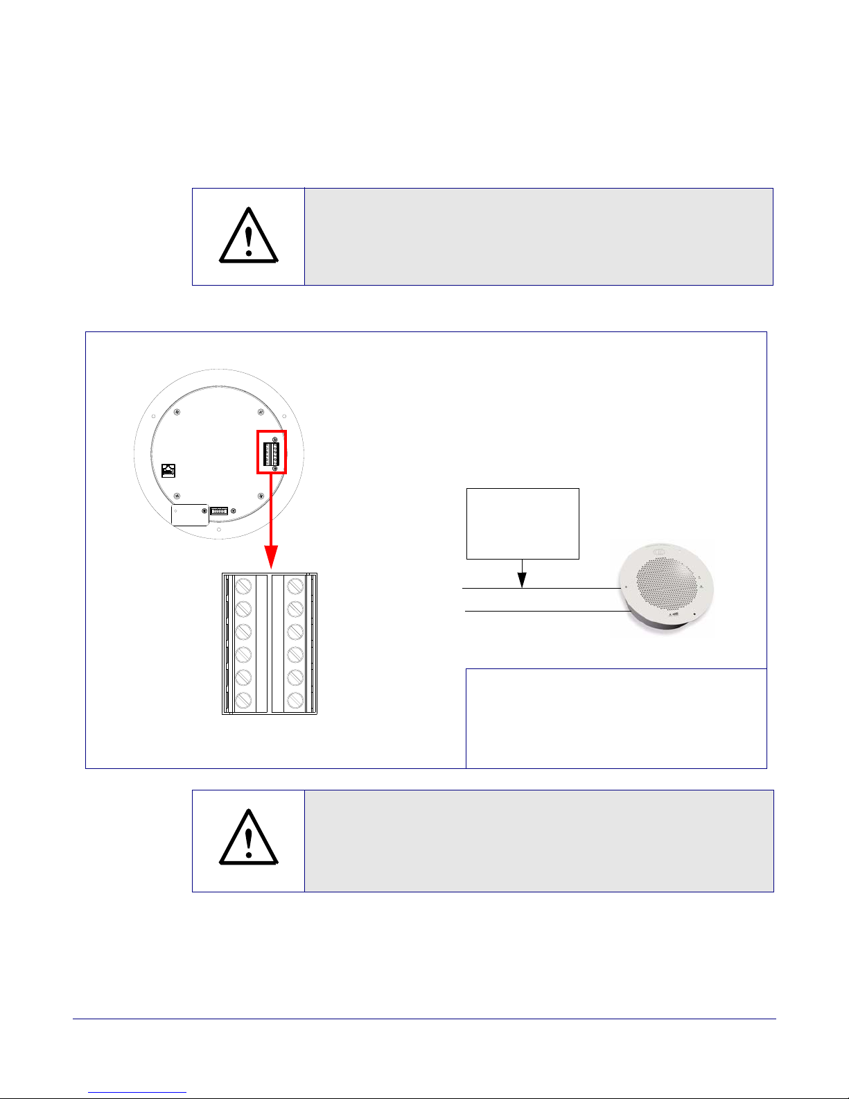
2.2.2.2 V2 Speaker with Auxiliary Speaker Connection
GENERAL ALERT
8 Ohm Auxiliary Speaker
High-purity copper
16-gauge wire and
a maximum length
of 20 feet
Speaker
(Part #011120, RAL 9002)
*When using the second speaker connection,
the analog volume control needs to be disabled.
*Because of the limitations of PoE power,
when running the V2 Speaker with a second auxiliary
speaker, the analog or digital volume level setting
must not exceed a setting of 6.
(Part #011121, RAL 9003)
AUX SPEAKER (-)
AUX SPEAKER (+)
GND
LINE OUT (-)
LINE OUT (+)
+5V OUT
RELA Y NO
RELAY COM
AUX POWER (-)
AUX POWER (+)
(+12VDC @ 1A)
J10
J9
GENERAL ALERT
In Figure 2-5, the V2 Speaker supports an amplified audio output for a second analog speaker. While
the total speaker wattage is the same, by connecting a low cost analog speaker, additional coverage
can be realized.
Caution
Operational Note: Be cause of the limitations of PoE power, when running the V2
Speaker with a sec ond auxi li ary spe aker, the analog or digital volume level setting
must not exceed a setti ng of 6.
Figure 2-5. V2 Speaker with Auxiliary Speaker Connection
Installing the VoIP V2 Speaker
Device Configuration
13
Operations Guide 930274I CyberData Corporation
Caution
Operational Note: You must not use the V2 Speaker in combination wit h both a
Clock Kit and an auxiliary speaker. The V2 Speaker may only be used separately
with an auxiliar y speaker or used separately with a Clock Kit. See Figure 2-6,
"Clock Kit with Extra Speaker Connection is NOT ALLOWED."
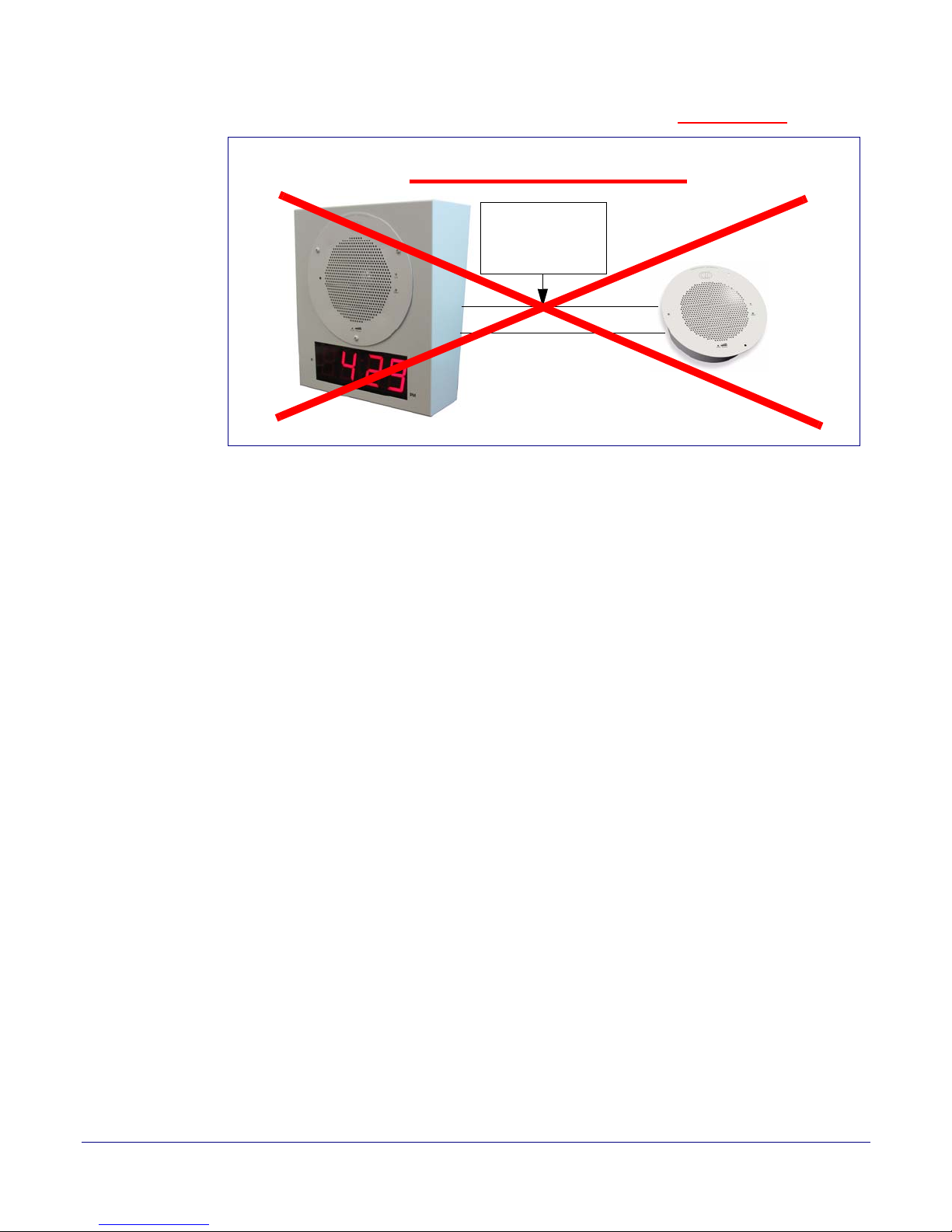
Installing the VoIP V2 Speaker
8 Ohm Analog Speaker
16 gauge wire and
a maximum length
of 20 feet
(CD Part Number 011072)
NOT ALLOWED
VoIP Clock Kit (Wall Mount Version)
Device Configuration
Figure 2-6. Clock Kit with Extra Speaker Connection is NOT ALLOWED.
14
Operations Guide 930274I CyberData Corporation
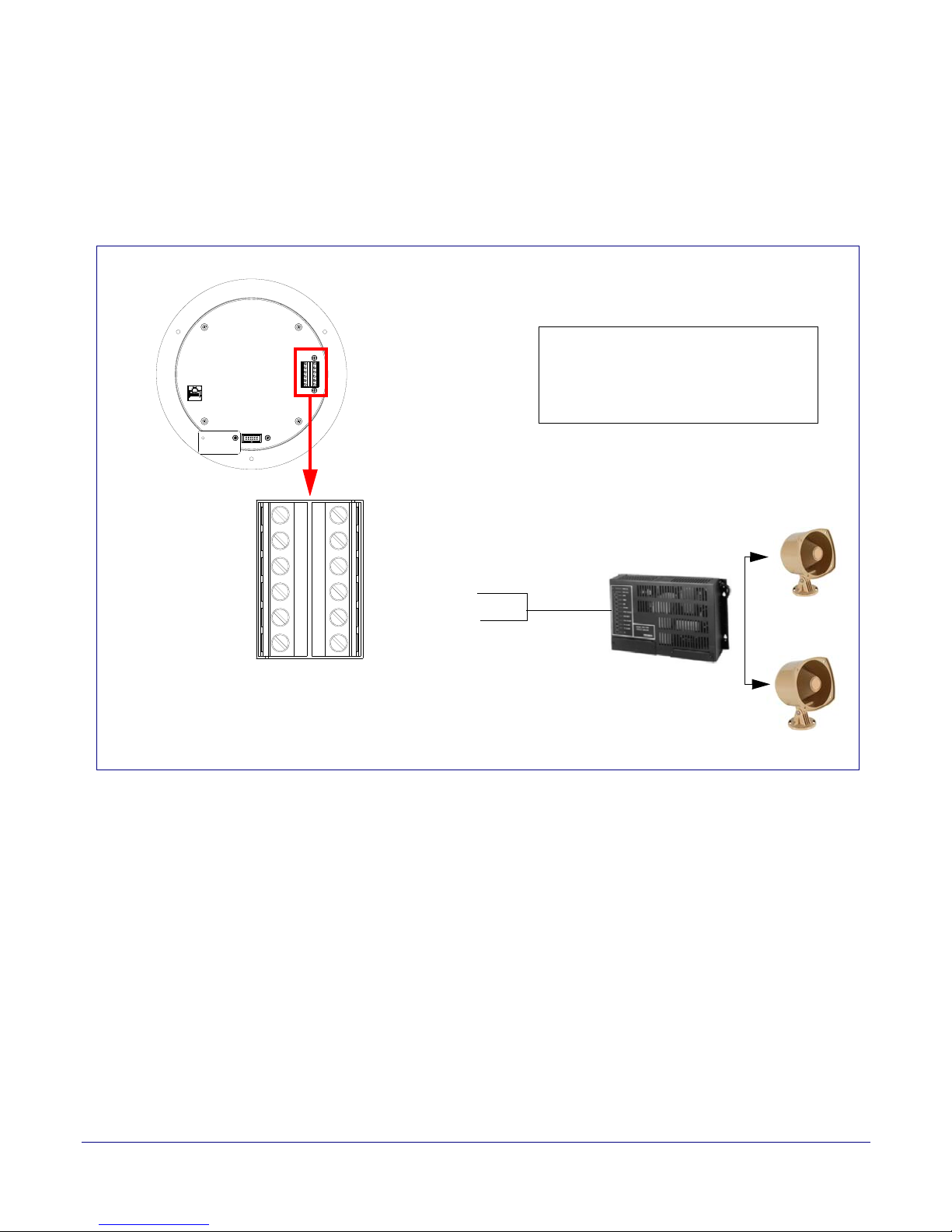
2.2.2.3 V2 Speaker with Line Out
Office area in Factory
Factory Floor
Amplifier
Line Out:
Output Signal Amplitudes 2.0 VPP maximum
Output Level +2dBm nominal
Total Harmonic Distortion 0.5% maximum
Output Impedance 10k ohm
Speaker
AUX SPEAKER (-)
AUX SPEAKER (+)
GND
LINE OUT (-)
LINE OUT (+)
+5V OUT
RELAY NO
RELAY COM
AUX POWER (-)
AUX POWER (+)
(+12VDC @ 1A)
J10
J9
In Figure 2-7, for areas that require more speaker volume, the V2 Speaker can be connected directly
to an auxiliary amplifier to drive additional horns or speakers. This is done through the line-out
connection.
Figure 2-7. V2 Speaker with Line Out
Installing the VoIP V2 Speaker
Device Configuration
15
Operations Guide 930274I CyberData Corporation
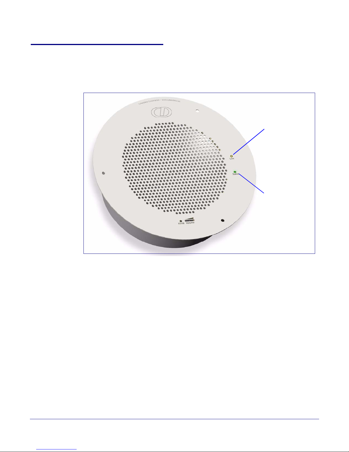
Installing the VoIP V2 Speaker
Speaker
Status
(Green)
Network
Link/Activity
(Yellow)
Device Configuration
2.2.3 Confirm that the Speaker is Operational and Linked to the Network
After connecting the speaker to the 802.3af compliant Ethernet hub, the LEDs on the speaker face
confirm that the speaker is operational and linked to the network.
Figure 2-8. Status and Activity LEDs
16
2.2.3.1 Status LED
After supplying power to the speaker:
1. The green power/status LED and the yellow network LED comes on immediately.
2. After about 23 seconds with a static IP address (or 27 seconds if the board is set to use DHCP),
the green LED will blink twice to indicate that the board is fully booted. The speaker will beep
at this time if the
Beep on Initialization option is enabled on the Device Configuration Page
(see Section 2.3.3, "Configure the Device Parameters").
Note If the board is set to use DHCP and there is not a DHCP server available on the network, it
will try 12 times with a three second delay between tries and eventually fall back to the
programmed static IP address (by default 10.10.10.10). This process will take approximately
80 seconds.
Note The front power/status LED will remain solid on during operation.
2.2.3.2 Link LED
•The Link LED is illuminated when the network link to the speaker is established.
•The Link LED blinks to indicate network traffic.
Operations Guide 930274I CyberData Corporation
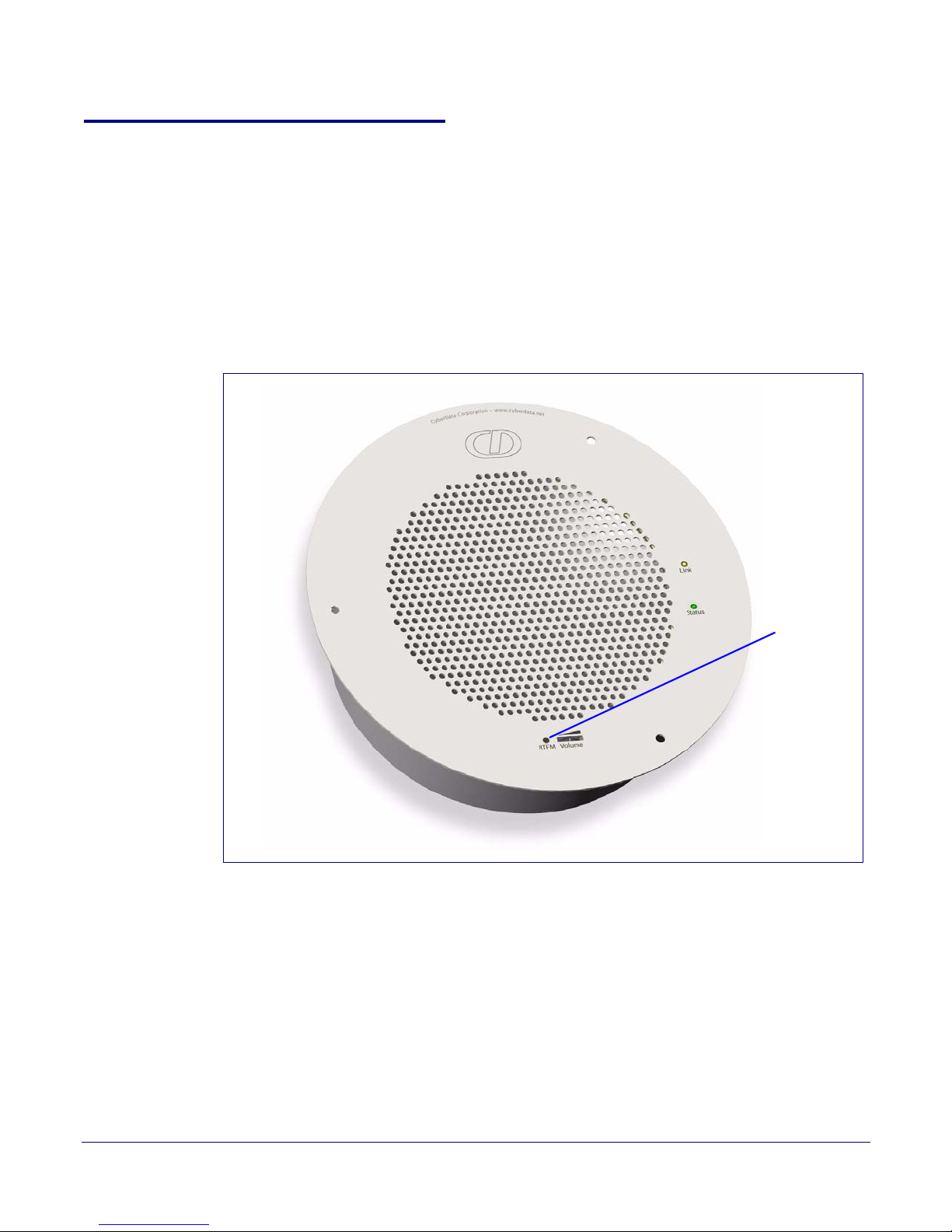
2.2.4 Confirm the IP Address and Test the Audio
RTFM switch
2.2.4.1 Reset Test Function Management (RTFM) Switch
When the speaker is operational and linked to the network, use the Reset Test Function
Management (RTFM) switch (
IP Address and test that the audio is working.
Note Using the RTFM switch will lock the digital volume level to 4 and disable the analog
volume control dial.
Figure 2-9) on the speaker face to announce and confirm the speaker’s
Figure 2-9. RTFM Switch
Installing the VoIP V2 Speaker
Device Configuration
17
To announce a speaker’s current IP address, press and release the RTFM switch within a five second
window.
Note The speaker will use DHCP to obtain the new IP address (DHCP-assigned address or
default to 10.10.10.10 if a DHCP server is not present).
Note Pressing and holding the RTFM switch for longer than five seconds will restore the speaker
to the factory default settings.
Operations Guide 930274I CyberData Corporation
 Loading...