

Page 1
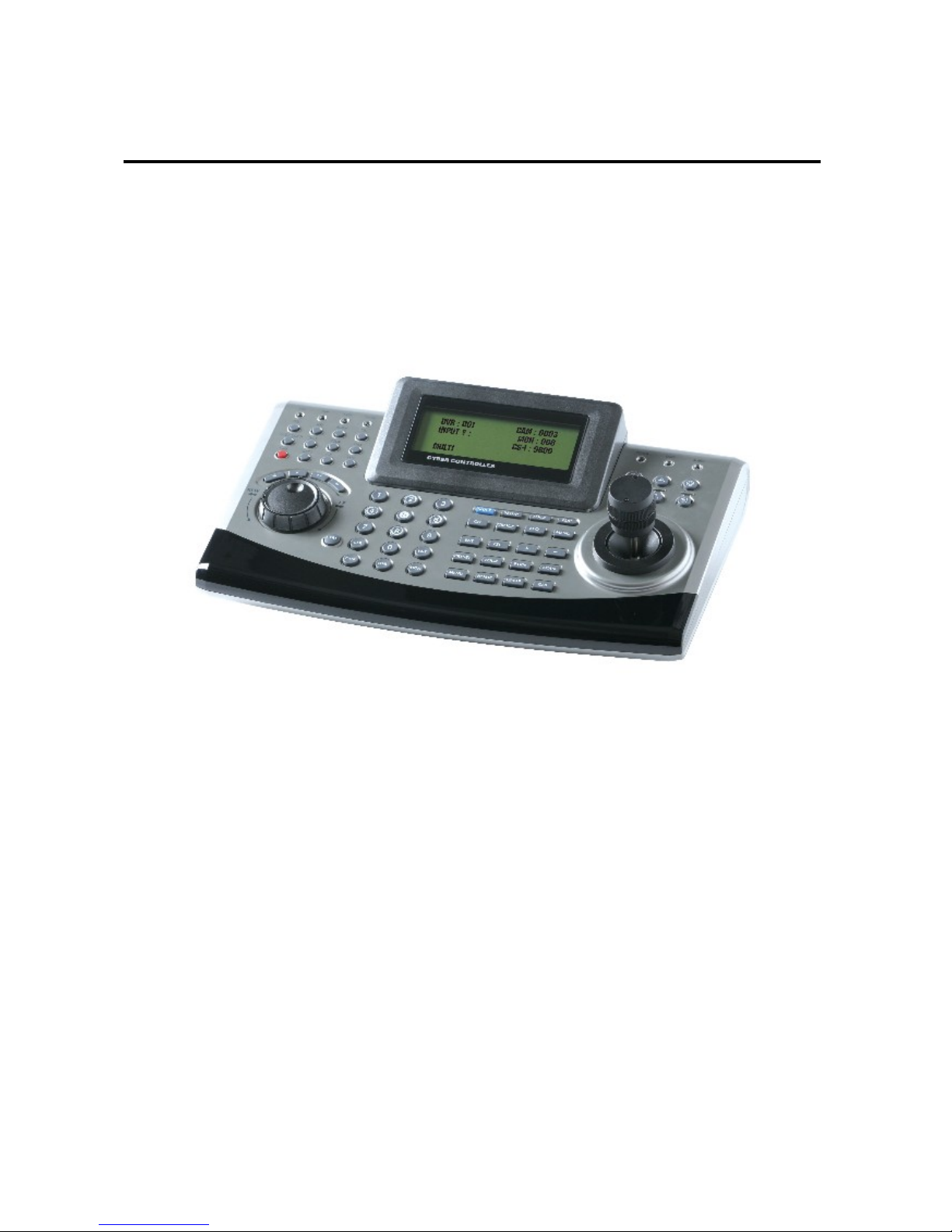
Cyber Controller
INSTRUCTION MANUAL
Please read this manual thoroughly before use and keep it handy for future reference.
Page 2
WARNINGS and CAUTIONS
WARNINGS
x TO REDUCE THE RISK OF FIRE OR ELECTRIC SHOCK.
- DO NOT EXPOSE THIS PRODUCT TO RAIN OR MOISTURE.
- DO NOT INSERT ANY MEALMETALLIC OBJECTS THROUGH THE VENTILATION GRILLS OR OTHERS
OPENINGS ON THE EQUIPMENT.
CAUTIONS
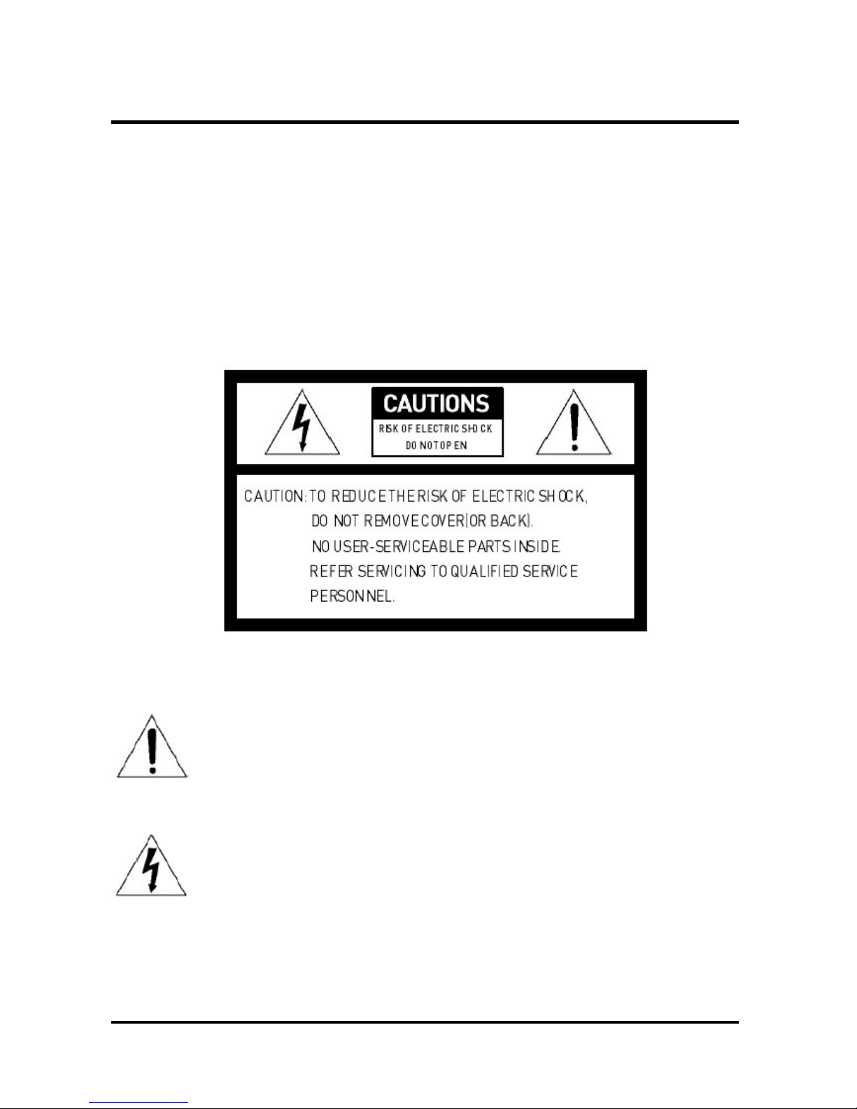
EXPLANATION OF GRAPHICAL SYMBOLS
The lighting flash with arrowhead symbol, within a triangle, is intended to alert the user
to the presence of un-insulated “dangerous voltage” within the product’s enclosure that
may be of sufficient magnitude to constitute a risk of electric shock to persons.
The exclamation point within an equilateral triangle is intended to alert the user to the
presence of important operating and maintenance (servicing) instruction in the literature
accompanying the product.
2
Page 3
COMPLIANCE STATEMENT
FCC INFORMATION : THIS EQUIPMENT HAS BEEN TESTED AND FOUND TO COMPLY WITH THE LIMITS
FOR A CLASS A DIGITAL DEVICE, PURSUANT TO PART 15 OF THE FCC RULES. THESE LIMITS ARE
DESIGNED TO PROVIDE REASONABLE PROTECTION AGAINST HARMFUL INTERFERENCE WHEN THE
EQUIPMENT IS OPERATED IN A COMMERCIAL ENVIRONMENT. THIS EQUIPMENT GENERATES, USES, AND
CAN RADIATE RADIO FREQUENCY ENERGY AND IF NOT INSTALLED AND USED IN ACCORDANCE WITH
THE INSTRUCTION MANUAL, MAY CAUSE HARMFUL INTERFERENCE TO RADIO COMMUNICATIONS.
OPERATION OF THIS EQUIPMENT IN A RESIDENTIAL AREA IS LIKELY TO CAUSE HARMFUL INTERFERENCE
IN WHICH CASE THE USER WILL BE REQUIRED TO CORRECT THE INTERFERENCE AT HIS OWN EXPENSE.
CAUTION : CHANGES OR MODIFICATIONS NOT EXPRESSLY APPROVED BY THE PARTY RESPONSIBLE FOR
COMPLIANCE COULD VOID THE USER’S AUTHORITY TO OPERATE THE EQUIPMENT.
THIS CLASS A DIGITAL APPARATUS COMPLIES WITH CANADIAN ICES-003.
CET APPAREIL NUMERIQUE DE LA CLASSE A EST CONFORME A LA NORME NMB-00 3 DU CANADA.
CE COMPLIANCE STATEMENT
WARNING
THIS IS A CLASS A PRODUCT. IN A DOMESTIC ENVIRONMENT THIS PRODUCT MAY CAUSE RADIO
INTERFERENCE IN WHICH CASE THE USER MAY BE REQUIRED TO TAKE ADEQUATE MEASURES.
3
Page 4

IMPORTANT SAFEGUARDS
Please install the product on a completely flat floor.
- Always check the strength and stability of the installation location.
- Do not drop the appliance on the floor. This may result in damage or injury.
Do not attempt to disassemble the appliance. To prevent electric shock, do not remove screws or
covers.
- There are no user-serviceable parts inside. Contact qualified service personnel for
maintenance.
Stop using the appliance if there appears to be any operational problem.
- Immediately turn the power off to the appliance if there is any abnormal condition such as
smoke or unusual smells.
- Continuing to use the appliance under abnormal conditions may result in serious damage.
Always use the recommended power.
- Using incorrect power source ratings may result in fire, electric shock, or damage.
Always handle the connection cable with care.
- Never damage or modify the connection cable.
- Do not pull, expose to heat, or place heavy objects on the connection cable.
- Non-observance of these warnings may result in fire, electric shock or damage.
Never use the appliance in places where there are flammable materials.
- Never use the appliance in places where flammable materials such as gas are used.
This may result in fire, explosion, and other serious accidents.
Never touch un-insulated parts with wet hands.
- Touching un-insulated parts with wet hands may result in serious electric shock.
Never expose the appliance to water or moisture.
- If the appliance gets wet, immediately turn the power off.
- Stop using the appliance if it gets wet. Contact the manufacturer immediately.
Use the appliance indoors only.
- Do not place the appliance outdoors or expose it to rain or moisture.
- If dropped in water, the appliance may be corroded and damage.
Do not use the appliance where there is excessive dust, smoke, or moisture.
- Using the appliance under such conditions may result in fire, electric shock or serious damage.
If the controller body gets dirty, turn the power off and wipe the surface with a soft cloth.
- Do not use chemical agents such as alcohol or benzene.
4
Page 5

TABLE of CONTENTS
WARNINGS AND CAUTIONS 2
COMPLIANCE STATEMENT
3
CE COMPLIANCE STATEMENT
IMPORTANT SAFEGUARDS
4
1. INTRODUCTION
6
2. PACKAGE CONTENTS 7
3. INSTALLATION CONFIGURATION
8
3.1 Basic Configuration of DVR & Cyber Controller 8
3.2 Basic Configuration of Matrix System & Cyber Controller
9
3.3 The Example of Multi Configuration 10
4. OPERATING CONTROLS 11
4.1 Front View 11
4.2 Rear View 12
4.3 Operation by Part 13
5. OPERATION 16
5.1 POWER 16
5.2 DVR, Camera ID & Monitor NO. Selection 16
5.3 SYSTEM SETUP 17
5.3.1 SYSTEM INFO 17
5.3.2 PASSWORD SETUP 18
5.3.3 BACK LIGHT TIME 19
5.3.4 FACTORY DEFAULT 19
5.3.5 SYSTEM RESET 19
5.3.6 CAMERA SETUP 20
5.3.7 DVR SETUP 22
5.4 LOCK 24
5.4.1 LOCK SETTING 24
5.4.2 LOCK CANCEL 24
6. DIMENSION 25
7. SPECIFICATION 26
APPENDIX A – The List of GLB(Short) Key
27
APPENDIX B – Trouble Shooting
29
APPENDIX C – OPTIONAL ITEM
30
5
Page 6

1. INTRODUCTION
The Cyber Controller, Cyber Scan Dome, Video Matrix System & Digital Video Recorder make up the
building blocks for any surveillance/security system. Using a multiple Cyber Controller and multiple
dome cameras, no place is too large for monitoring and recording. Extendable and flexible
architecture facilitates remote control functions for a variety of external switching devices such as
DVR, Matrix System and Cyber Scan Dome Camera.
FEATURES
* 128 Monitor Control, 255 DVR Control, 999 Camera Control
* Built in Jog shuttle for easy playback
* Built in joystick for easy control of Zoom In/Out, Pan/Tilt
* Multi Protocol Built In (Cyber Scan (I,II) / P-D / P-P)
* Easy extension up to 6 different slave controller (Recommendable)
* RS-485/422 Communications (Max. 1.2Km)
* LED indicator for power, alarm, communication input etc.
How to operate with Cyber Controller?
1) Cyber Scan Dome Camera
* Built in 3 Axis Joystick
* Built in Pan/Tilt, Zoom In/Out Controls
* Focus Near/Far, IRIS Open/Close
* Main Menu Set Up Available
* Preset, Auto Scan, Tour and Pattern Controls
* RS-485 or RS-422 Operation
* Easy Wiring Connection and Operation
* Quick Preset Set Up and Recall
2) DVR Control (4Ch, 9Ch and 16Ch)
* Built in Jog shuttle
* Various Function Key t o control DVR
* Image Sequence/Multi Screen/Freeze/ESC/Menu Available
* Control REC, STOP, Reverse Playback, Play Button
* Main Menu Set Up Available
* Multi Camera Control Available (Max. 999)
* Direct Connection from Junction box for easy wiring
* Slave Controller Extendable
6
Page 7
1. INTRODUCTION
3) Video Matrix System (16Ch, 32Ch)
* 16Ch Input 4 Monitor Output / 32Ch Input 8 Monitor Output
* 16Ch Alarm Input (1U, Alar m Device as an accessory)
* 32Ch Alarm Input (2U,Built in the case)
* Direct Connection with DVR, VDA etc
* Easy extension using RJ-45 Cable
* RS-422/485 PTZ Connection and RS-232 PC Control
* Equal video strength for all outputs
* Color or B&W compatible
Precautions for proper Operation
* Do not install the unit a place subject to direct sunlight, excessive moisture, dust or vibrations
where ventilation is poor.
* Please use the unit in the range of a guarantee temperature and humidity of operation.
* Please set ID of a camera as the same number as the input channel to DVR.
2. PACKAGE CONTENTS
The Cyber Controller contains the following.
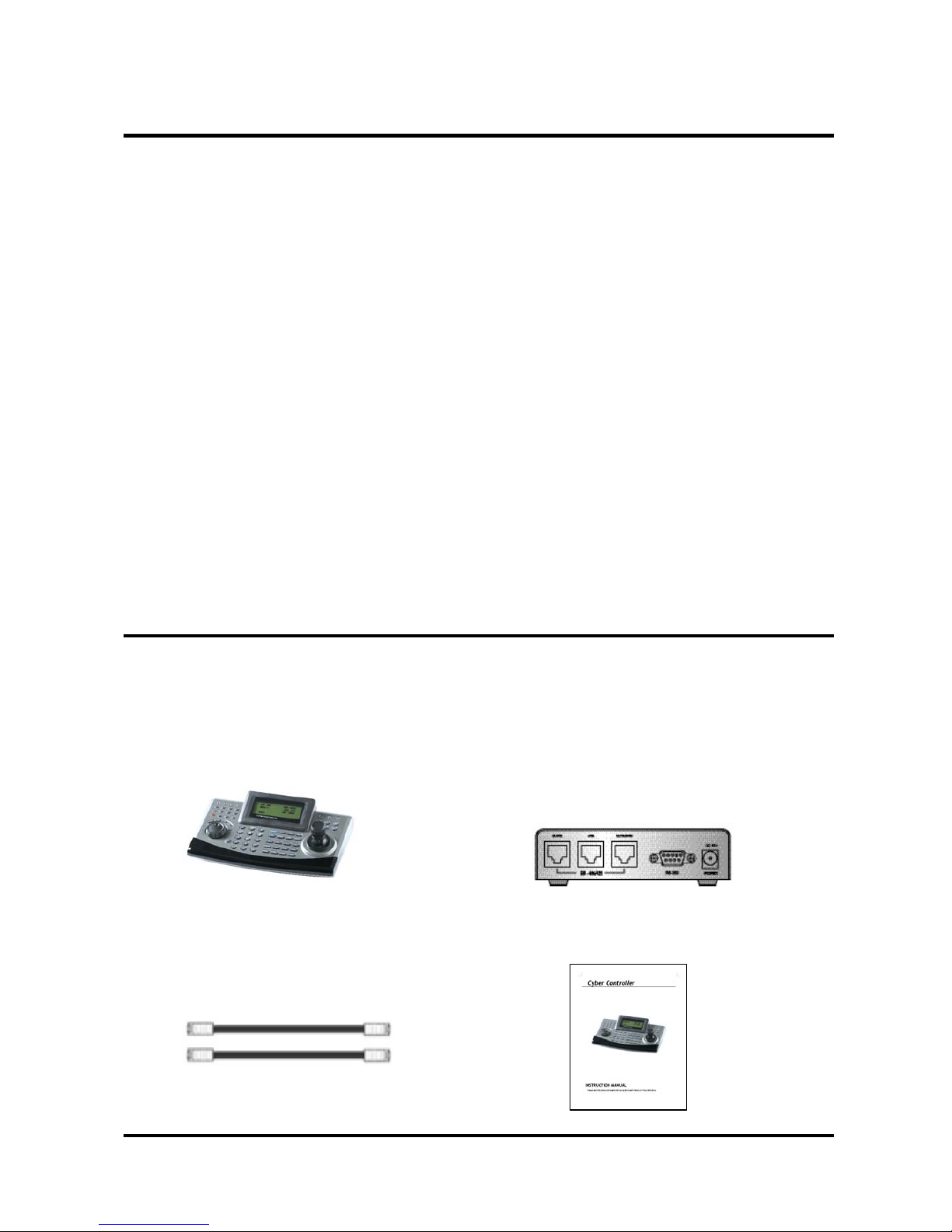
① Cyber Controller Unit ------- 1 ② Junction Box ------- 1
③ RJ-45 Cable ------- 2 ④ Instruction Manual ----- 1
7
Page 8
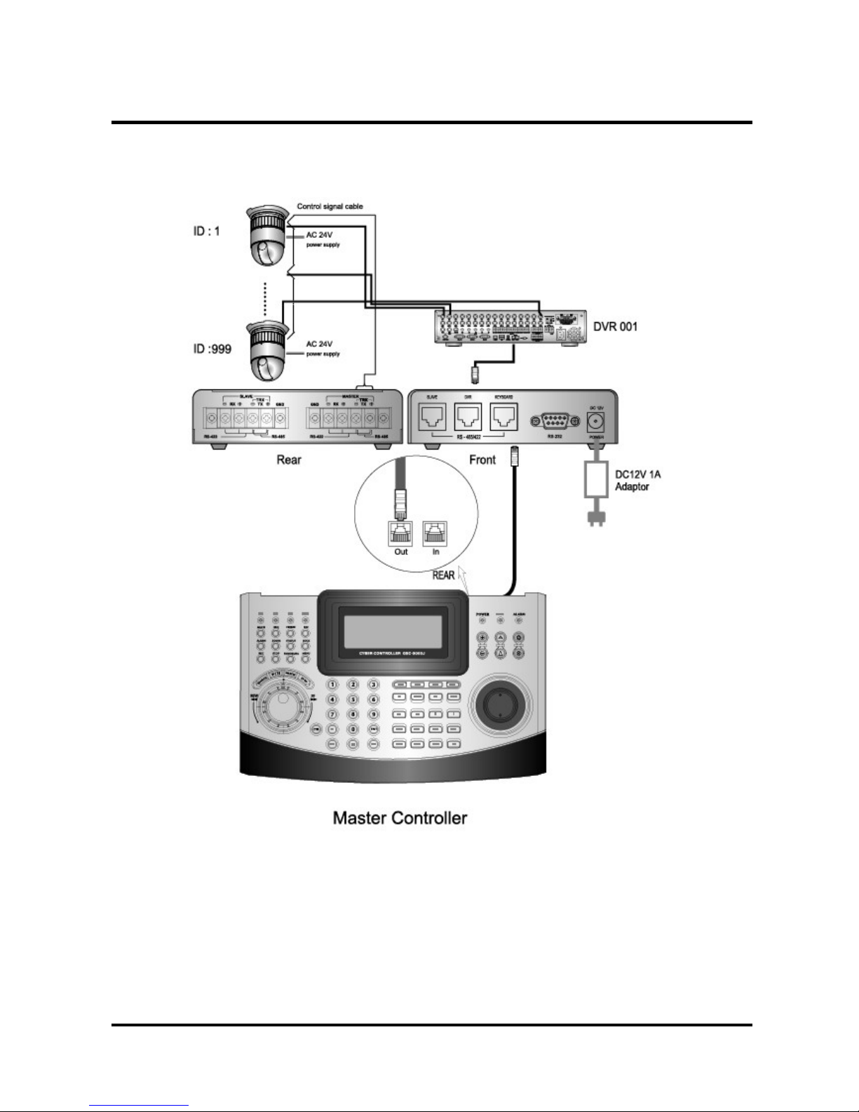
3. INSTALLATION & CONFIGURATION
3.1 Basic Configuration of DVR & Cyber Controller
8
Junction Box
Page 9
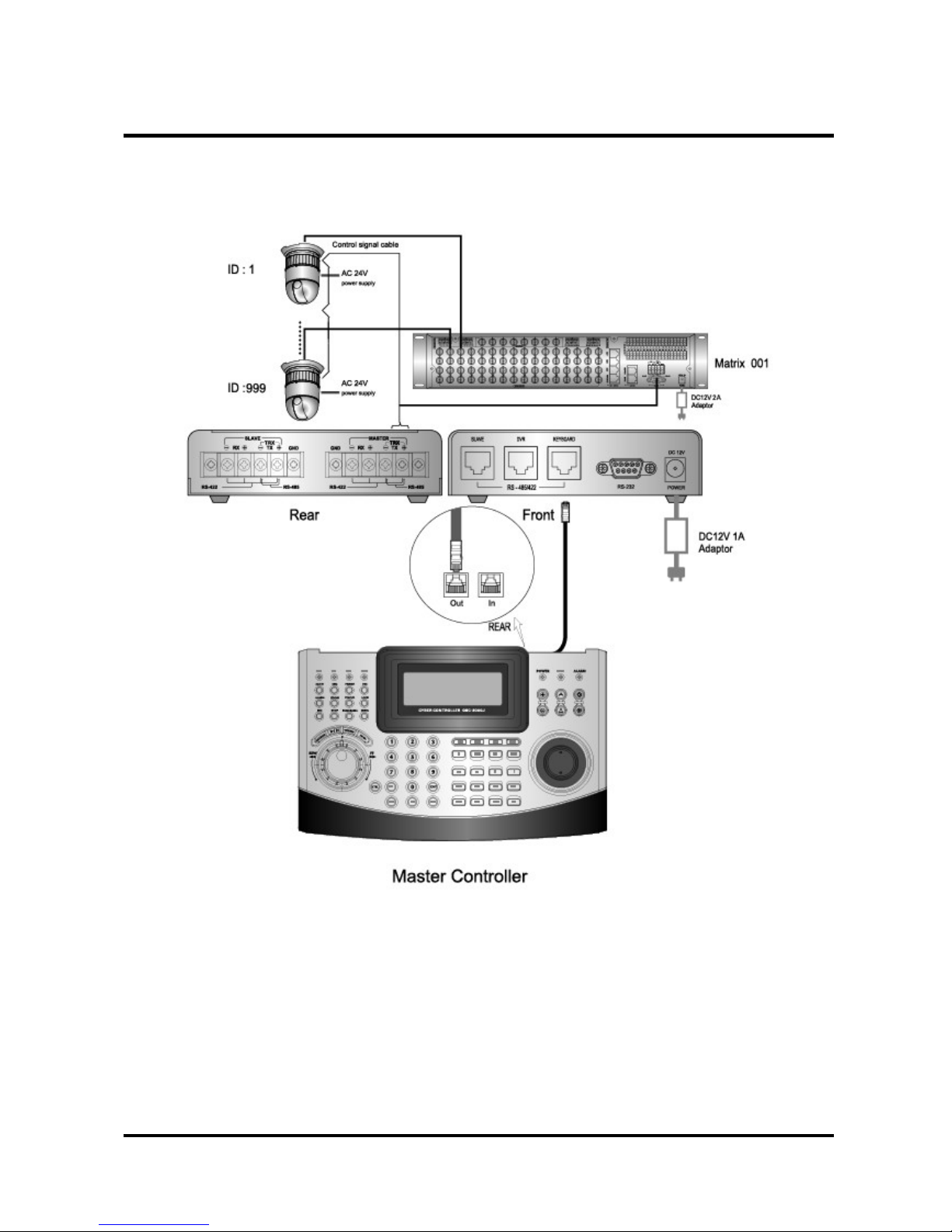
3. INSTALLATION & CONFIGURATION
3.2 Basic Configuration of Matrix System & Cyber Controller
9
Junction Box
Page 10
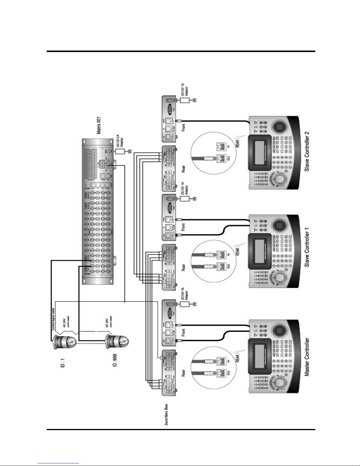
3. INSTALLATION & CONFIGURATION
3.3 The Example of Multi Configuration
10
Page 11
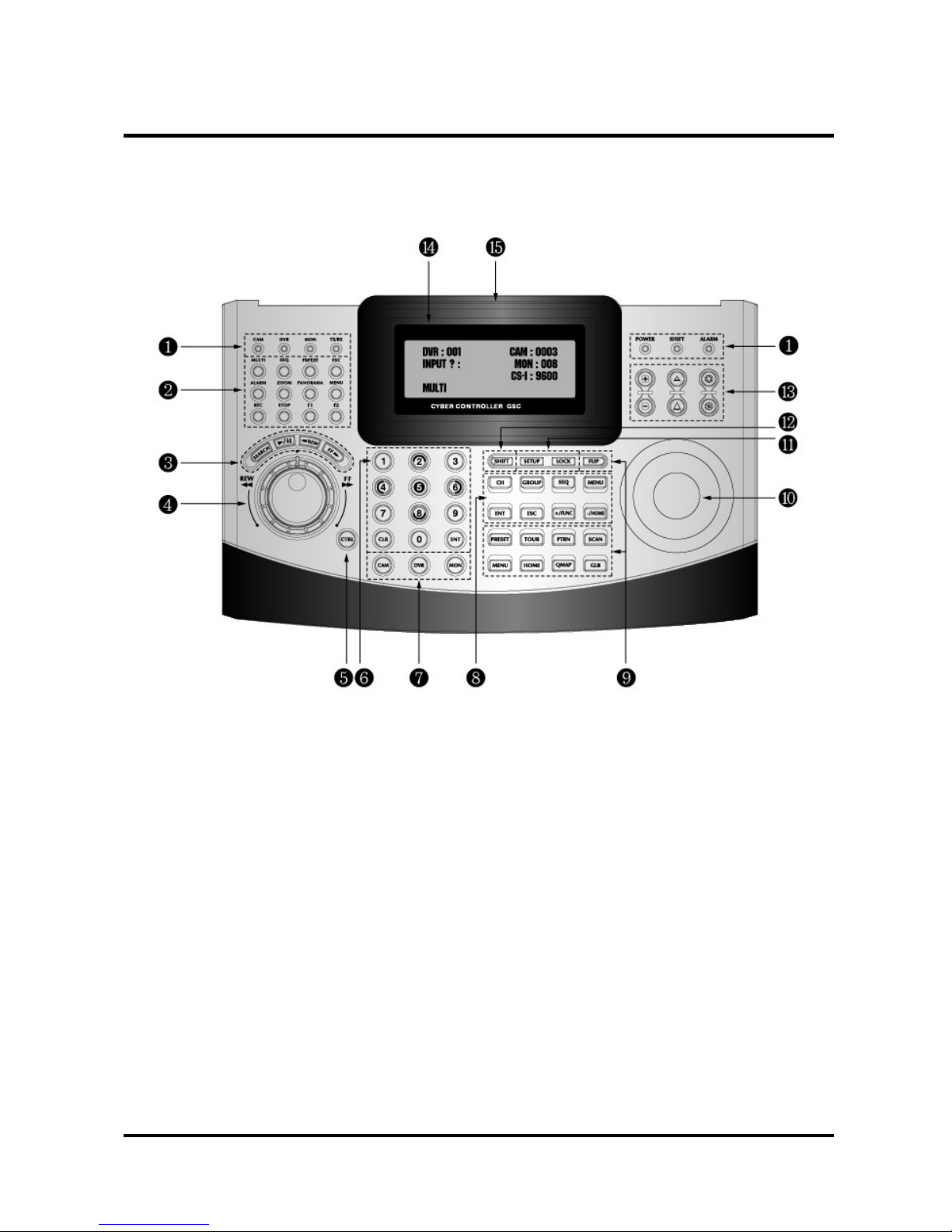
4. OPERATING CONTROLS
4.1 Front View
① LED Indicator ⑨ PTZ Keypad
② DVR Keypad ⑩ Joy Stick
③ DVR Playback ⑪ Controller Keypad
④ Jog Shuttle ⑫ SHIFT Button
⑤ CTRL Button ⑬ Zoom/Focus/IRIS
⑥ Numeric Button ⑭ 4 Line LCD
⑦ Special Key ⑮ Brand Logo
⑧ Matrix Keypad
11
Page 12
4. OPERATING CONTROLS
4.2 Rear View
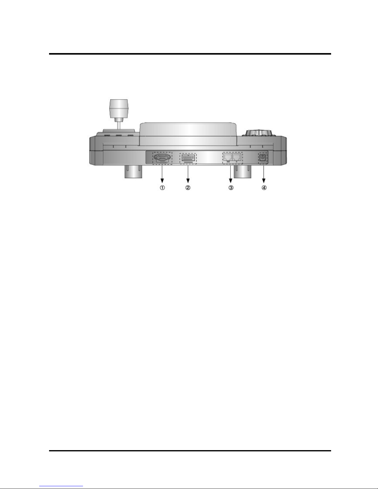
① RS-232 : This connector port is provided to connect the external modem for remote
monitoring, configuration and software upgrades. Use a modem cable with
ADB-9S(female) connector to connect to the Cyber controller.
Notice : A Modem cable not supplied so make certain you have the correct cable when you
connect to the Cyber controller.
② ID DIP Switch : It is used to select Cyber controller ID.
③ RJ-45 JACK (IN/OUT)
IN : Data Input port from the slave controller.
OUT : Data output port to the another devices, dome camera, matrix, DVR etc.
④ DC 12V Jack : DC 12V/1A Power Input jack.
Note : - You must use the adaptor provided with the product. Otherwise it would not work.
(DC 12V, 1A)
- We do not provide the power cord.
12
Page 13
4. OPERATING CONTROLS
4.3 Operation by Part
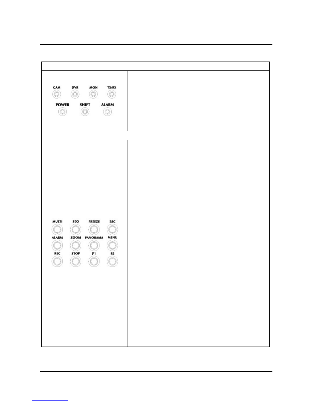
LEDs Part
CAM : The Camera status indication.
DVR : The DVR status Indication.
MON : The Monitor(Matrix switcher) status Indication.
TX/RX : Communication status indication.
POWER : Turned on while the power is supplied.
SHIFT : Turned on when SHIFT button is pressed.
ALARM : Turned on when an alarm is activated.
DVR Function Part
MUL TI : It is used to sele ct the Quad screen. Whenever this
button is pressed, the live screen status varies. In addition,
the user can operate the live screen to move to his/her
desired mode. A channel selection button is used to move
from the Quad screen to the full screen.
It is used to move to the Window mode and Full-Screen mode
during playback.
SEQ : It is used to move automatically from the live screen to
each channel in a sequential manner. In this case, Menu sets
the transition time for each channel.
FREEZE : It is used to bring the live screen to a temporary stop
in the full-screen mode or in the Quad mode.
ESC : It is used to escape from the OSD menu to an upper mode
or exit the present menu.
It is used to exit the Search mode.
It is used to exit the PTZ mode.
ALARM : This key will reset the alarm buzzer from the DVRs.
ZOOM : it is used to enlarge or reduce images.
PANORAMA : It is used to sequentially search screens per
frame in the Playback mode.
MENU : It is used to set DVR configurations.
REC : It allows for recording
STOP : It is used to exit the Playback mode.
F1/F2 : Function 1,2
13
Page 14
4. OPERATING CONTROLS
DVR Search Part
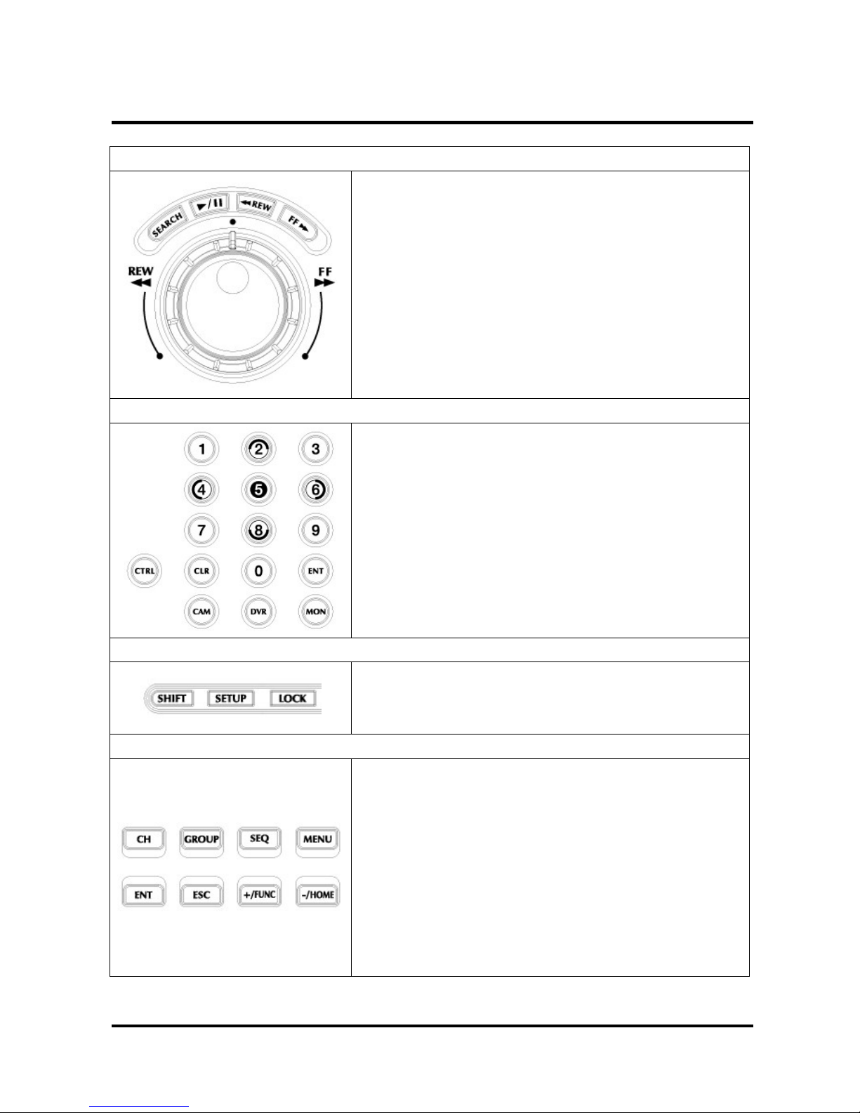
SEARCH : It is used to search the stored video data.
▶/ ll : It is used to activate the searched video data or bring
them to a temporary stop.
◀◀REW : It allows data to be wounded in the reverse
direction during retrieval.
FF▶▶ : It allows searched data to be played out at higher
speeds than the normal speed.
Jog : It is used to search by 1 Frame.
Shuttle : Same with REW,FF button
Miscellaneous Buttons Part
CTRL : Combination button for another function
Numeric : Select Camera ID, DVR ID or Monitor No.
CLR : Clear/Erase previous input.
ENT : It is used to select for set up Menu.
CAM : It is used to select the Camera No.
DVR : It is used to select the DVR No.
MON : It is used to select the Monitor No.
Controller Function Part
SHIFT : Combination button for another function
SETUP : It is used to setup the Controller’s configurations.
LOCK : It is used to lock all Controller functions.
Matrix Function Part
CH : It is used to select the channel.
GROUP : It is used for the Group function or Page Up in menu.
SEQ : It is used for the Sequence function or Page Down in
menu.
MENU : : It is used to set Matrix Switcher’s configurations.
ENT : It is used to save & exit or go to next menu
ESC : It is used to exit without saving in menu or go to previous
menu.
+/- : It is used to change values.
14
Page 15
4. OPERATING CONTROLS
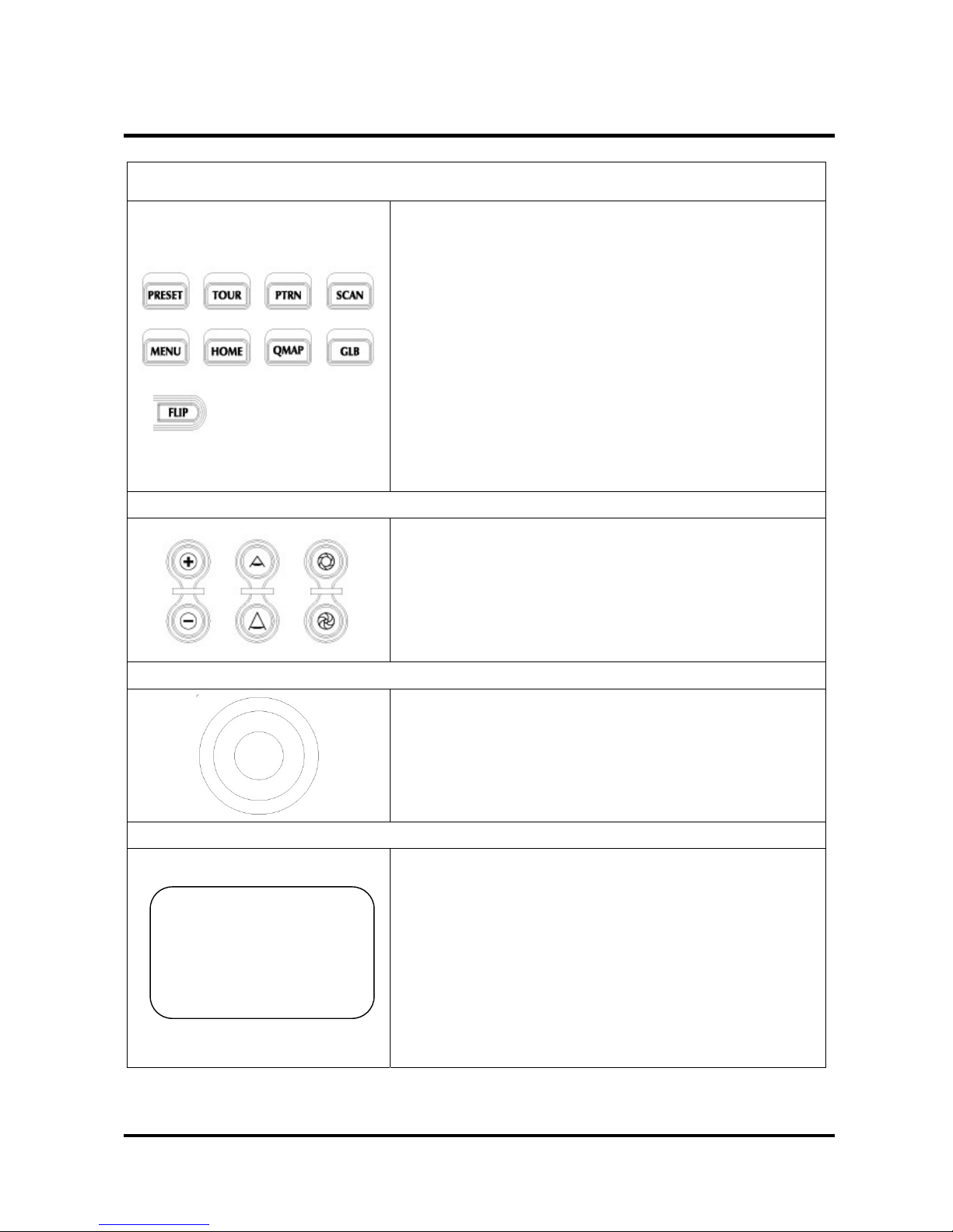
PTZ Camera Function Part
PRESET : It is used to set the Preset function.
TOUR : It is used to set the Tour function.
PTRN : It is used to set the Pattern function.
SCAN : It is used to set the Auto Scan function.
MENU : It is used to select the Set up Menu. It is also used to
execute or close Menu.
HOME : It is used to set the Home function.
QMAP : Quick Mapping function. It is used to call a User
Defined function.
GLB : It is used to call the Global function.
FILP : Rotate PAN by 180 degree.
ZOOM/FOCUS/IRIS Part
ZOOM In/Out : It is used to enlarge or reduce images by
adjusting the lens.
FOCUS Near/Far : It is used to adjust the Focus.
IRIS Open/Close : It is used to adjust the IRIS.
Joystick Part
User can pan/tilt cameras by moving Joy Stick up/down and
twist.
Once user enters Menu, Joy Stick can be used to scroll the
sub-menu.
LCD Part
① Indication of DVR ID
② Indication of CAM ID
15
③ Status Indication of INPUT
④ Indication of MON ID
⑤ Status Indication of PRST/TOUR/PTRN/SCAN/HOME
⑥ Indication of Protocol/Baud Rate
⑦ Status Indication of DVR
① DVR:001 ② CAM:0001
③ INPUT? : ④ MON:001
⑤ PRST:319 ⑥ CS-I:9600
⑦ DISPLAY
Page 16
5. OPERATION
5.1 Power
Turn on the controller power after all domes have initialized (wait at least 30 seconds)
1. Input 12VDC 1A to the Cyber controller & junction box
2. Connect Cyber controller and the junction box by RJ-45 Cable.
16
BOOTLOADER VXX DVR & DOME & MATRIX
H/W VER : VX.XX
38400 PO (ID:01) S/W VER : VX.XX
CONTROL UNIT
Confirm version
INPUT PASSWORD INPUT PASSWORD CURRENT STATUS
INPUT? : CORRECT PASSWORD MASTER MODE
Factory default password : 8888
CONFIG ENT : SKIP CURRENT STATUS
DVR:001 CAM:0001
MASTER : 1 SLAVE : 2 MASTER MODE
INPUT? : MON:001
PRST:319 CS-I:9600
* Press ENT : Return to the Latest Mode
DISPLAY
* Press 1 : Master Controller Mode
* Press 2 : Slave Controller Mode
5.2 DVR, Camera ID & Monitor NO. Selection
Input the ID number
and Press DVR or CAM or MON
* DVR ID : Input DVR ID number and Press DVR button.
* Camera ID : Input Camera ID number and Press CAM button.
* Monitor NO. : Input Monitor ID number and Press MON button.
DVR:001 CAM:0001 DVR:012 CAM:0002
INPUT? : MON:001 INPUT? : MON:005
PRST:319 CS-I:9600 PRST:319 CS-I:9600
DISPLAY DISPLAY
Page 17
5. OPERATION
* How to control On-Screen Menu Utility
Action Function
SETUP button Call the controller SETUP menu.
Joystick right Go into the sub-menu items or select current item.
Navigate the cursor up or down.
Joystick up/down
Go to previous or next item.
Up count/down count
Twist the Joystick
CLR,ESC button Exit without saving.
Go to previous menu.
ENT button Save & Exit
5.3 SYSTEM SETUP
Press SETUP button to setup the system of the controller. Below screen shows the controller setup
menu.
17
* Push the joystick to the up/down and
Push the joystick to the right.
5.3.1 SYSTEM INFO
The Cyber controller’s SETUP menu provides essential information about the Cyber controller.
When you see the screen, you can determine the controller type, software version.
SN : Serial Number
ID : Controller Address(ID)
H/W : Hardware Version
S/W : Software Version
SN : GXXXXXX
ID : 001
H/W : VX.XX
S/W : VX.XX
1. SYSTEM INFO
2. PASSWORD SETUP
3. BACKLIGHT TIME
4. FACTORY DEFAULT
5. SYSTEM RESET
6. CAMERA SETUP
7. DVR SETUP
Page 18
5. OPERATION
5.3.2 PASSWOR D SE TUP
When you want to change the password, you can change the password in password setup menu.
The unit requires the initial password before operation. The factory default password is 8888.
CURRENT PASSWORD
① Input the current password and Press ENT button.
INPUT? :
18
② Input the new password and Press ENT button.
NEW PASSWORD
INPUT? :
CONFIRM PASSWORD
③ Input the new password again and Press ENT button.
INPUT? :
Page 19
5. OPERATION
5.3.3 BACKLIGHT TIME SETUP
You may determine backlight turn-on time.
BACKLIGHT TIME: 011
While the Cyber controller is in idle mode,
(11~255 SECS)
The backlight will be turned off automatically
INPUT? :
after backlight time.
1: SAVE 2: EXIT
5.3.4 FACTORY DEFAULT
This all data is initialized.
DO YOU WA NT TO
Note : Be careful to select this mode since you can not
revert the current data forever.
INITIALIZE ALL DATA?
1: YES 2: NO
5.3.5 SYSTEM RESET
19
The controller restarts the system. But all saved data is not
initialized.
DO YOU WA NT TO
RESTART TH E SYST E M?
1: YES 2: NO
Page 20
5. OPERATION
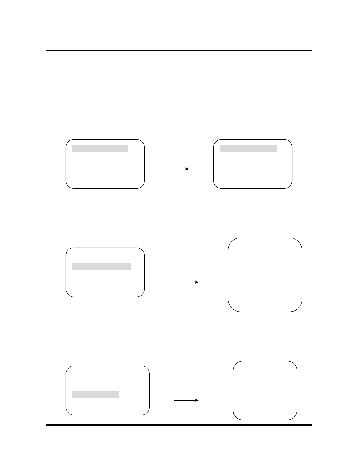
5.3.6 CAMERA SETUP
Set up Camera ID Range, the Protocol , Baud Rate of the Camera, and Output Port.
You can select Individual Setup or Whole Setup. Navigate the Cursor by pushing the joy stick up or
down. Cursor moves to the desired position.
○
1
CAM ID Setting: You can select the camera ID which you need to choose from CAM ID to CAM ID.
Input the Camera ID number
and Press ENT
20
Push the joystick right.
○
2
COMMUNICATION PROTOCOL Setting: In the Camera ID Range, You should choose the
Communication Protocol. To navigate and choose the communication protocol, push the joystick
left/right or twist the joy stick clockwise/counterclockwise.
Push the joystick left/right
or twist the joystick
clockwise/counterclockwise.
○
3
BAUD RATE Setting: In the Camera ID Range, You need to decide the Baud Rate.
To navigate and choose the Baud Rate, push the joystick left/right or twist the joy stick
clockwise/counterclockwise.
Push the joystick left/right
or twist the joystick
clockwise/counterclockwise.
Protocol
CYBER SCAN I
CYBER SCAN II
P-D TYPE
P-P TYPE
S-D DOME
BAUD RATE
2400 BPS
4800 BPS
9600 BPS
38400 BPS
→ CAM ID:[001 – 001] → CAM ID:[999 -– 999]
COMM.:CYBER SCAN I COMM.:CYBER SCAN I
BAUD :9600 BPS BAUD :9600 BPS
PORT :RS-485 PORT :RS-485
CAM ID:[999 – 999]
→COMM.:CYBER SCAN I
BAUD :9600 BPS
PORT :RS-485
CAM ID:[999 – 999]
COMM.:CYBER SCAN I
→BAUD :9600 BPS
PORT :RS-485
Page 21
5. OPERATION
○
4
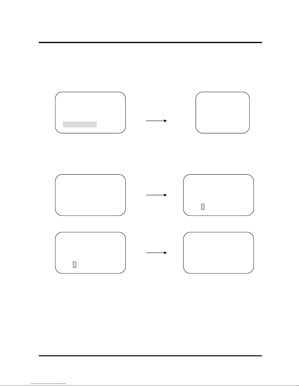
PORT Setting: In the Camera ID Range, You need to select the port. To navigate and choose the
Baud Rate, push the joystick left/right or twist the joy stick clockwise/counterclockwise. If you
set the controller to RS-232, controller sends the data through the RS-232 port. If you choose RS485/422, it sends the Communication protocol through the OUT port.
Push the joystick left/right
CAM ID:[999 – 999]
PORT
or twist the joystick
COMM.:CYBER SCAN I
RS-485
clockwise/counterclockwise.
BAUD :9600 BPS
RS-422
→PORT :RS-485
RS-232
⑤ STORE THE CAMERA SETUP
CAM ID:[999 – 999] DO YOU WANT TO
Press ENT
COMM.:CYBER SCAN I SA VE ALL DA TA?
BAUD :9600 BPS
1: SAVE 2: EXIT
→PORT :RS-485
21
Move the cursor to No.1
and Press ENT
DO YOU WANT TO
CHANGE COMPLETE..
SA VE ALL DA TA?
1: SAVE 2: EXIT
Page 22
5. OPERATION
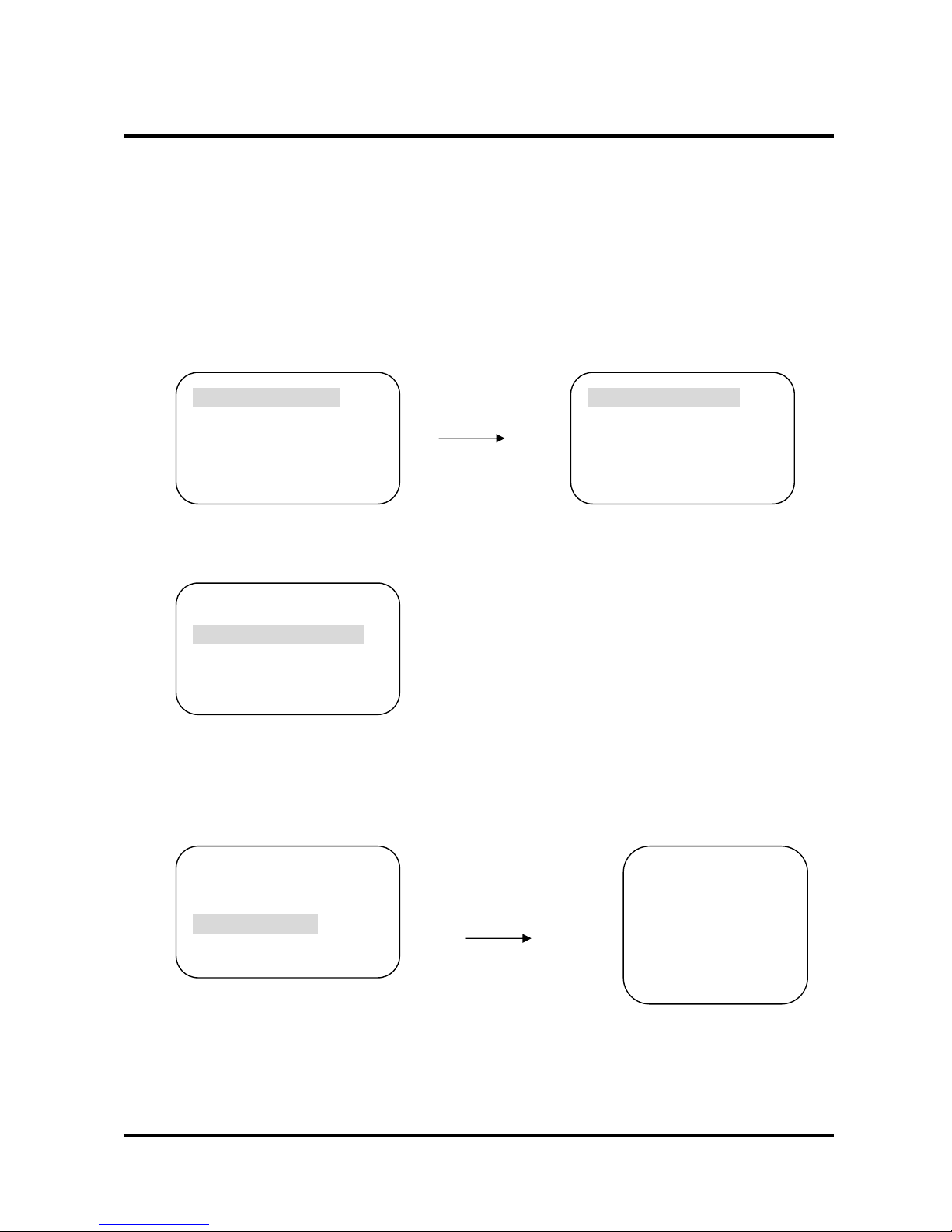
5.3.7 DVR SETUP
Set up DVR ID Range, the Protocol , Baud Rate of the DVR, and Output Port.
You can select Individual Setup or Whole Setup. Navigate the Cursor by pushing the joy stick up or
down. Cursor moves to the desired position.
○
1
DVR ID Setting : You can select the DVR ID which you want to set from DVR ID to DVR ID.
Input the Camera ID number
and Press ENT
22
→ DVR ID:[001 – 001] → DVR ID:[255 -– 255]
Push the joystick right.
COMM.:ENBEDDED DVR COMM.: ENBEDDED DVR
BAUD :9600 BPS BAUD :9600 BPS
PORT :RS-485 PORT :RS-485
○
2
COMMUNICATION PROTOCOL Setting : There is only Embedded DVR protocol.
DVR ID:[255 – 255]
→COMM.:EMBEDDED DVR
BAUD :9600 BPS
PORT :RS-485
○
3
BAUD RATE Setting : In the DVR ID Range, You need to decide the baud rate.
To navigate and choose the baud rate, push the joystick left/right or twist the joy stick
clockwise/counterclockwise.
Push the joystick left/right
DVR ID:[255 – 255]
BAUD RATE
or twist the joystick
COMM.:EMBEDDED DVR
2400 BPS
clockwise/counterclockwise.
→BAUD :9600 BPS
4800 BPS
PORT :RS-485
9600 BPS
38400 BPS
Page 23
5. OPERATION
○
4
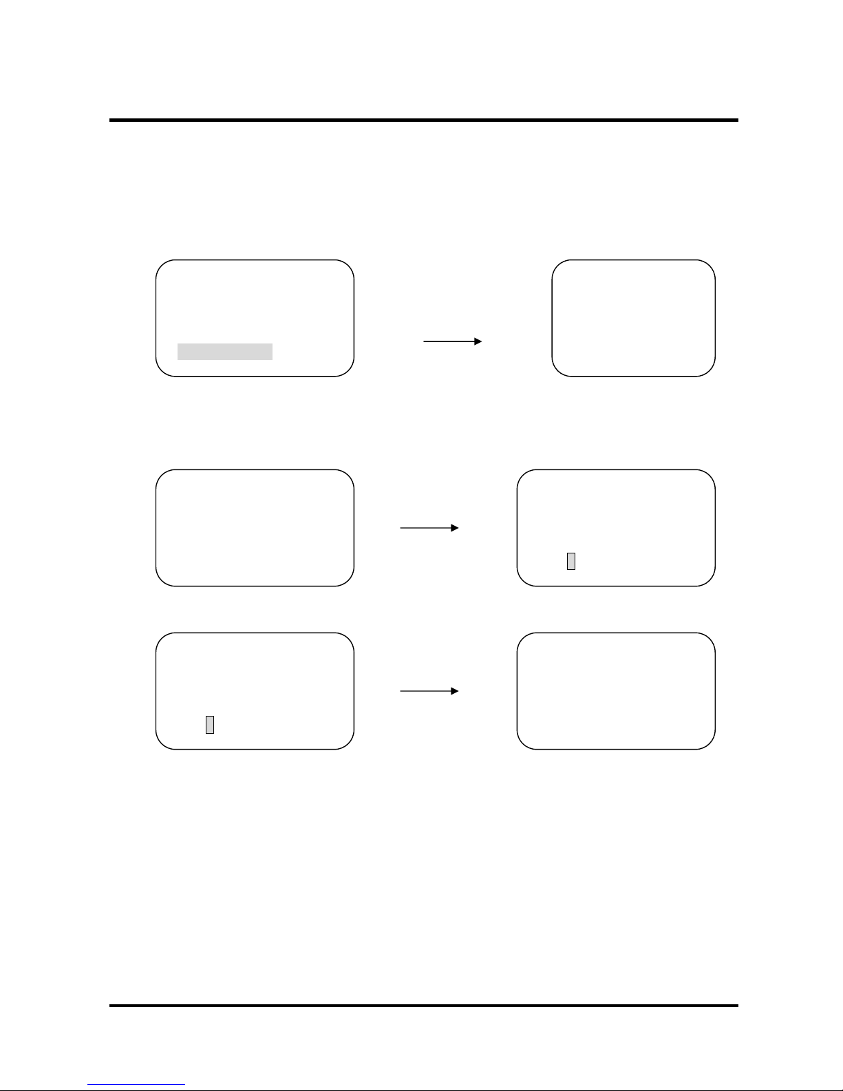
PORT Setting : In the DVR ID Range, You need to select the port. To navigate and choose the
Baud Rate, push the joystick left/right or twist the joy stick clockwise/counterclockwise. If you
set the controller to RS-232, controller sends the protocol through the RS-232 port. If you choose
RS-485/422, it sends the Communication protocol through the OUT port.
Push the joystick left/right
DVR ID:[255 – 255]
PORT
or twist the joy stick
COMM.:EMBEDDED DVR
RS-485
clockwise/counterclockwise.
BAUD :9600 BPS
RS-422
23
⑤ STORE THE DVR SETUP
Press ENT
Move the cursor to No.1
and Press ENT
RS-232
PORT :R→ S-485
DVR ID:[255 – 255] DO YOU WANT TO
COMM.:EMBEDDED DVR SAVE ALL DA TA?
BAUD :9600 BPS
1: SAVE 2: EXIT
→PORT :RS-485
DO YOU WANT TO
SA VE ALL DA TA?
1: SAVE 2: EXIT
CHANGE COMPLETE..
Page 24
5. OPERATION
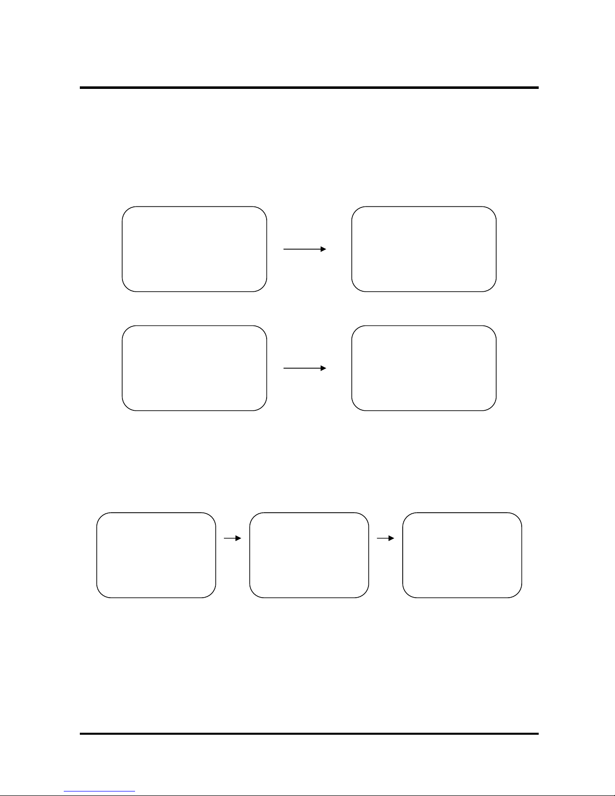
5.4 LOCK
If you don’t want another person (not authorized) to manipulate the controller, you can lock the
Cyber controller by pressing LOCK button.
5.4.1 Lock Setting
Input the current password and Press ENT
Press LOCK
DVR:001 CAM:0001 LOCK SETTING? :
INPUT?
INPUT? : MON:001
PRST:319 CS-I:9600
DISPLAY
LOCK SETTING? : LOCK MODE
INPUT?
CORRECT PASSWORD
5.4.2 Lock Cancel
Input the current password
and Press ENT
24
LOCK MODE
INPUT?
LOCK MODE
CORRECT PASSWORD
DVR:001 CAM:0001
INPUT: MON:001
PRST:319 CS-I:9600
DISPLAY
Page 25
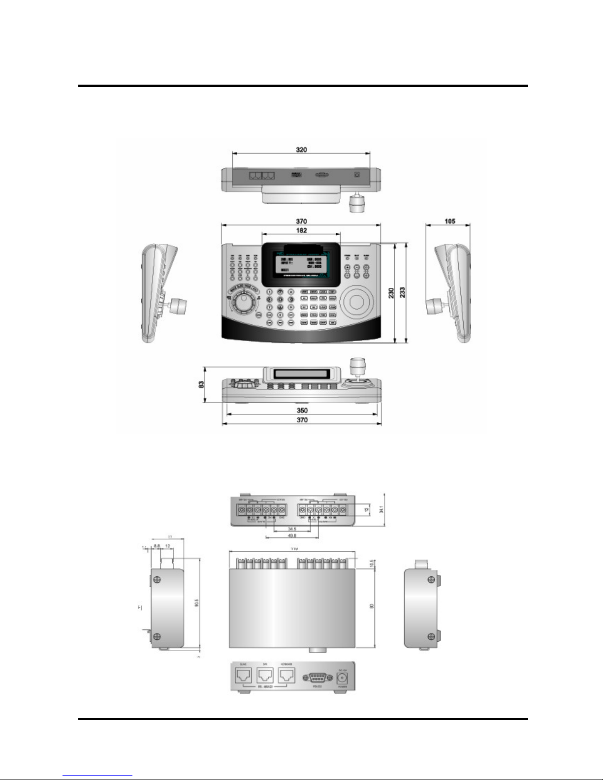
6. DIMENSION
A. Cyber Controller
B. Junction Box
25
Page 26
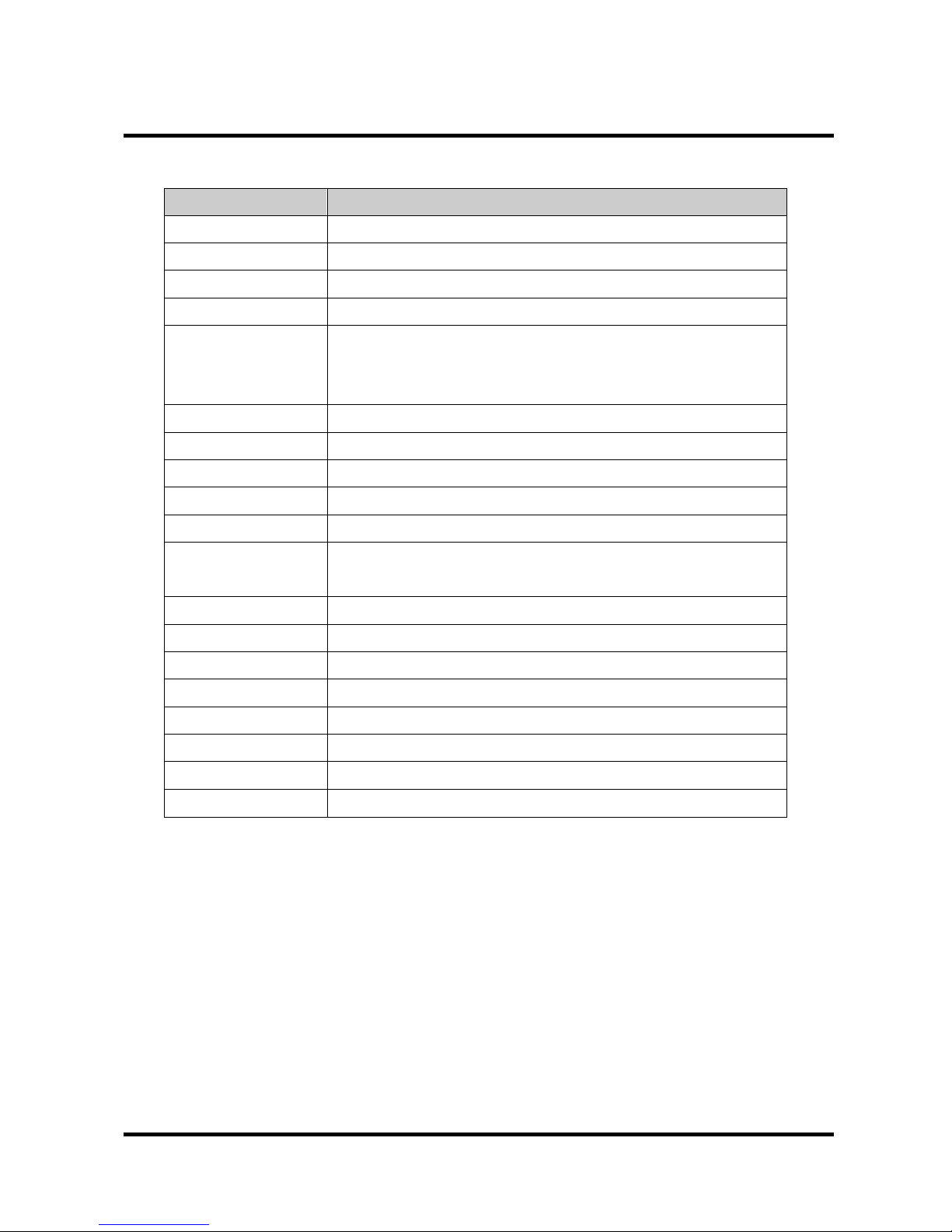
7.SPECIFICATION
Model Name Cyber Controller
Screen 4 Line LCD
Jog Shuttle Built-In
Controls 3X Axis Joy Stick Built In
Pan/Tilt Pan : Left/Right, Tilt : Up/Down
Key Features Zoom In/Out, Focus Near/Far, IRIS Open/Close,
DVR / Matrix /Cyber Scan Dome control,
Slave Controller Extendable
Multi-Protocol Cyber Scan (I,II) / P-D / P-P
Connection RJ-45 Connection via Junction Box or Ma trix/DVR
Communication RS-485 or RS-422
Communication Speed Baud Rate : 9600bps (OPT : 38400, 4800, 2400)
Operating Distance 1.2Km
PTZ/DVR/MON
Control No.
999 / 255 / 128
Power 12VDC 1A
Port RJ-45 X 2 (In, Out), RS-232 X 1
Material Plastic Cover
Finish Sanding and Spray
Temperature
0~50℃ (32~122℉)
Humidity 0~95% RH Non-condensing
Dimension 370(W) X 233(D) X 105(H)
Weight 1,500g
26
Page 27
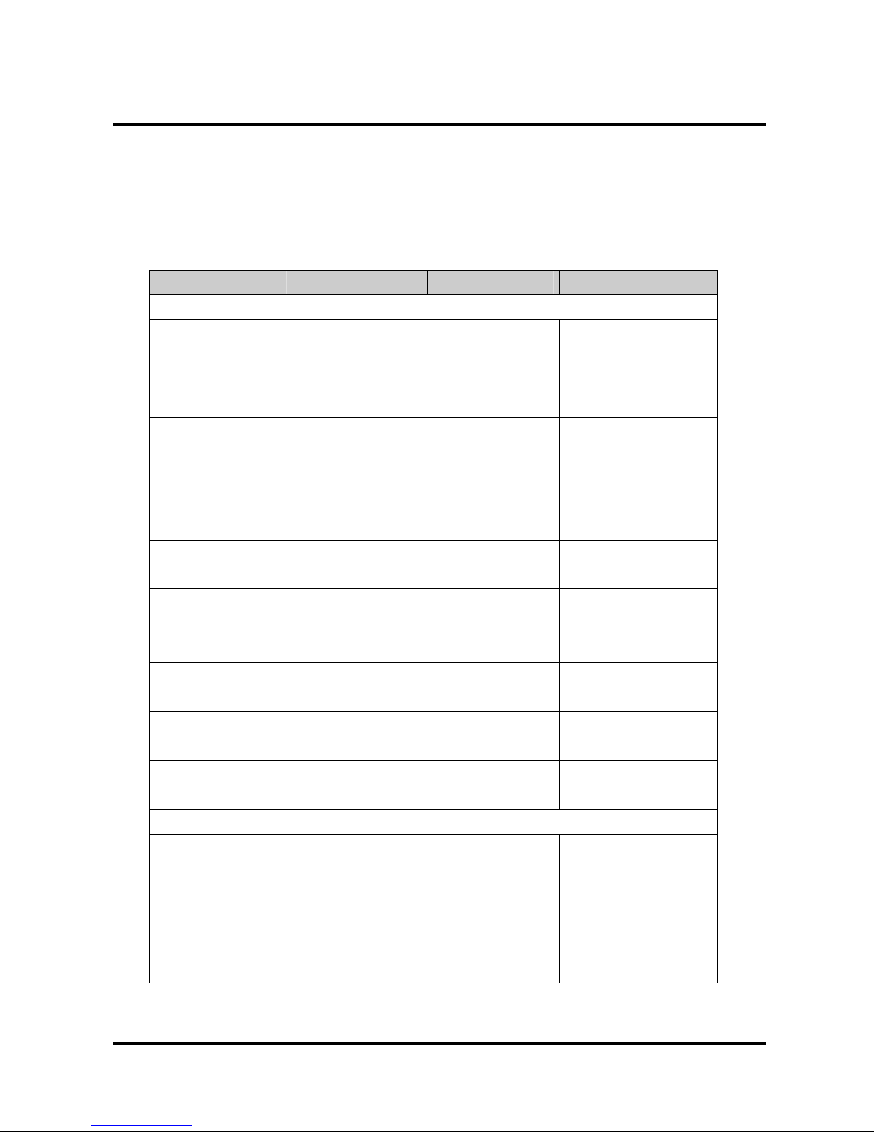
APPENDIX B - The List of GLB(Short) Key
If you use Cyber Scan dome camera and Cyber controller, you can use the following GLB short cut
key for the easy operations without accessing the main menu of the dome unit. (Cyber Scan protocol
only)
Note : Press GLB button, after press the numeric button. This function is available subject to
Global mode on, in the main menu.
GLB Key Function On/Off RMK
1. Camera Function
11 Privacy Zone Off
12 On
13 Over Tilt Off
14 On
20 Day/Night Auto
21 Off
22 On
23 Digital Zoom Off
24 On
25 Back Light Off
26 On
27 WB ATW
28 (White Balance) Indoor
29 Outdoor
31 Flicker less Off
32 On
33 Auto Focus Auto
34 Manual
35 BMB Mode Off
36 On
2. Display Functions (OSD)
71 All Display Off
72 On
73 Zoom Magnitude On/Off Toggle
74 Dome ID On/Off Toggle
75 Dome Mode On/Off Toggle
76 Pan/Tilt Angle On/Off Toggle
27
Page 28
APPENDIX B - The List of GLB(Short) Key
77 Area Title On/Off Toggle
78 Operation Title On/Off Toggle
79 Flag Display On/Off Toggle
80 Time Display On/Off Toggle
3. Dome Operations Functions
81 Flip Off
82 On
83 Mirror/Reverse Off
84 Flip
28
Page 29
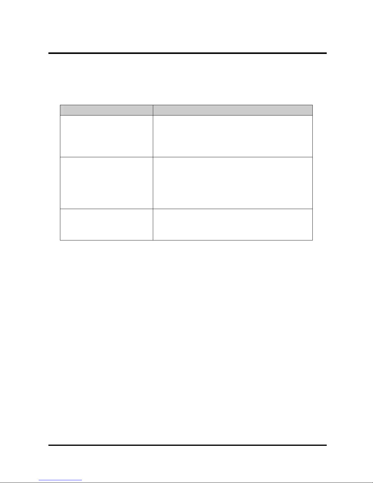
APPENDIX B - Trouble Shooting
If problems occur, verify the installation of the camera with the instructions in this manual and with
other operating equipment. Isolate the problem to the specific pieces of equipment in the system and
refer to the equipment manual for further in formation.
Problem Possible Solution
a. Press 5 button then DVR button when you forget
the password once the controller is turned off then
on. The controller will be initialized to Default
Password, 8888.
If you forget the password
a. Please check the ID, Protocol, Baud Rate and
Address of the camera and then clarify of them in
the controller.
If the camera is not working
b. Please check the wiring connection between the
controller and the junction box.
a. Please check the main power and power If the controller is not
working consumption of the controller unit.
b. Please check if the controller is in the lock mode.
29
Page 30
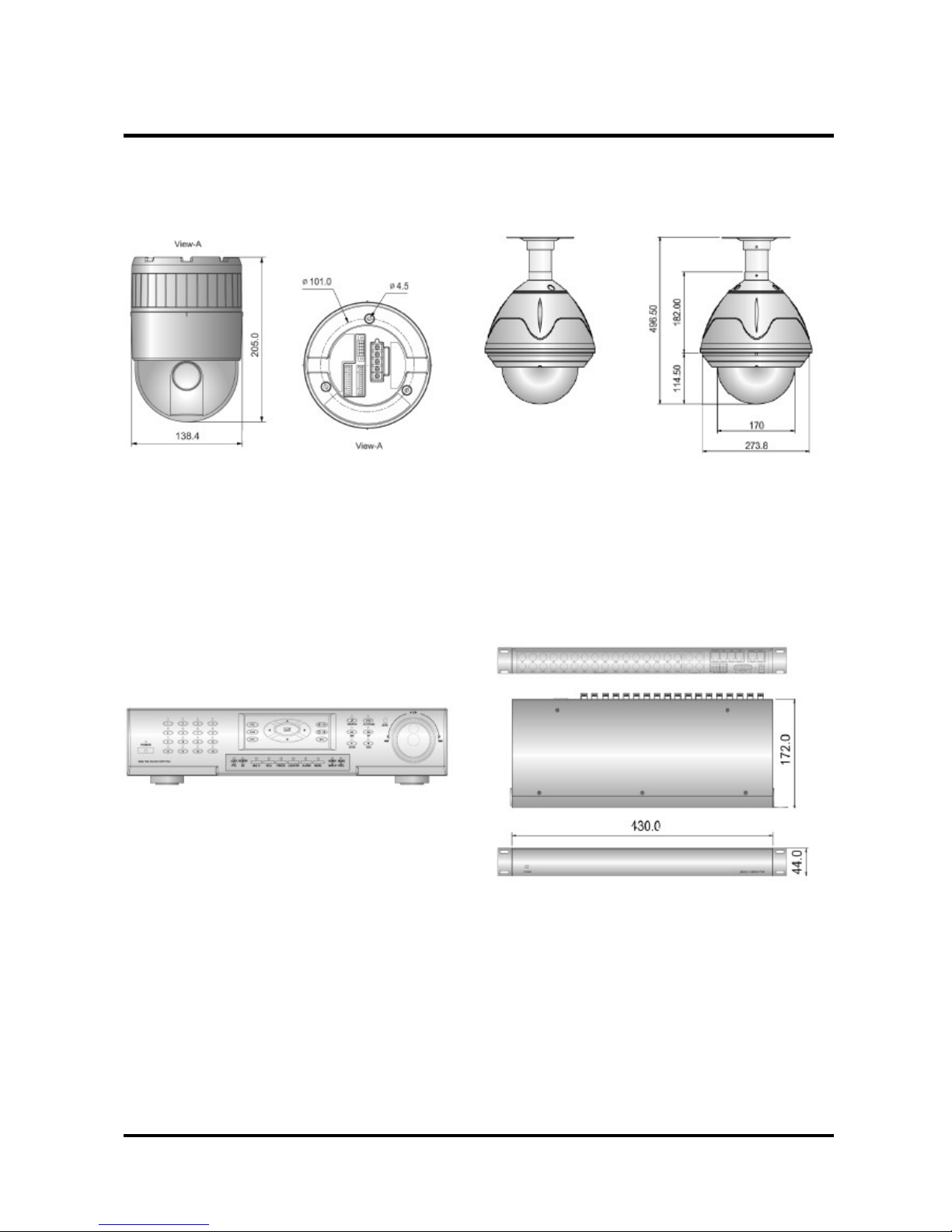
APPENDIX C-OPTIONAL ITEM
A. Cyber Scan Dome Camera B. Cyber Scan Pre-Pack Dome Camera
C. Digital Video Recorder D. Video Matrix System
30
Page 31

MEMO
31
 Loading...