

Page 1

CYAN
Z-Series
Engineering and Planning Guide
Release 5.0 Cyan, Inc. 2013
Page 2

Cyan Z-Series Engineering and Planning Guide Release 5.0
Copyright and Trademark
Copyright © 2009 – 2013 Cyan, Inc. All Rights Reserved. All text, images, graphics, animation, videos,
music and other materials in this publication are subject to the copyright and other intellectual property
rights of Cyan, Inc. or its licensors. These materials may not be reproduced, transmitted, distributed,
modified or posted to other websites or printed without the express written permission of Cyan, Inc.
Cyan®, the Cyan logo, Z22™, Z33®, Z77®, Blue Planet™ and other trademarks and service marks of Cyan
appearing in this publication are the property of Cyan. Trade names, trademarks and service marks of other
companies appearing in this publication are the property of the respective holders.
Page 2 © 2013 Cyan, Inc. – All Rights Reserved. 700-0023-05-00 Rev. 1
Page 3

Cyan Z-Series Engineering and Planning Guide Release 5.0
Naming Conventions
Throughout this guide, a standardized system is used to identify various functions or to stress importance to
the reader.
Important! — Information that must be seriously considered.
Note: Special suggestions, advice, or information that should be seriously considered.
700-0023-05-00 Rev. 1 © 2013 Cyan, Inc. – All Rights Reserved. Page 3
Page 4
Cyan Z-Series Engineering and Planning Guide Release 5.0
Before you work on any equipment, be aware of the hazards involved with electrical circuitry
SAVE THESE INSTRUCTIONS
a moderate level of awareness. There is a moderate level of danger to
Before you work on any equipment, be aware of the hazards involved with electrical circuitry
rings, necklaces, bracelets, key chains, metal wristwatches, and apparel with metal buttons).
1 and AS/NZS 3260) should be
be accessed only through the use of a special tool, lock and key, or other means of security.
A copy of the installation documents and the list of accessories can be found in CyLibrary in
Safety Symbols and Labels
Read and understand all warning labels before working with equipment.
Warning
IMPORTANT SAFETY INSTRUCTIONS
This warning symbol means danger. You are in a situation that could cause bodily injury.
Caution
and be familiar with standard practices for preventing accidents.
Environment requires
yourself or others.
Laser Equipment Present
Electrostatic Discharge (ESD) Sensitive Equipment
Safety and Compliance Information
Warning
IMPORTANT SAFETY INSTRUCTIONS
This warning symbol means danger. You are in a situation that could cause bodily injury.
Warning
Warning
Warning Installation of the equipment must comply with local and national electrical codes.
Warning
Warning
and be familiar with standard practices for preventing accidents.
SAVE THESE INSTRUCTIONS
Before working on the equipment, remove conductive clothing and jewelry (for example:
Conductive items can cause serious burns or weld the metal object to the terminals.
Only trained and qualified personnel (as defined in IEC 60950allowed to install, replace, or service this equipment.
This unit is intended for installation in restricted access areas. A restricted access area can
Read the installation directions before connecting the system to the power source or
installing the modules and the accessories which are intended to be used only with Cyan
Optical Packet system.
Cyan Central at http://cyaninc.com/resources/compliance.
Page 4 © 2013 Cyan, Inc. – All Rights Reserved. 700-0023-05-00 Rev. 1
Page 5

Cyan Z-Series Engineering and Planning Guide Release 5.0
Do not perform cabling on an electrically live system. Before performing any of the following
protection to be provided as part of the facility. Install only
shelf assembly. Failure to ensure rack stability may cause the rack to tip over.
Never use the cable management guide to lift the chassis. This is NOT the intended purpose
Ensure that all power wiring is sufficient for the load carried to the shelf assembly. All wiring
and installation must be in accordance with local building and electrical codes acceptable to
an electrician if you are uncertain that suitable grounding is
integral circuit protection.
Warning
Warning A readily accessible two-poled disconnect device must be incorporated in the fixed wiring.
Warning
Warning
Warning
Warning
Warning
Warning
Warning
procedures, ensure that power is removed from the DC circuit.
No user serviceable parts are contained inside. Contact the manufacturer regarding service
of this equipment.
This device requires short-circuit
in accordance with national and local wiring regulations.
The copper RJ-45 SFP modules are suitable for connection only to shielded Ethernet
intra-building cabling grounded at both ends.
Do not work on the system, or connect or disconnect cables during periods of lightning
activity.
Do not stack the chassis on any other equipment. If the chassis falls, it can cause severe
bodily injury and equipment damage.
Stability hazard. The rack must be stabilized or bolted to the floor before you mount this
To prevent bodily harm when mounting or servicing this device in a rack, you must ensure
that the shelf remains stable. The Following guidelines are provided to ensure your safety:
• This unit should be mounted at the bottom of the rack if it is the only unit in the rack.
• When mounting this unit in a partially filled rack, load the rack from bottom to the
top with the heaviest component at the bottom of the rack.
• If the rack is provided with stabilizing devices, install the stabilizers before
mounting or servicing the unit in the rack.
Warning
of the cable guide. Personal injury and/or damage to the Z22 shelf assembly may result.
Warning
Warning
the authorities in the countries where the equipment is installed and used.
This equipment must be grounded. Never defeat the ground conductor or operate the
equipment in the absence of a suitably installed ground conductor. Contact the appropriate
electrical inspection authority or
Warning
Warning
Warning
available.
When installing or replacing the unit, the ground connection must always be made first and
disconnected last.
This unit might have more than one power supply connection. All connections must be
removed to de-energize the unit.
For connections outside the building where the equipment is installed, the 10/100/1000
Ethernet ports must be connected through an approved network termination unit with
Warning
Operating this equipment in an area that exceeds ambient air temperature of 50° C / 120° F
will result in overheating.
700-0023-05-00 Rev. 1 © 2013 Cyan, Inc. – All Rights Reserved. Page 5
Page 6

Cyan Z-Series Engineering and Planning Guide Release 5.0
regulations.
the Hungarian EMC Class A requirements (MSZEN55022). Class A equipment is designed for
irements for industrial use. The seller
or buyer should be aware of this. If this type was sold or purchased by mistake, it should be
Environment requires a moderate level of awareness. There is a moderate level of danger to
Warning
Warning
Warning
Warning
Warning
Warning
Warning
Warning
Operating I-Temp equipment in an area that exceeds ambient air temperature of 65° C /
149° F will result in overheating.
Ultimate disposal of this product should be handled according to all national laws and
Connect the unit only to DC power source that complies with the safety extra-low voltage
(SELV) requirements in IEC 60950-based safety standards.
This is a Class A product. In a domestic environment this product may cause radio
interference, in which case the user may be required to take adequate measures.
This is a Class A product based on the standard of the VCCI Council. If this equipment is
used in a domestic environment, radio interference may occur, in which case, the user may
be required to take corrective actions.
This equipment is a class A product and should be used and installed properly according to
typical commercial establishments for which special conditions of installation and
protection distance are used.
This is a Class A Information Product. When used in residential environment, it may cause
radio frequency interference, under such circumstances, the user may be requested to take
appropriate countermeasures.
This is a Class A Device and is registered for EMC requ
Warning
replaced with a residential-use type.
Air Management Boards are required to meet EMI certification standards. Air Management
Boards must be installed to cover all unused slots.
Caution
yourself or others.
Caution
Caution Keep all ventilation openings clear and unobstructed.
Caution To prevent damage, do NOT install or remove XFP/SFP transceivers with cables attached.
Caution
To avoid damage to the Z22 shelf, the fan module should not be removed for longer than 60
seconds from an operating system.
The Air Management Boards are essential to proper cooling of the shelf assembly. Air
Management Boards must be installed over all unused slot openings to prevent damage
Caution
from overheating.
Do not apply power to the unit until you complete all installation steps and check the
continuity of the battery and battery return. When terminating power, return, and frame
ground, do not use soldering lug connectors, push-in connectors, quick-connect
Caution Star washers must be used for anti-rotation on all power and ground fasteners.
Caution Use copper conductors only.
connectors, or other friction-fit connectors.
Page 6 © 2013 Cyan, Inc. – All Rights Reserved. 700-0023-05-00 Rev. 1
Page 7
Cyan Z-Series Engineering and Planning Guide Release 5.0
OSP environment, the appropriate hardened modules must be used and DC power interfaces
Some Cyan shelf components are Electrostatic Discharge (ESD) sensitive devices. Conform
area is likely to cause harmful interference, in which case, the user will be required to correct
Caution
Caution
Caution
Caution
Caution
Caution
Note
This equipment is suitable for installation in Network Telecommunications Facilities,
Customer Premises, and OSPs. If this equipment is installed in a Customer Premise or an
must be connected to DC power via a proper fuse panel.
The intra-building port(s) of the equipment or sub-assembly is suitable for connection to
intra building or unexposed wiring or cabling only. The intra-building port(s) of the
equipment or sub-assembly MUST NOT be metallically connected to interfaces that connect
to the Outside Plant (OSP) or its wiring. These interfaces are designed for use as
intra-building interfaces only (Type 2 or Type 4 ports as described in GR-1089-CORE, Issue
4) and require isolation from the exposed OSP cabling. The addition of Primary Protectors is
not sufficient protection in order to connect these interfaces metallically to OSP wiring.
This equipment is intended to be grounded to a Common Bonding Network per GR-CORE
1089. Ensure that the host is connected to earth ground during normal use.
Hazard Level 1M Laser radiation. Do not view directly with non-attenuating optical
instruments.
This product may employ Class 1M SFP or XFP. Check pluggable transceiver label for laser
classification.
to the following rules:
• Observe standard precautions for handling ESD-sensitive devices.
• Assume that all solid-state electronic devices are ESD-sensitive.
• Ensure that you are grounded with a grounded wrist strap or equivalent while
working with ESD-sensitive devices.
• Transport, store, and handle ESD-sensitive devices in static-safe environments.
This equipment has been tested and found to comply with the limits for a Class A digital
device, pursuant to Part 15 of the FCC Rules. These limits are designed to provide
reasonable protection against harmful interference when the equipment is operated in a
commercial environment. This equipment generates, uses, and can radiate radio frequency
energy and, if not installed and used in accordance with the instruction manual, may cause
harmful interference to radio communications. Operation of this equipment in a residential
Note
the interference at own expense.
The battery return connection is treated as DC-isolated (DC-I), as defined in Telcordia
GR-1089-CORE Issue 3.
Note This Class A digital apparatus complies with Canadian ICES-003.
700-0023-05-00 Rev. 1 © 2013 Cyan, Inc. – All Rights Reserved. Page 7
Page 8

Cyan Z-Series Engineering and Planning Guide Release 5.0
Page 8 © 2013 Cyan, Inc. – All Rights Reserved. 700-0023-05-00 Rev. 1
Page 9

Contents
Safety Symbols and Labels ......................................................................................................................... 4
Safety and Compliance Information .......................................................................................................... 4
New in this Release .................................................................................................................................... 21
Chapter 1: Cyan Z-Series Shelves ........................................................................................................ 23
1.1 Cyan Z22 Shelf............................................................................................................................... 23
1.1.1 Z22 Shelf Description .............................................................................................................. 24
1.1.2 Z22 Card Installation Guidelines ............................................................................................. 25
1.1.3 CEMi Controller Card: +24 Volt ............................................................................................. 26
1.1.4 Z22 Physical ............................................................................................................................ 26
1.1.5 Z22 External Timing ................................................................................................................ 27
1.1.6 Z22 Alarms .............................................................................................................................. 27
1.1.7 Z22 Shelf Power ...................................................................................................................... 28
1.2 Cyan Z33 Shelf............................................................................................................................... 29
1.2.1 Z33 Shelf Description .............................................................................................................. 31
1.2.2 Z33 Line Card Configuration Guidelines ................................................................................ 32
1.2.3 Common Equipment Module (CEMi) ..................................................................................... 33
1.2.4 Z33 Timing .............................................................................................................................. 35
1.2.5 Z33 Alarms .............................................................................................................................. 36
1.2.6 Z33 Shelf Power ...................................................................................................................... 36
1.2.7 Z33 Physical ............................................................................................................................ 37
1.3 Cyan Z77 Shelf v2 .......................................................................................................................... 37
1.3.1 Z77 Card Installation Guidelines ............................................................................................. 40
1.3.2 Z77 Power ................................................................................................................................ 41
1.3.3 Z77 Physical ............................................................................................................................ 41
1.3.4 Z77 Timing .............................................................................................................................. 41
700-0023-05-00 Rev. 1 © 2013 Cyan, Inc. – All Rights Reserved. Page 9
Page 10

Cyan Z-Series Engineering and Planning Guide Release 5.0
1.3.5 Z77 Management ..................................................................................................................... 41
1.4 Cyan L-AMP Shelf ......................................................................................................................... 42
1.4.1 L-AMP Shelf Pinouts .............................................................................................................. 43
1.4.2 L-AMP Interfaces .................................................................................................................... 44
1.4.3 L-AMP OSC Specifications..................................................................................................... 45
1.4.4 L-AMP Features ...................................................................................................................... 45
1.4.5 L-AMP Applications ............................................................................................................... 45
1.4.6 L-AMP Physical ...................................................................................................................... 45
1.4.7 L-AMP Power .......................................................................................................................... 46
1.4.8 L-AMP Compliance ................................................................................................................. 46
Chapter 2: Z-Series Line Cards, Modules, Optics, and Optical Protection ..................................... 47
2.1 LAD Modules ................................................................................................................................. 49
2.1.1 Functional Interfaces................................................................................................................ 56
2.1.2 LAD OSC Specifications ......................................................................................................... 57
2.1.3 Management ............................................................................................................................ 57
2.1.4 Physical .................................................................................................................................... 57
2.1.5 Power ....................................................................................................................................... 58
2.1.6 Environmental .......................................................................................................................... 58
2.1.7 LAD Module Wavelength Assignments .................................................................................. 58
2.1.8 LAD-2P and LAD-8i 1310nm Add/Drop Port ........................................................................ 60
2.1.9 LAD-2G 1550nm Add/Drop Port ............................................................................................ 60
2.1.10 Compliance / Safety ................................................................................................................. 60
2.2 DTM-8 and DTM-8G Transponder Modules ................................................................................. 61
2.2.1 DTM-8/DTM-8G System Requirements ................................................................................. 64
2.2.2 Applications ............................................................................................................................. 64
2.2.3 DTM-8
Interfaces .................................................................................................................... 64
2.2.4 DTM-8G Interfaces ................................................................................................................. 64
2.2.5 DTM-8/DTM-8G Management ............................................................................................... 65
2.2.6 DTM-8/DTM-8G Physical ...................................................................................................... 65
2.2.7 DTM-8/DTM-8G Power .......................................................................................................... 65
2.2.8 DTM-8/DTM-8G Environmental ............................................................................................ 65
2.2.9 DTM-8/DTM-8G Compliance / Safety ................................................................................... 65
2.3 2.5G-LME4 Multiplex-Transponder Module ................................................................................. 66
2.3.1 System Requirements .............................................................................................................. 67
2.3.2 Interfaces .................................................................................................................................. 67
Page 10 © 2013 Cyan, Inc. – All Rights Reserved. 700-0023-05-00 Rev. 1
Page 11

Cyan Z-Series Engineering and Planning Guide Release 5.0
2.3.3 Management ............................................................................................................................ 68
2.3.4 Physical .................................................................................................................................... 68
2.3.5 Power ....................................................................................................................................... 68
2.3.6 Environmental .......................................................................................................................... 68
2.3.7 Compliance / Safety ................................................................................................................. 68
2.4 PME-412 Packet Multiplexer Module ........................................................................................... 69
2.4.1 Synchronous Ethernet .............................................................................................................. 71
2.4.2 System Requirements .............................................................................................................. 71
2.4.3 PME-412 Ethernet Services, OAM, QoS, and Synchronization .............................................. 71
2.4.4 PME-412 Capacity ................................................................................................................... 72
2.4.5 Optical Transport ..................................................................................................................... 73
2.4.6 Interfaces .................................................................................................................................. 73
2.4.7 Management ............................................................................................................................ 73
2.4.8 Physical .................................................................................................................................... 73
2.4.9 Power ....................................................................................................................................... 74
2.4.10 Environmental .......................................................................................................................... 74
2.4.11 Standards.................................................................................................................................. 74
2.4.12 Compliance / Safety ................................................................................................................. 74
2.5 PME-216i Packet Multiplexer Module .......................................................................................... 75
2.5.1 Synchronous Ethernet .............................................................................................................. 78
2.5.2 System Requirements .............................................................................................................. 78
2.5.3 PME-216i Ethernet Services, OAM, QoS, and Synchronization ............................................ 78
2.5.4 PME-216i Capacity ................................................................................................................. 79
2.5.5 Standards.................................................................................................................................. 80
2.5.6 Optical Transport ..................................................................................................................... 80
2.5.7 Interfaces .................................................................................................................................. 80
2.5.8 Manag
ement ............................................................................................................................ 81
2.5.9 Physical .................................................................................................................................... 81
2.5.10 Power ....................................................................................................................................... 81
2.5.11 Environmental .......................................................................................................................... 81
2.5.12 Compliance / Safety ................................................................................................................. 81
2.6 PSW-10G10 Packet Module .......................................................................................................... 82
2.6.1 System Requirements .............................................................................................................. 85
2.6.2 Ethernet Services and Standards .............................................................................................. 85
2.6.3 Optical Transport ..................................................................................................................... 85
700-0023-05-00 Rev. 1 © 2013 Cyan, Inc. – All Rights Reserved. Page 11
Page 12

Cyan Z-Series Engineering and Planning Guide Release 5.0
2.6.4 Interfaces .................................................................................................................................. 85
2.6.5 Management ............................................................................................................................ 85
2.6.6 Physical .................................................................................................................................... 85
2.6.7 Power ....................................................................................................................................... 86
2.6.8 Environmental .......................................................................................................................... 86
2.6.9 Compliance / Safety ................................................................................................................. 86
2.7 PSW-618 Packet Module ............................................................................................................... 87
2.7.1 System Requirements .............................................................................................................. 89
2.7.2 Ethernet Services and Standards .............................................................................................. 89
2.7.3 Optical Transport ..................................................................................................................... 89
2.7.4 Interfaces .................................................................................................................................. 89
2.7.5 Management ............................................................................................................................ 89
2.7.6 Physical .................................................................................................................................... 90
2.7.7 Power ....................................................................................................................................... 90
2.7.8 Environmental .......................................................................................................................... 90
2.7.9 Compliance / Safety ................................................................................................................. 90
2.8 TSW-10G10 Packet Aggregation and Transport Module .............................................................. 91
2.8.1 System Requirements .............................................................................................................. 92
2.8.2 Interfaces and Optical Transport .............................................................................................. 92
2.8.3 Management ............................................................................................................................ 93
2.8.4 Physical .................................................................................................................................... 93
2.8.5 Power ....................................................................................................................................... 93
2.8.6 Environmental .......................................................................................................................... 93
2.8.7 Compliance / Safety ................................................................................................................. 93
2.9 LAC-8 Lambda Aggregator Module .............................................................................................. 94
2.9.1 System Requirements .............................................................................................................. 94
2.9.2 Functional Interfaces................................................................................................................ 94
2.9.3 Manag
ement ............................................................................................................................ 95
2.9.4 Physical .................................................................................................................................... 95
2.9.5 Power ....................................................................................................................................... 95
2.9.6 Environmental .......................................................................................................................... 95
2.9.7 LAC-8 Wavelength Assignments ............................................................................................ 95
2.9.8 Compliance / Safety ................................................................................................................. 96
Page 12 © 2013 Cyan, Inc. – All Rights Reserved. 700-0023-05-00 Rev. 1
Page 13

Cyan Z-Series Engineering and Planning Guide Release 5.0
2.10 LAC-4P Lambda Aggregator CWDM Terminal Multiplexer ........................................................ 97
2.11 SFT-8 Module Transponder Module .............................................................................................. 98
2.11.1 System Requirements ............................................................................................................ 100
2.11.2 Functional Interfaces.............................................................................................................. 100
2.11.3 Management .......................................................................................................................... 100
2.11.4 Physical .................................................................................................................................. 100
2.11.5 Power ..................................................................................................................................... 100
2.11.6 Environmental ........................................................................................................................ 101
2.11.7 Compliance / Safety ............................................................................................................... 101
2.12 SFT-10G16 Multi-Rate Transponder Module .............................................................................. 102
2.12.1 SFT-10G16 Applications ....................................................................................................... 104
2.12.2 System Requirements ............................................................................................................ 104
2.12.3 Management .......................................................................................................................... 104
2.12.4 Physical .................................................................................................................................. 104
2.12.5 Power ..................................................................................................................................... 104
2.12.6 Environmental ........................................................................................................................ 104
2.12.7 Compliance / Safety ............................................................................................................... 104
2.13 DTM-100G Transponder Module ................................................................................................ 105
2.13.1 System Requirements ............................................................................................................ 107
2.13.2 DTM-100G Applications ....................................................................................................... 107
2.13.3 Interfaces ................................................................................................................................ 107
2.13.4 Optical Transport ................................................................................................................... 108
2.13.5 Management .......................................................................................................................... 108
2.13.6 Physical .................................................................................................................................. 108
2.13.7 Power ..................................................................................................................................... 108
2.13.8 Environmental ........................................................................................................................ 108
2.13.9 Co
mpliance / Safety ............................................................................................................... 109
2.14 MSE-1482 Multiservice SONET/SDH Aggregation/ Transport .................................................. 110
2.14.1 Applications ........................................................................................................................... 114
2.14.2 System Requirements ............................................................................................................ 114
2.14.3 Functional Interfaces.............................................................................................................. 114
2.14.4 GbE Support .......................................................................................................................... 114
2.14.5 Timing / Synchronization ...................................................................................................... 114
2.14.6 Management .......................................................................................................................... 114
2.14.7 Physical .................................................................................................................................. 115
700-0023-05-00 Rev. 1 © 2013 Cyan, Inc. – All Rights Reserved. Page 13
Page 14

Cyan Z-Series Engineering and Planning Guide Release 5.0
2.14.8 Power ..................................................................................................................................... 115
2.14.9 Environmental ........................................................................................................................ 115
2.14.10 Compliance / Safety ........................................................................................................... 115
2.15 FLX-216i Multi-Rate OTN Muxponder Module ......................................................................... 116
2.15.1 System Requirements ............................................................................................................ 117
2.15.2 Applications ........................................................................................................................... 118
2.15.3 Interfaces ................................................................................................................................ 118
2.15.4 OTN Multiplexing and Cross-Connect Formats .................................................................... 118
2.15.5 Optical Transport ................................................................................................................... 118
2.15.6 Management .......................................................................................................................... 118
2.15.7 Physical .................................................................................................................................. 118
2.15.8 Power ..................................................................................................................................... 118
2.15.9 Environmental ........................................................................................................................ 119
2.15.10 Compliance / Safety ........................................................................................................... 119
2.16 WSS-402 and WSS-404 Wavelength Selective Switch ............................................................... 120
2.16.1 WSS DWDM Specifications ................................................................................................. 126
2.16.2 WSS OSC Specifications ....................................................................................................... 127
2.16.3 System Requirements ............................................................................................................ 127
2.16.4 Physical .................................................................................................................................. 127
2.16.5 Power ..................................................................................................................................... 127
2.16.6 Environmental ........................................................................................................................ 127
2.16.7 WSS/AWG-40 Wavelength Assignments ............................................................................. 128
2.16.8 Compliance / Safety ............................................................................................................... 128
2.17 Broadband Operating System Supervisor .................................................................................... 129
2.17.1 Shelf Compatibility ................................................................................................................ 130
2.17.2 CPU........................................................................................................................................ 130
2.17.3 RAM
...................................................................................................................................... 130
2.17.4 Timing.................................................................................................................................... 130
2.17.5 Craft ....................................................................................................................................... 130
2.17.6 Physical .................................................................................................................................. 130
2.17.7 Power ..................................................................................................................................... 130
2.17.8 Compliance ............................................................................................................................ 130
2.17.9 Electrical ................................................................................................................................ 131
2.18 BOSS Termination Module .......................................................................................................... 131
2.18.1 Shelf Compatibility ................................................................................................................ 133
Page 14 © 2013 Cyan, Inc. – All Rights Reserved. 700-0023-05-00 Rev. 1
Page 15

Cyan Z-Series Engineering and Planning Guide Release 5.0
2.18.2 Physical .................................................................................................................................. 133
2.18.3 Timing.................................................................................................................................... 133
2.19 Line Card SYNC LED ................................................................................................................. 134
2.20 Ring Closure Modules .................................................................................................................. 135
2.21 XC-2800 Switch Fabric Modules ................................................................................................. 135
2.21.1 XC-2800 Applications ........................................................................................................... 137
2.21.2 System Requirements ............................................................................................................ 137
2.21.3 Capacity and Throughput....................................................................................................... 137
2.21.4 Redundancy and Protection ................................................................................................... 137
2.21.5 Physical .................................................................................................................................. 137
2.21.6 Power ..................................................................................................................................... 137
2.22 Optical Protection Groups ............................................................................................................ 138
2.22.1 Optical Protection Groups Equipment ................................................................................... 138
2.22.2 Optical Protection Groups – Rules and Guidelines ............................................................... 140
2.23 Optical Protection Switch ............................................................................................................. 141
2.23.1 1+1 Protection ........................................................................................................................ 141
2.23.2 Switching Modes ................................................................................................................... 142
2.23.3 Local or Remote Operation.................................................................................................... 142
2.23.4 OPS Specifications ................................................................................................................ 143
2.24 XFP, SFP, and SFP+ Transceivers ............................................................................................... 143
Chapter 3: Optical Link Design .......................................................................................................... 145
3.1 DWDM XFP Specifications with GFEC ...................................................................................... 145
3.2 LAD Modules ............................................................................................................................... 146
3.3 Dispersion Compensation Modules.............................................................................................. 151
Chapter 4: Application Configurations ............................................................................................. 153
4.1 App 1: OC-192/STM-64/10GbE (10G λ) transport ..................................................................... 155
4.1.1 10G Lambda Transport, OEO Application Feature Set ......................................................... 156
4.2 A
pp 2: OC-48/STM-16 Transport ................................................................................................ 158
4.3 App 3: Packet (10GbE and 1GbE) Transport and Switching ....................................................... 159
4.3.1 Protected and Unprotected Configurations ............................................................................ 161
4.4 App 4: Multiservice Lambda Transport, OEO ............................................................................. 162
4.4.1 Multiservice Lambda Transport OEO Application Feature Set ............................................. 163
700-0023-05-00 Rev. 1 © 2013 Cyan, Inc. – All Rights Reserved. Page 15
Page 16

Cyan Z-Series Engineering and Planning Guide Release 5.0
4.5 App 5: MSE-1482 Transparent Line Functionality ...................................................................... 165
4.6 App 6: MSE-1482 Path Cross-Connect Functionality ................................................................. 167
4.7 App 7: Ethernet over SONET (EoS) ............................................................................................ 168
4.8 App 8: WSS Network Configuration ........................................................................................... 169
4.9 App 9: Ethernet Services and Transport ....................................................................................... 170
4.10 App 10: Collector Rings ............................................................................................................... 171
4.11 App 11: FLX-216i Configurations ............................................................................................... 172
Chapter 5: System Power .................................................................................................................... 175
5.1 Cyan Z22 Power ........................................................................................................................... 175
5.2 Cyan Z33 Power ........................................................................................................................... 176
5.3 Cyan Z77 Power ........................................................................................................................... 177
5.4 Fuses ............................................................................................................................................. 177
5.5 Z77 Fuse Positions and DC Feeds ................................................................................................ 178
Chapter 6: Management Network Configuration Guidelines.......................................................... 181
6.1 Single Physical LAN .................................................................................................................... 182
6.2 Multiple Physical LANs ............................................................................................................... 185
6.3 Multiple Physical LANs and the Same IP Sub-Network ............................................................. 192
6.4 Network and Host Routes ............................................................................................................ 198
Appendix A: Best Practices for Network Configurations .................................................................... 199
Appendix B: Acronyms and Cyan Terminology .................................................................................. 205
Page 16 © 2013 Cyan, Inc. – All Rights Reserved. 700-0023-05-00 Rev. 1
Page 17

Table of Figures
Figure 1: Front and Rear View of the Z22 -48V Shelf Layout ................................................................... 24
Figure 2: Z22 System and Environmental Alarms Connection ................................................................... 27
Figure 3: Z33 Front and Rear Shelf Layout ................................................................................................ 29
Figure 4: CEMi Controller Card ................................................................................................................. 33
Figure 5: CEMi and MSE-1482 Configuration - Traffic via EoS ............................................................... 34
Figure 6: CEMi and MSE-1482 DCN Configuration Option ..................................................................... 34
Figure 7: Z77 Shelf v2 – Front and Rear Views ......................................................................................... 37
Figure 8: L-AMP Shelf – Front View ......................................................................................................... 42
Figure 9: L-AMP Block Diagram ............................................................................................................... 43
Figure 10: Cyan Z22 LAD-2P Module ....................................................................................................... 50
Figure 11: Cyan Z-Series LAD-4A Module ................................................................................................ 50
Figure 12: Cyan Z-Series LAD-8i Module ................................................................................................. 50
Figure 13: Cyan Z-Series LAD-40E Module .............................................................................................. 50
Figure 14: AWG-40 External Module ......................................................................................................... 51
Figure 15: LAD-40E and AWG-40 Installation Example ........................................................................... 51
Figure 16: LAD-2P LGX Passive Module .................................................................................................. 52
Figure 17: LAD-2G LGX Passive Module ................................................................................................. 52
Figure 18: LAD-2P Block Diagram ............................................................................................................ 53
Figure 19: LAD-2G Block Diagram ........................................................................................................... 53
Figure 20: LAD-4 Block Diagram .............................................................................................................. 53
Figure 21: LAD-4A Block Diagram ........................................................................................................... 54
Figure 22: LAD-8 Block Diagram .............................................................................................................. 54
Figure 23: LAD-8i Block Diagram ............................................................................................................. 54
Figure 24: LAD-8A
Figure 25: LAD-8E Block Diagram ............................................................................................................ 55
700-0023-05-00 Rev. 1 © 2013 Cyan, Inc. – All Rights Reserved. Page 17
Block Diagram ........................................................................................................... 54
Page 18

Cyan Z-Series Engineering and Planning Guide Release 5.0
Figure 26: LAD-8X Block Diagram ........................................................................................................... 55
Figure 27: LAD-40 Block Diagram ............................................................................................................ 55
Figure 28: LAD-40E Block Diagram .......................................................................................................... 56
Figure 29: Cyan Z-Series DTM-8 Module .................................................................................................. 61
Figure 30: DTM-8 Functional Block Diagram ............................................................................................ 61
Figure 31: DTM-8G Functional Block Diagram ......................................................................................... 61
Figure 32: Z-Series 2.5G-LME4 Module .................................................................................................... 66
Figure 33: Z-Series 2.5G-LME4 Functional Block Diagram ...................................................................... 66
Figure 34: Z-Series PME-412 Module ........................................................................................................ 69
Figure 35: PME-412 Functional Block Diagram ........................................................................................ 69
Figure 36: Z-Series PME-216i Module ....................................................................................................... 75
Figure 37: PME-216i Functional Block Diagram ....................................................................................... 75
Figure 38: PSW-10G10 Functional Block Diagram ................................................................................... 82
Figure 39: Typical Extended Switch Configuration with PSW-10G10 Line Cards .................................... 82
Figure 40: PSW-618 Functional Block Diagram ........................................................................................ 87
Figure 41: Typical Extended Switch Configuration with PSW-618 Line Cards ........................................ 87
Figure 42: Z77 TSW-10G10 Module .......................................................................................................... 91
Figure 43: TSW-10G10 Configuration Example ........................................................................................ 91
Figure 44: Z77 Aggregation Comparison Using TSW-10G10 Line Cards ................................................. 92
Figure 45: Cyan Z-Series LAC-8 Module ................................................................................................... 94
Figure 46: LAC-8 Block Diagram ............................................................................................................... 94
Figure 47: LAC-4P Wiring Example .......................................................................................................... 97
Figure 48: SFT-8 Module ............................................................................................................................ 98
Figure 49: SFT-8 Module Trunk and Client Interfaces ...............................................................................
gure 50: Z-Series SFT-10G16 Module .................................................................................................. 102
Fi
98
Figure 51: SFT-10G16 Block Diagram ..................................................................................................... 103
Figure 52: Z-Series DTM-100G Transponder Module ............................................................................. 105
Figure 53: DTM-100G Transponder and OTN Functional Block Diagram .............................................. 106
Figure 54: DTM-100G Transponder Block Diagram ................................................................................ 106
Figure 55: Cyan Z-Series MSE-1482 Module ........................................................................................... 110
Figure 56: MSE-1482 Trunk and Client Interfaces ................................................................................... 110
Figure 57: MSE-1482 Any-to-Any Cross-Connect Capabilities ............................................................... 111
Figure 58: MSE-1482 Path (UPSR or SNCP) and Line Protection .......................................................... 112
Figure 59: FLX-216i Trunk and Client Interfaces .................................................................................... 116
Figure 60: WSS-402 and WSS-404 Wavelength Selective Switch Modules ............................................ 120
Page 18 © 2013 Cyan, Inc. – All Rights Reserved. 700-0023-05-00 Rev. 1
Page 19

Cyan Z-Series Engineering and Planning Guide Release 5.0
Figure 61: AWG-40 External Module ....................................................................................................... 121
Figure 62: Z77 Shelf, WSS-402, DTM-8, and AWG-40 Two-Degree Configuration Example ............... 121
Figure 63: WSS-402 AMP Optical RX and TX Paths .............................................................................. 122
Figure 64: OFX-4 Module – External Optical Fabric Cross-Connect ....................................................... 122
Figure 65: WSS-404 Four-Degree Optical Switching ............................................................................... 123
Figure 66: WSS-402 DWDM Diagram ..................................................................................................... 125
Figure 67: Z77 BTM ................................................................................................................................. 131
Figure 68: Ring Closure Module (RCM) .................................................................................................. 135
Figure 69: Z77 with XC-2800 (Rear View) .............................................................................................. 136
Figure 70: Optical protection Group Configuration Example ................................................................... 139
Figure 71: OPS 1+1 Protection ................................................................................................................. 141
Figure 72: Local/Remote Switch on Control Module ............................................................................... 142
Figure 73: LAD-2P Block Diagram .......................................................................................................... 146
Figure 74: LAD-2G Block Diagram ......................................................................................................... 146
Figure 75: LAD-8E Variable Optical Attenuator (VOA) Control Points ................................................. 147
Figure 76: LAD-8X VOA Control Points ................................................................................................. 148
Figure 77: LAD-40E VOA Control Points ................................................................................................ 150
Figure 78: Four-Wave 10G Transport Application with LAD-4/LAD-4A ............................................... 155
Figure 79: Eight-Wave 10G Transport Application with LAD-8/A/E/i/X ................................................ 156
Figure 80: OC-48/STM-16 Transport ....................................................................................................... 158
Figure 81: Application with a Pair of PME Modules – Each PME Supports Two 10 GbE Trunks .......... 159
Figure 82: Z-Series 10G Ring with a Single PME Module ....................................................................... 160
Figure 83: Multiservice Lambda Transport OEO ..................................................................................... 162
Figure 84: Z77 Multiservice Lambda Transport OEO .............................................................................. 163
Figure 85: MSE-1482 Transparent Line Application ................................................................................
Fi
gure 86: MSE-1482 Transparent Line Functionality - Route Diversity ................................................. 166
165
Figure 87: MSE-1482 Path Cross-Connect Application ........................................................................... 167
Figure 88: MSE-1482 Path Level Capability ............................................................................................ 167
Figure 89: MSE-1482 Ethernet over SONET Application ........................................................................ 168
Figure 90: WSS-402 Network Configuration / Regeneration ................................................................... 169
Figure 91: Z22 - Aggregation, Transport, and Edge Access ..................................................................... 170
Figure 92: Z22, Z33, and Z77 Collector Rings ......................................................................................... 171
Figure 93: Z22 Collector Ring Node Configuration ................................................................................. 171
Figure 94: FLX-216i Point-to-Point Configuration .................................................................................. 172
Figure 95: FLX-216i Ring Topology, Single-Card Configuration............................................................ 172
700-0023-05-00 Rev. 1 © 2013 Cyan, Inc. – All Rights Reserved. Page 19
Page 20

Cyan Z-Series Engineering and Planning Guide Release 5.0
Figure 96: FLX-216i Ring Topology, Two-Card Configuration .............................................................. 173
Figure 97: Z77 Fuse Assignment for Fan Module .................................................................................... 178
Figure 98: Z77 Shelf Fuse Assignment for Fan Modules ......................................................................... 179
Figure 99: Single Physical LAN Example ................................................................................................ 182
Figure 100: Collocated Planet Operate Server Example ........................................................................... 183
Figure 101: Non-Collated Planet Operate Server Example....................................................................... 184
Figure 102: Multiple Physical LANs Example ......................................................................................... 185
Figure 103: Collocated Planet Operate Server Sharing Same LAN as the Gateway Cyan Node ............. 186
Figure 104: Collocated Planet Operate Server with Redundant Cyan Gateway Nodes ............................ 187
Figure 105: Non-Collocated Planet Operate Server and Gateway Node Separated by One or More Routers . 188
Figure 106: Non-Collocated Planet Operate Server with Redundant Cyan Gateway Nodes .................... 190
Figure 107: Collocated Planet Operate Server and Cyan Nodes ............................................................... 192
Figure 108: Collocated Planet Operate Server with Redundant Cyan Gateway Nodes ............................ 194
Figure 109: Non-Collocated Planet Operate Server and Cyan Nodes Separated by a Router .................. 195
Figure 110: Non-Collocated Planet Operate Server with Redundant Cyan Gateway Nodes .................... 197
Figure 111: Linear Chain – Slot and Line Card Assignments ................................................................... 201
Figure 112: Typical Z33 and Z77 Ring Configuration ............................................................................. 202
Figure 113: Ring Configuration with WSS-402 Cards Only in a Node Site ............................................. 203
Page 20 © 2013 Cyan, Inc. – All Rights Reserved. 700-0023-05-00 Rev. 1
Page 21

Cyan Z-Series Engineering and Planning Guide Release 5.0
New in this Release
New in this Release
This release of the Cyan Z-Series Engineering and Planning Guide describes the following new features:
• BOSS2 shelf control card. The BOSS2 supports enhanced packet scalability, including support for
more than 500 Flow Domains. The BOSS2 card is recommended for Z77 shelves configured with
the XC-2800 switch fabric modules. Refer to Broadband Operating System Supervisor.
• PSW-10G10 10-port 10 GbE packet switch module. Refer to PSW-10G10 Packet Module starting
on page 82.
• PSW-618 24-port Ethernet switching and transport module. Refer to PSW-618 Packet Module
starting on page 87.
• In this Release, the DTM-100G line card supports an OTU4 client-side interface. The interface
supports 100G wavelength regeneration applications and future LME transport applications. The
client side of the DTM-100G module accepts either 100 GbE or OTU4 (GFEC) and re-maps the
client into an OTU4 on the line side.
New in Release 4.3
Release 4.3 of the Cyan Z-Series Engineering and Planning Guide includes the following new feature:
• FLX-216i is a multi-rate OTN muxponder I-Temp module. Refer to FLX-216i Multi-Rate OTN
Muxponder Module starting on page 116.
New in Release 4.2
Release 4.2 of the Cyan Z-Series Engineering and Planning Guide includes the following new features:
• DTM-100G 100Gbps dual-slot transponder module with configurable OTU4 mapping. Refer to
DTM-100G Transponder Module starting on page 105.
• MSE-1482 line cards can be installed in a Z77 shelf or a Z77 shelf v2 supported by the XC-2800
switch fabric. The XC-2800 switch fabric module supports the MSE-1482 in a standalone
muxponder configuration. However, the XC-2800 switch fabric module does not support
MSE-1482 card-to-card backplane cross-connections or protection.
Intended audience
The primary audience for this guide includes network planners and engineers, and other personnel
responsible for planning and engineering carrier networks. It is also a guide for personnel involved in
configuring, administrating, and operating the Cyan Z-Series shelves and third-party equipment. It assumes
you have an understanding of standard telecom terminology and practices.
The guide provides information about system features, engineering guidelines, optical design,
configurations, applications, and technical specifications for the Cyan Z-Series platform: the Cyan Z22
shelf, the Cyan Z33 shelf, and the Cyan Z77 shelf.
Note: In this guide, "Z33" refers to the Cyan standard C-Temp Z33 shelf and the Z33 I-Temp
shelf. "Z77" refers to the Cyan Z77 and Z77 shelf v2.
700-0023-05-00 Rev. 1 © 2013 Cyan, Inc. – All Rights Reserved. Page 21
Page 22

Cyan Z-Series Engineering and Planning Guide Release 5.0
Related documentation
The Cyan documentation suite related to Planet Operate, optical and packet transport, and the Z22, Z33,
Z77, L-AMP shelves, and managing third-party equipment consists of:
• Cyan Z-Series Engineering and Planning Guide
• Cyan Z77 Installation and Safety Guide
• Cyan Z33 Installation and Safety Guide
• Cyan Z22 Installation and Safety Guide
• Cyan L-AMP Installation and Safety Guide
• Planet Operate User Guide
• Cyan Packet Switching User Guide
• Troubleshooting and Maintenance Guide
• Cyan Optical Protection Switch User Guide
• Planet View User Guide
• TL-1 Reference Command Guide
• CLI Reference Command Guide
• CyAlliance Support Documentation (available through Cyan Central / CyLibrary at
https://central.cyaninc.com)
Note: In this guide, the terms "shelf," "chassis," "node," "system," "Network Element" and
"platform" may be used to refer to the Cyan Z22, Z33, and Cyan Z77 shelves. In this guide, the
terms "unit," "device," "shelf," "Network Element," "node,"and "system" may be used to refer to
the Cyan L-AMP shelf.
Page 22 © 2013 Cyan, Inc. – All Rights Reserved. 700-0023-05-00 Rev. 1
Page 23

Cyan L-AMP Shelf .................................................................................. 42
Chapter 1: Cyan Z-Series Shelves
This section describes the Cyan Z-Series platform: the Cyan Z22, Z33, Z77 shelves and the L-AMP shelf.
In This Chapter
Cyan Z22 Shelf ........................................................................................ 23
Cyan Z33 Shelf ........................................................................................ 29
Cyan Z77 Shelf v2 ................................................................................... 37
1.1 Cyan Z22 Shelf
The Cyan Z22 Industrial Temperature (I-Temp) shelf is a compact, cost-effective member of the Z-Series
multi-layer transport networking platforms. The Z22 shelf assembly is a 2
DC model and a -48 volt DC model.
The Z22 system is optimized for edge and access node applications. Z22 deployments enable service
providers to scale packet services, leverage existing services and infrastructure. It optimizes their networks
with multi-layer networking using integrated 10G DWDM transport with planned 100G capacity modules.
A Z22 shelf equipped with Z-Series trunk-side PME-216i modules can be configured to support a variety of
network functions, including:
• Outside Plant (OSP) cabinet deployments
• Packet switch providing advanced Layer 2 Ethernet services, access grooming and
connection-oriented Ethernet
Carrier-grade SLA transport performance with Y.1731 OAM capability
Advanced aggregation and MEF services (EPL, EVPL, E-LAN, and E-VLAN).
• Integrated G.709 OTN/DWDM mapping (OTU2) for enhanced performance and management
• Multi-channel DWDM with full optical add/drop multiplexing
• Gigabit Ethernet services
• OEO switching
RU chassis offered as a +24 volt
700-0023-05-00 Rev. 1 © 2013 Cyan, Inc. – All Rights Reserved. Page 23
Page 24
Cyan Z-Series Engineering and Planning Guide Release 5.0
Fan Module
CEMi
PME-216i Modules
LAD-2P Module
Power
Timing
Alarms
iLAN Interface
Front View
Rear View
Management
Interface
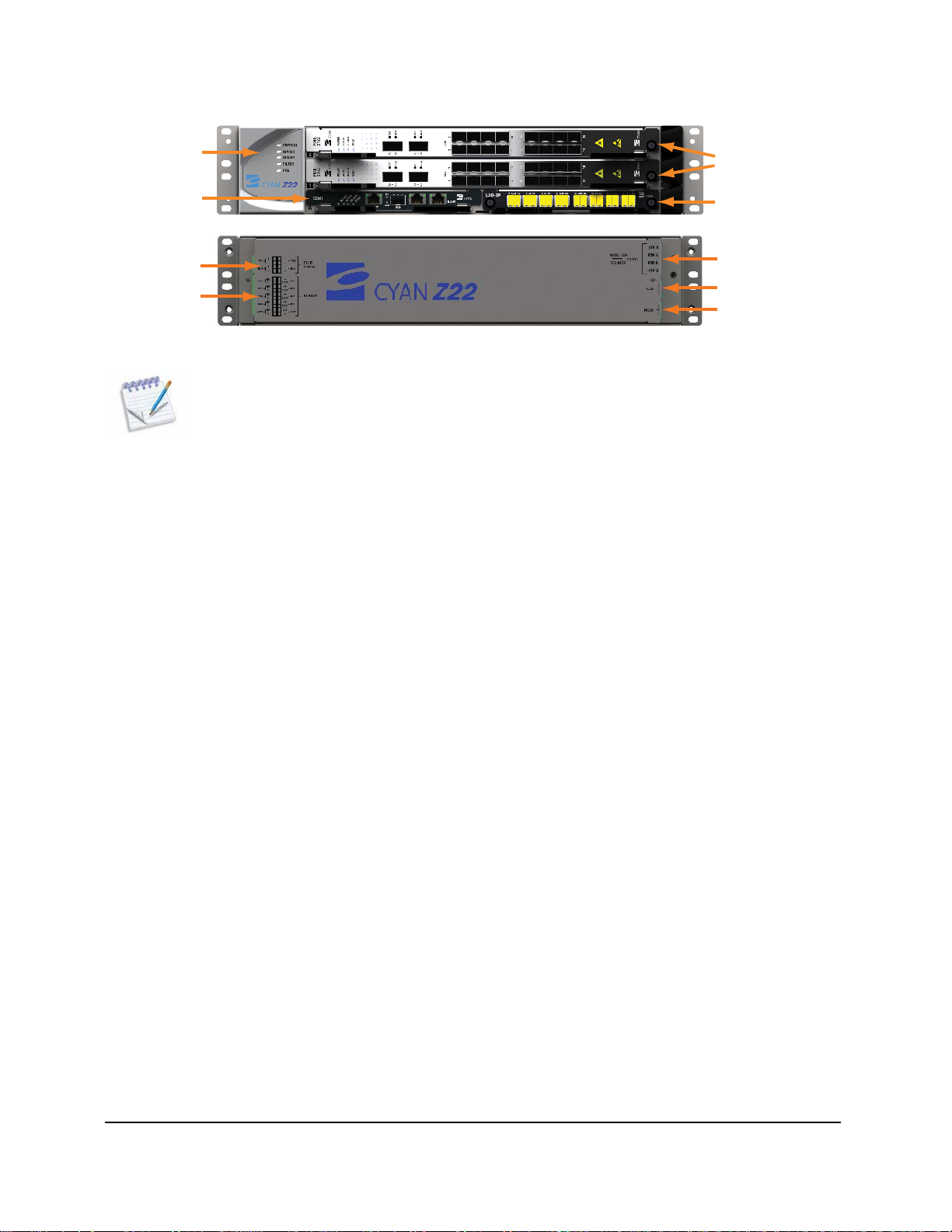
Figure 1: Front and Rear View of the Z22 -48V Shelf Layout
Note: The iLAN interface on the rear of the Z22 chassis is reserved for future use.
1.1.1 Z22 Shelf Description
The Z22 I-Temp system employs advanced technologies, with high-density modularity in a compact 2 RU
high, 19" (48.26 cm) wide chassis. Optimized for low entry costs, the Z22 shelf has two horizontal service
module slots and two common equipment slots supporting advanced services and network topologies.
• Line card (module) slots: 2
• Common control module slots: 2 (A and B)
Note: If the Z22 shelf is configured with an in-chassis LAD-2P or LAD-2G module, the module
must be installed in common control slot B.
• 1+1 equipment protection
• ITU timing
• All front access line cards and card interface connections
• All Z-Series modules are hot-swappable
• Power connectors: Dual-feed Quick-Connect Terminal Block
• Alarm connectors: Quick-Connect Terminal Block
• Management connectivity: RJ-45 (10/100/1000Base-T)
All shelf components are modular and can be removed and replaced in the field. This provides full
serviceability and a simple upgrade path for future expansion. Each Z22 shelf ships with the following
items:
• (1) Front protective shield
• (1) Cable management guide
• (2) 10-position plug terminal block, 3.81 mm, 16–28 AWG
• (2) 4-position plug terminal block, 3.81 mm, 16–28 AWG
• (1) Ground cable
• (1) Power cable assembly
• (1) Fan module
• (1) Fan air filter
Page 24 © 2013 Cyan, Inc. – All Rights Reserved. 700-0023-05-00 Rev. 1
Page 25
Cyan Z-Series Engineering and Planning Guide Release 5.0
Z22 shelves should be installed in accordance with the Cyan Z22 Installation and Safety Guide. This will
ensure correct installation of modules, all associated wire management, power and grounding requirements,
and related components.
Redundancy and Protection
• Redundant fans
• Redundant power connections
• Equipment Protection: 1:1 for all common cards and service modules
• Carrier Ethernet Protection:
IEEE 802.3ad Link Aggregation
IEEE 802.3Qay Path Protection
ITU-T G.8032 Ethernet Ring Protection
• SONET/SDH Protection:
1+1 APS/MSP
UPSR/SNCP
1.1.2 Z22 Card Installation Guidelines
Z22 shelf slot restrictions and line card placement guidelines are shown in the tables below. CEMi controller
cards can only be installed in slots A and B. If deploying the in-chassis LAD-2P or LAD-2G module, you
must install the LAD module in slot B.
+24V Z22 Shelf
The PME-216i +24V I-Temp line card is identical in function to the -48V I-Temp PME-216i line card, but is
designed to operate in 24-volt applications supported by the Z22 +24V model. Voltage range for the +24
Volt PME-216i line card is 18 to 30 Vdc.
Line Cards
CEMi X X
LAD-2P or LAD-2G X
PME-216i (+24V) X X
Important! – At least one PME-216i line card must be installed in slots 1 and/or 2 of the
+24V Z22 shelf to act as the shelf manager.
A B 1 2
Slots
700-0023-05-00 Rev. 1 © 2013 Cyan, Inc. – All Rights Reserved. Page 25
Page 26
Cyan Z-Series Engineering and Planning Guide Release 5.0
48V
-48V Z22 Shelf
Line Cards
A B 1 2
Slots
CEMi X X
LAD-2P or LAD-2G X
PME-216i (-48V)
X X
PME-412 X X
MSE-1482 X X
SFT-8
X X
2.5G-LME4 X X
SFT-10G16 X X
DTM-8 / DTM-8G
X X
DTM-100G X X
FLX-216i X X
WSS-402
X X
WSS-404 X X
Important! – At least one Z-Series line card must be installed in slots 1 and/or 2 of the Z22 shelf to act as the shelf manager.
Note: A dual-slot DTM-100G line card installed in slots 1 and 2 does NOT provide shelf manager
redundancy.
1.1.3 CEMi Controller Card: +24 Volt
The CEMi +24V model is identical in function to the -48V CEMi controller card, but is designed to operate
in 24-volt applications supported by the Z22 +24V shelf model. Voltage range for the +24 volt CEMi card is
18 to 30 Vdc.
For CEMi controller card feature details and specifications, see Common Equipment Module (CEMi)
starting on page 33.
1.1.4 Z22 Physical
• Height: 3.5" / 88.9 mm (2 RU)
• Width: 19.00" / 483 mm
• Depth: 14.85" / 377 mm
• Weight: 15 lbs. / 6.8 kg (with 2 CEMi cards and fan tray)
• Operating temperature: -40°F to +149°F / -40°C to +65°C (I-Temp)
Page 26 © 2013 Cyan, Inc. – All Rights Reserved. 700-0023-05-00 Rev. 1
Page 27
Cyan Z-Series Engineering and Planning Guide Release 5.0
NO
C
NO
C
NO
C
NC
C
NO
C
+
COM
+
COM
+
COM
+
COM
NO
C
CRIT
MAJ
MIN
FAIL
OUT2
IN1
IN2
IN3
IN4
OUT1
ALARMS
1.1.5 Z22 External Timing
The Z22 system supports the following timing inputs/outputs used for network synchronization:
• 2 T1/E1 outputs
• 2 T1/E1 inputs
The timing inputs and outputs are accessed through an 8-position pluggable terminal block on the rear side
of the Z22 chassis.
The following table shows the external timing connector pinouts:
Pin Description
1 T1/E1 TX1_+ (Output)
2 T1/E1 TX1_- (Output)
3 T1/E1 RX1_+ (Input)
4 T1/E1 RX1_- (Input)
1 T1/E1 TX2_+ (Output)
2 T1/E1 TX2_- (Output)
3 T1/E1 RX2_+ (Input)
4 T1/E1 RX2_- (Input)
1.1.6 Z22 Alarms
The Z22 platform supports system and environmental alarms. System alarms include Critical, Major,
Minor, and Failsafe. The environmental alarms include 4 inputs and 2 outputs. Alarms are accessed through
a combination 20-position pluggable terminal block on the rear side of the Z22 chassis.
Figure 2: Z22 System and Environmental Alarms Connection
700-0023-05-00 Rev. 1 © 2013 Cyan, Inc. – All Rights Reserved. Page 27
Page 28
Cyan Z-Series Engineering and Planning Guide Release 5.0
The following table shows the connector pinouts for the system and environmental alarms:
Pin Description Pin Description
1 CRIT_NO 1 IN1_+
2 CRIT_C 2 IN1_COM
3 MAJ_NO 3 IN2_+
4 MAJ_C 4 IN2_COM
5 MIN_NO 5 IN3_+
6 MIN_C 6 IN3_COM
7 FAIL_NC 7 IN4_+
8 FAIL_C 8 IN4_COM
9 OUT2_NO 9 OUT1_NO
10 OUT2_C 10 OUT1_C
For details on configuring environmental alarms, see the Cyan Z-Series Troub lesh ooting and Maintenance
Guide.
1.1.7 Z22 Shelf Power
Feeds:
Voltage range:
Max voltage:
Max current:
2 1-A & 1-B
-48V Configuration -40 to -60 Vdc Guaranteed Operation
+24V Configuration 18 to 30 Vdc Guaranteed Operation
-/+100 Vdc Non-operational, no damage
-48V Configuration 10 Amps
+24V Configuration 20 Amps
Note: Use Planet Design as a guideline based on the total configured system current draw.
You must size fuses according to NEC standards or local site practice.
Page 28 © 2013 Cyan, Inc. – All Rights Reserved. 700-0023-05-00 Rev. 1
Page 29
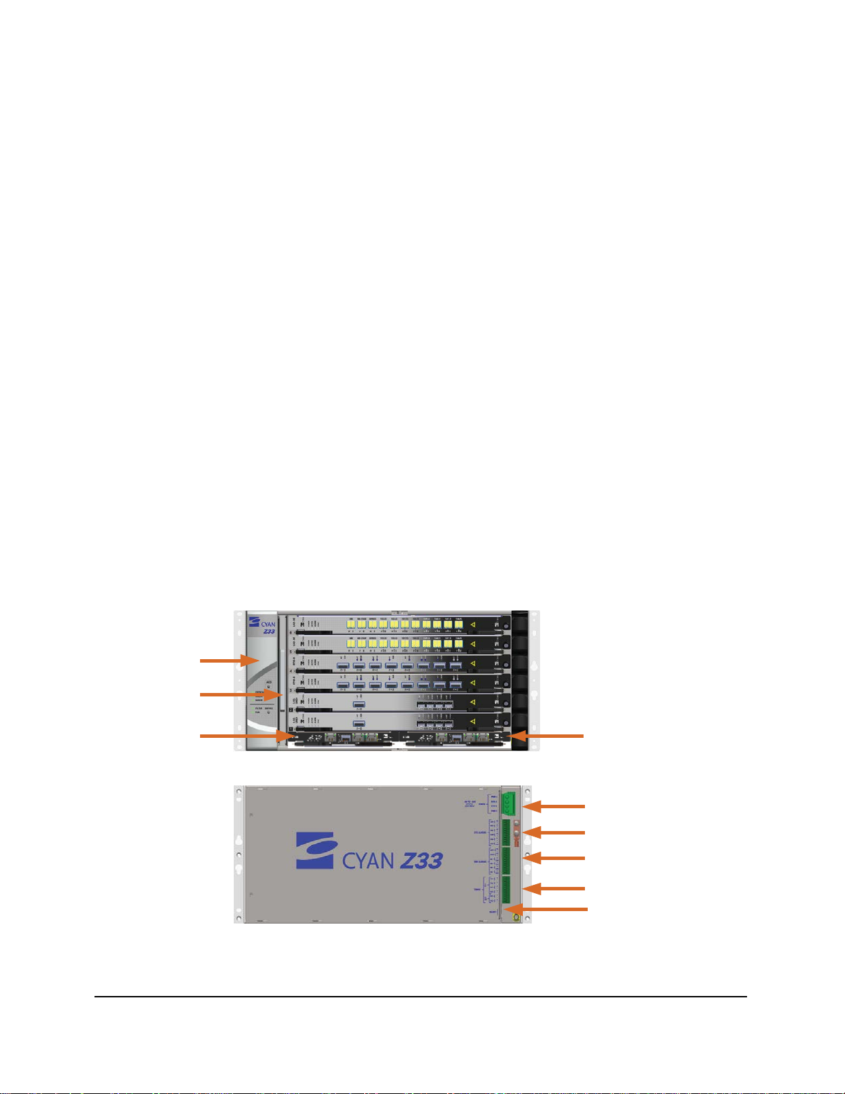
Cyan Z-Series Engineering and Planning Guide Release 5.0
Front View
Rear View
Fan Module
Fan Filter
CEMi A
Power
System Alarms
Environmental Alarms
Timing
Management Interface
CEMi B
1.2 Cyan Z33 Shelf
The Cyan Z33 Industrial Temperature (I-Temp), 400 Gbps packet-optical transport shelf is a compact,
cost-effective member of the Z-Series multi-layer transport networking platforms. The system provides
multi-layer add/drop multiplexing (MADM) and transport functions in one fully integrated system. The
system’s shared mesh protection provides full protection and sub-50 ms restoration for all services.
The Z33 shelf is a smaller version of the Z77 chassis intended for lower capacity and more cost-sensitive
edge applications. Z33 deployments enable service providers to scale packet services, leverage existing
services and infrastructure. It also optimizes their networks with multi-layer networking using 2.5G CWDM
and 10G DWDM transport.
A Z33 system equipped with Z-Series interchangeable trunk-side modules can be configured to support a
variety of network functions, including:
• Fully Reconfigurable Optical Add Drop Multiplexer (ROADM) with Optical-Optical-Optical
(OOO) switching and optical pass-through.
• Standalone SONET or SDH aggregation and transport.
• Packet switching providing advanced Layer 2 Ethernet services, access grooming and connection
oriented Ethernet.
• Efficient G.709 OTN grooming of the above services on to 10G multiservice wavelengths.
• Multi-channel DWDM with full optical add/drop multiplexing.
• CWDM channels of up to eight 2.5G wavelengths.
• Aggregation, grooming and STS-1 level switching of SONET/SDH and GbE services from existing
Ethernet switches, routers, DSLAMs, DLC/BLCs and third-party products.
• Transponding Gigabit Ethernet and OC-3/12/48 SONET STM-1/4/16 SDH services.
• Any combination of the above.
Figure 3: Z33 Front and Rear Shelf Layout
700-0023-05-00 Rev. 1 © 2013 Cyan, Inc. – All Rights Reserved. Page 29
Page 30

Cyan Z-Series Engineering and Planning Guide Release 5.0
Utilizing GbE and 10GbE switching and transport, the Z33 platform provides 2.5G CWDM transport, 10G
DWDM transport, OTN digital wrapper functionality, and multi-layer optimization and management.
The Z33, with a WSS-402 or WSS-404 module installed and paired with a passive AWG-40 optical patch
panel, provides a full ROADM with OOO switching and optical pass through. The WSS-402 provides 2
degrees and the WSS-404 provides 4 degrees of 40-wavelength cross-connect capacity in a single Z33 shelf.
Each WSS module provides optical add/drop multiplexing capability in the 1550nm band across
pre-defined ITU channel designations with 100 GHz spacing.
The shelf is optimized for edge and access node applications. The 5
RU chassis with six line card slots and
two common equipment modules can be equipped with any combination of Ethernet, CWDM, and DWDM
line cards to support a range of advanced services and applications. Further scalability is accomplished by
simply adding additional Z33 shelves or by redeploying interchangeable Z33 line cards into the
larger-capacity Z77 platform for increased aggregation and grooming.
The Z33 shelf provides the following key features:
• Supports 1 to 40 lambda 10G waves in ITU grid 100 GHz DWDM channel spacing.
• Supports CWDM (20nm spacing) capability with the addition of the LAC-8 module.
• Supports addition of 2.5G waves using SFT-8 modules.
• Supports 2-degree (East/West) configurations (WSS-402) or 4-degree (North/South/East/West)
configurations (WSS-404).
• 6 service slots, 2 Common Equipment Module (CEMi) slots (A and B).
• All Z-Series modules are hot-swappable.
• Over 100 Gbps per slot capacity.
• Service cards are common with the Z-Series platform. The CEMi controller cards are specific to the
Z33 and Z22 chassis.
The card/slot restrictions are as follows:
• Slots 1 and 2 must be the first slots that are occupied in the chassis.
• Slots 1 and 2 must contain a line card with management processing capability. These line cards
include: 2.5G-LME4, PME-412, PME-216i, DTM-8, DTM-8G, DTM-100G, SFT-8, SFT-10G16,
MSE-1482, WSS-402, and WSS-404 but not any LAD or LAC-8 modules.
Chassis Capacity
• Packet: Up to 240 Gbps of protected services
• Optical:
4-degree, 40-channel ROADM
4, 8, or 40 channel, C-Band Terminal Mux
Tunable or Fixed wavelength transceiver options
Redundancy and Protection
• Redundant fans
• Redundant power connections
• Equipment Protection: 1:1 for all common cards and service modules
Page 30 © 2013 Cyan, Inc. – All Rights Reserved. 700-0023-05-00 Rev. 1
Page 31

Cyan Z-Series Engineering and Planning Guide Release 5.0
• Carrier Ethernet Protection:
IEEE 802.3ad Link Aggregation
IEEE 802.3Qay Path Protection
ITU-T G.8032 Ethernet Ring Protection
• SONET/SDH Protection:
1+1 APS/MSP
UPSR/SNCP
1.2.1 Z33 Shelf Description
The Cyan Z33 I-Temp system employs advanced technologies, with high-density modularity in a compact
5
RU high, 19" (48.26 cm) wide chassis. Optimized for low entry costs, the Z33 shelf has six horizontal
service module slots and two common equipment slots supporting a wide range of advanced services and
network topologies.
• Line card (module) slots: 6
• Common control module slots: 2 (A and B)
• 1+1 equipment protection
• ITU timing
• All front access line cards and card interface connections
• Power connectors: Dual-feed Quick-Connect Terminal Block
• Alarm connectors: Quick-Connect Terminal Block
• Management connectivity: RJ-45 (10/100/1000Base-T)
All shelf components are modular and can be removed and replaced in the field. This provides full
serviceability and a simple upgrade path for future expansion. Each Z33 shelf ships with following items:
• (1) Front protective shield
• (1) Cable management guide
• (3) 12-position plug terminal block, 3.5 mm, 16–28 AWG
• (1) Ground cable
• (1) Power cable assembly
• (1) Fan module
• (1) Fan air filter
Z33 shelves should be installed in accordance with the Cyan Z33 Installation and Safety Guide. This will
ensure correct installation of modules, all associated wire management, power and grounding requirements,
and related components.
700-0023-05-00 Rev. 1 © 2013 Cyan, Inc. – All Rights Reserved. Page 31
Page 32

Cyan Z-Series Engineering and Planning Guide Release 5.0
1.2.2 Z33 Line Card Configuration Guidelines
Z33 slot restrictions and line card placement guidelines are shown in the table below. Note that slots A and
B are reserved for the Common Equipment Modules (CEMi’s) and are not shown in the table. Card pairs,
where applicable, can be installed in slot 1/2, 3/4, and 5/6.
Line Cards
2.5G-LME4 X X X X X X
DTM-8 X X X X X X
DTM-8G X X X X X X
DTM-100G X X X X X X
PME-216i X X X X X X
PME-412 X X X X X X
SFT-8 X X X X X X
SFT-10G16 X X X X X X
MSE-1482 X X X X X X
FLX-216i X X X X X X
WSS-402 X X X X X X
WSS-404 X X X X X X
LAD-4 X X X X
LAD-4A
LAD-8 X X X X
LAD-8A X X X X
1 2 3 4 5 6
Slots *
X X X X
LAD-8E
LAD-8i X X X X
LAD-8X X X X X
LAD-40 X X X X
LAD-40E
LAC-8 X X X X
X X X X
X X X X
* Shading indicates paired slots for applicable line cards.
At least one of the following line cards must be installed in slots 1 and/or 2 of the Z33 shelf:
• 2.5G-LME4 • PME-216i • MSE-1482
• DTM-8 • PME-412 • WSS-402
• DTM-8G • SFT-8 • WSS-404
• SFT-10G16 • FLX-216i • DTM-100G
When installed in slots 1 and/or 2, these cards also act as shelf managers.
Page 32 © 2013 Cyan, Inc. – All Rights Reserved. 700-0023-05-00 Rev. 1
Page 33

Cyan Z-Series Engineering and Planning Guide Release 5.0
point and ring topologies.
1.2.3 Common Equipment Module (CEMi)
The CEMi I-Temp controller card provides the timing subsystem, telco alarms, inventory management, fan
control, active/standby arbitration, and an integrated DCN for the Z22 and Z33 shelves.
• Power: 8 watts typical, 10 watts maximum
• Weight: 0.96 lbs. / 435 grams
• Height: 5.8" / 147 mm
• Depth: 11.5" / 292 mm
• Width: .9" / 23 mm
• Timing: Stratum 3
• Four Ethernet interfaces:
Craft: 1 x 10/100/1000Base-T RJ-45
iLAN: 2 x 10/100/1000Base-T RJ-45
DCN: 1 x 100Base-FX SFP
The Data Communication Network (DCN) 100Base-FX SFP port provides an optional method for
supporting DCN management connectivity to the node.
The iLAN Ethernet interfaces provide DCN connectivity and make use of OSPF routing (iLAN to iLAN
connection). The ports are typically connected to an Ethernet switch used for management networking. The
iLAN ports can also provide IP access to secondary shelves (Z22, Z77, and other Z33 nodes). For a
description of the Z77 iLAN ports, see BOSS Termination Module starting on page 131.
Figure 4: CEMi Controller Card
Note: A CEMi I-Temp controller card and a standard CEM C-Temp controller card can be
co-located in the same Z33 shelf.
Important! – Multiple connections from a single CEMi controller card to different
far-end CEMi controller cards is supported in both point-toHowever, multiple connections between the Ethernet ports (fiber or copper) of two
CEMi controller cards in the same shelf should be avoided as this can result in an
inadvertent Ethernet loop that could severely impact the performance of the system.
CEMi iLAN, DCN, and MSE-1482 Connectivity Options
The CEMi iLAN and DCN ports, in combination with the MSE-1482 line card, provide several connectivity
options and features depending on the application requirements and system configuration. Two example
configurations are described below.
When used with MSE-1482 line cards, the CEMi controller cards can provide management transport
connectivity instead of installing LAD modules which are typically configured to provide the shelf
connectivity. The CEMi controller card iLAN port provides the transport connectivity between MSE-1482
line cards installed at adjacent node locations.
700-0023-05-00 Rev. 1 © 2013 Cyan, Inc. – All Rights Reserved. Page 33
Page 34

Cyan Z-Series Engineering and Planning Guide Release 5.0
To Outside Fiber Plant To Outside Fiber Plant
MSE-1482 10G OTN
Fiber Ports
MSE-1482 1000Base-F
Copper Ports
CEMi iLAN Port
Slot B
CEMi iLAN Port
Slot A
To Outside Fiber Plant To Outside Fiber Plant
MSE-1482 10G OTN
Fiber Ports
CEMi DCN Port
Slot B
CEMi DCN Port
Slot A
Common
1310 1550
Common
1310 1550
Common
1310 1550
The figure below shows an example of connecting the CEMi iLAN port in slot A to an MSE-1482 GbE
copper port in slot 2 and the CEMi iLAN port in slot B to an MSE-1482 GbE port in slot 1. The MSE-1482
line card 10G OTN trunk interfaces integrate the CEMi with 10G traffic.
Communication is supported by connecting the CEMi iLAN port to a 1GE port on the MSE-1482 line card
as shown in the figure below. The MSE-1482 line card transports the traffic via Ethernet over SONET (EoS)
to a gateway node where the traffic is dropped locally to the customer’s management network.
Figure 5: CEMi and MSE-1482 Configuration - Traffic via EoS
The next figure shows an example of using two CEMi controller cards and two MSE-1482 line cards to
transport management traffic to a gateway node via a dedicated wavelength that is multiplexed using the
passive WDM Module 1310/1550nm LGX. At the gateway node the wavelength is de-muxed and the
management traffic dropped locally to the customer’s management network.
Figure 6: CEMi and MSE-1482 DCN Configuration Option
Page 34 © 2013 Cyan, Inc. – All Rights Reserved. 700-0023-05-00 Rev. 1
Page 35

Cyan Z-Series Engineering and Planning Guide Release 5.0
Physical connections in this example configuration are as follows:
1. Connect the CEMi DCN port in slot A to the 1550nm port of the WDM Module 1310/1550nm LGX.
2. Connect the CEMi DCN port in slot B to the 1550nm port of the WDM Module 1310/1550nm LGX.
3. Connect the MSE-1482 10G OTN fiber port in slot 1 to the 1310nm port of the WDM Module
1310/1550nm LGX.
4. Connect the MSE-1482 10G OTN fiber port in slot 2 to the 1310nm port of the WDM Module
1310/1550nm LGX.
5. Connect the outside plant fiber to the common port of the WDM Module 1310/1550nm LGX.
6. Connect the outside plant fiber to the common port of the WDM Module 1310/1550nm LGX.
For details on provisioning the CEMi DCN and the MSE-1482 10G OTN fiber port, see the Planet Operate
User Guide.
The WDM Module 1310/1550nm LGX is installed in an LGX shelf. For details on installing the LGX shelf
and LGX-compatible modules, see the Cyan Z33 Installation and Safety Guide or the Cyan Z77 Installation
and Safety Guide.
CEMi Specifications
Power consumption:
Weight:
Height:
Depth:
Width:
Timing:
Craft:
iLAN:
Management:
Operating temperature:
8 Watts (typical), 10 Watts (maximum)
0.96 lbs. / 435 grams
5.8" / 147 mm
11.5" / 292 mm
0.9" / 23 mm
Stratum 3
1 x 10/100/1000Base-T RJ-45
2 x 10/100/1000Base-T RJ-45
1 x 100Base-FX SFP
-40°F to +149°F / -40°C to +65°C (I-Temp)
1.2.4 Z33 Timing
The Z33 system supports the following timing inputs/outputs used for network synchronization:
• Two DS1/E1 outputs (ITU G.707, Telcordia GR-440)
• Two DS1/E1 inputs (ITU G.707, Telcordia GR-440)
• Two CC/2M inputs (ITU G.707)
The timing inputs and outputs are accessed through a 12-position pluggable terminal block on the rear side
of the Z33 chassis. The following table shows the external timing connector pinouts:
Pin Description
1 T1/E1 TX1_+ (Output)
2 T1/E1 TX1_- (Output)
3 T1/E1 TX2_+ (Output)
4 T1/E1 TX2_- (Output)
5 T1/E1 RX1_+ (Input
6 T1/E1 RX1_- (Input)
700-0023-05-00 Rev. 1 © 2013 Cyan, Inc. – All Rights Reserved. Page 35
Page 36

Cyan Z-Series Engineering and Planning Guide Release 5.0
Pin Description
7 T1/E1 RX2_+ (Input)
8 T1/E1 RX2_- (Input)
9 CC/2M RX1_+ (Input)
10 CC/2M RX1_- (Input)
11 CC/2M RX2_+ (Input)
12 CC/2M RX2_- (Input)
1.2.5 Z33 Alarms
The Z33 platform supports system and environmental alarms. System alarms include Critical, Major,
Minor, Audible, Failsafe, and ACO. The environmental alarms include 4 inputs and 2 outputs. Alarms are
accessed through a 12-position pluggable terminal block on the rear side of the Z33 chassis.
The following table shows the connector pinouts for the system and environmental alarms:
System Alarm Connector Pinout
Pin Description
1 CRIT_NO
2 CRIT_C
3 MAJ_NO
4 MAJ_C
5 MIN_NO
6 MIN_C
7 AUD_NO
8 AUD_C
9 FAIL_NC
10 FAIL_C
11 ACO_+
12 ACO_COM
For details on configuring environmental alarms, see the Troubleshooting and Maintenance Guide.
Environmental Alarm Connector Pinout
Pin Description
1 OUT1_NO
2 OUT1_C
3 OUT2_NO
4 OUT2_C
5 IN1_+
6 IN1_COM
7 IN2_+
8 IN2_COM
9 IN3_+
10 IN3_COM
11 IN4_+
12 IN4_COM
1.2.6 Z33 Shelf Power
Feeds:
Voltage range:
Max voltage:
Max current:
2 1-A & 1-B
-40 to -60 Vdc Guaranteed Operation
-/+100 Vdc Non-operational, no damage
24 Amps
Note: Use Planet Design as a guideline based on the total configured system current draw.
You must size fuses according to NEC standards or local site practice.
Page 36 © 2013 Cyan, Inc. – All Rights Reserved. 700-0023-05-00 Rev. 1
Page 37

Cyan Z-Series Engineering and Planning Guide Release 5.0
Operations
Panel
Front Rear
Air Filter Tray
Fan Modules
Rear Filler Plate
BTM
RCMs
Power
1.2.7 Z33 Physical
Height:
Width:
Depth:
Weight:
Operating temperature:
8.75" / 222 mm (5 RU)
19.00" / 483 mm
14.85" / 377 mm
27 lbs. / 12.25 kg (chassis, 2 x CEMi cards, and fan tray)
-40°F to +149°F / -40°C to +65°C (I-Temp)
1.3 Cyan Z77 Shelf v2
Equipped with an optimized-mesh Optical Transport Network (OTN) switching fabric, the Cyan Z77
platform provides high performance for multiple traffic types. Z77 systems support real-time, streaming and
large bandwidth services by optimizing optical and packet layers for flexible multi-service transport ranging
from Metro Ethernet, to SONET/SDH, and wavelength services. The Z77 shared mesh protection provides
full protection and sub-50 ms restoration for all services.
The Z77 chassis utilizes a mid-plane architecture and provides sixteen line card slots. All chassis
components (including the Operations Panel) are modular and can be removed or replaced in the field. This
provides full serviceability and a simple upgrade path for future expansion. Line cards for management,
DWDM, CWDM, and client services insert in the sixteen front slots. All Z-Series modules are
hot-swappable.
Up to three Z77 shelves can be installed into a typical seven-foot equipment rack. All system functionalities
are modular so that each node has the optimal mix of optical bandwidth, service interfaces, and service
aggregation/grooming.
Z77 shelf v2 configurations range from dense optical-optical-optical (OOO) all optical junctions, to
optical-electrical-optical (OEO)-based aggregation and grooming nodes and small flexible OOO/OEO
hybrid nodes at access locations. The Z77 platform can scale from small spurs and access rings to dense
optical thoroughfares and head-end locations.
Figure 7: Z77 Shelf v2 – Front and Rear Views
The Z77, with a WSS-402 or WSS-404 module installed and paired with a passive AWG-40 optical patch
panel, provides a full ROADM with Optical-Optical-Optical (OOO) switching and optical pass through.
The WSS-402 provides 2 degrees and the WSS-404 provides 4 degrees of 40-wavelength cross-connect
capacity in a single shelf. Each WSS module provides optical add/drop multiplexing capability in the
1550nm band across pre-defined ITU channel designations with 100 GHz spacing.
700-0023-05-00 Rev. 1 © 2013 Cyan, Inc. – All Rights Reserved. Page 37
Page 38

Cyan Z-Series Engineering and Planning Guide Release 5.0
Each Z77 shelf v2 ships with following items:
• (1) Operations Panel
• (1) Fan Filter
• (2) Fan Modules
• (2) -48V Power Entry Modules (PEMs)
• Front and Rear cable management trays and covers as required
• Air Management Boards (AMBs)
Note that each shelf is shipped with enough AMBs for all unused openings in the chassis.
• (4) Rear Closure Modules (RCMs) or (4) XC-2800 switch fabric modules
RCMs or the XC-2800 switch fabric are required for PME-412, PME-216i, and/or 2.5G-LME4
applications. For example, ODU1 express cross-connects between a pair of 2.5G-LME4 line cards
or LAG member ports between a pair of PME line cards. RCMs are required for MSE-1482 (MSE
cross-card connections, pass-through traffic, and SONET/SDH protection groups) applications. For
additional information on the RCMs, see Ring Closure Modules starting on page 135.
MSE-1482 line cards can be installed in a Z77 shelf supported by the XC-2800 switch fabric. The
XC-2800 switch fabric module provides supports the MSE-1482 in a standalone muxponder
configuration. However, the XC-2800 switch fabric module does not support MSE-1482
card-to-card backplane cross-connections or protection.
To support the TSW-10G10, PSW-10G10, and PSW-618 line cards, the Z77 shelf must be
configured with XC-2800 switch fabric modules. For additional information, see XC-2800 Switch
Fabric starting on page 135.
Z77 shelves should be installed in accordance with the Cyan Z77 Installation and Safety Guide. This
ensures correct installation of modules, all associated wire management, power and grounding
requirements, and related components.
Note: The Z77 s helf v2 requires CyOS software Release 3.0 or higher. A Z77 shelf configured with
XC-2800 switch fabric modules requires CyOS software Release 4.0 or higher.
Features and Benefits
The Cyan Z77 packet-optical transport platform provides a range of features and benefits:
• Flexible platform architecture supports scalability for investment protection, common sparing /
inventory, operational consistency and functionality.
• Pair switch cards to support equipment redundancy and increase switch capacity.
• Supports up to 2.8 Tbps of non-blocking packet and/or OTN switch capacity with any-to-any packet
cross-connect (switching) for point to multipoint services, grooming and transport efficiency.
• 4-degree, 40-channel ROADM functionality for OOO capability and network flexibility.
• Fixed-wavelength 4, 8, or 40 channel DWDM for economic efficiency.
• Over 200 Gbps per slot capacity to support 100G modules.
• Multi-layer transport integration provides significant network efficiencies.
Full-mesh passive optical backplane eliminates external patching.
OTN on all trunk connections for enhanced performance and management on all services.
Page 38 © 2013 Cyan, Inc. – All Rights Reserved. 700-0023-05-00 Rev. 1
Page 39

Cyan Z-Series Engineering and Planning Guide Release 5.0
Integration across Ethernet, SONET/SDH, COE, OTN and DWDM provides multi-layer
network visibility.
Efficient network planning, design and operation. Resulting network visibility enables
multi-layer A to Z provisioning for fast, reliable service activation per modeled network plans
with Planet Operate.
• All Z-Series modules are hot-swappable.
Chassis Capacity
• When equipped with the XC-2800 switching fabric, the Z77 supports up to 2.8 Tbps of packet or
OTN switch capacity per shelf, or a concurrent mix of both.
• Optical:
4-degree, 40-channel ROADM
4, 8, or 40 channel, C-Band Terminal Mux
Tunable or Fixed wavelength transceiver options
Redundancy and Protection
• Redundant fans
• Redundant power connections
• Equipment protection:
1:1 for all common cards and service modules
1:3 for multi-technology switch fabric modules
• Carrier Ethernet Protection:
IEEE 802.3ad Link Aggregation
IEEE 802.3Qay Path Protection
ITU-T G.8032 Ethernet Ring Protection
• SONET/SDH Protection:
1+1 APS/MSP
UPSR/SNCP
Power Entry Modules
Each Z77 shelf v2 has dual -48V power supplies located on the rear of the chassis. Each Power Entry
Module (PEM) accepts four feeds for a total of eight feeds. These eight feeds are distributed across the line
card slots in a redundant fashion, so that even if a line card failure shorted two feeds, the rest of the shelf will
still have power.
700-0023-05-00 Rev. 1 © 2013 Cyan, Inc. – All Rights Reserved. Page 39
Page 40

Cyan Z-Series Engineering and Planning Guide Release 5.0
1.3.1 Z77 Card Installation Guidelines
Z77 slot restrictions and line card placement guidelines are shown in the table below. Note that slots 1 and 2
are reserved for the BOSS/BOSS2 cards and are not shown in the table. Card pairs, where applicable, can be
installed in slots 3/4, 5/6, 7/8, 9/10, 11/12, 13/14, and 15/16.
Line Cards
3 4 5 6 7 8 9 10 11 12 13 14 15 16
2.5G-LME4 X X X X X X X X X X X X X X
DTM-8 X X X X X X X X X X X X X X
DTM-8G X X X X X X X X X X X X X X
DTM-100G X X X X X X X X X X X X X X
LAD-4 X X X X X X X X X X X X X X
LAD-4A X X X X X X X X X X X X X X
LAD-8 X X X X X X X X X X X X X X
LAD-8A X X X X X X X X X X X X X X
LAD-8E X X X X X X X X X X X X X X
LAD-8i X X X X X X X X X X X X X X
LAD-8X X X X X X X X X X X X X X X
LAD-40 X X X X X X X X X X X X X X
LAD-40E X X X X X X X X X X X X X X
LAC-8 X X X X X X X X X X X X X X
PME-412 X X X X X X X X X X X X X X
PME-216i X X X X X X X X X X X X X X
TSW-10G10 X X X X X X X X X X X X X X
PSW-10G10 X X X X X X X X X X X X X X
PSW-618 X X X X X X X X X X X X X X
SFT-8 X X X X X X X X X X X X X X
SFT-10G16 X X X X X X X X X X X X X X
MSE-1482 X X X X X X X X X X X X X X
FLX-216i X X X X X X X X X X X X X X
WSS-402 X X X X X X X X X X X X X X
WSS-404 X X X X X X X X X X X X X X
Slots *
* Shading indicates paired slots for applicable line cards.
Individual Z-Series line cards are described in Z-Series Line Cards, Modules, and Optics starting on page 47.
For information on recommended slot assignments for LAD modules, WSS modules, and service card pairs, see
Best Practices for Network Configurations starting on page 199.
All modules are hot-swappable.
Page 40 © 2013 Cyan, Inc. – All Rights Reserved. 700-0023-05-00 Rev. 1
Page 41

Cyan Z-Series Engineering and Planning Guide Release 5.0
1.3.2 Z77 Power
Feeds:
Voltage range:
Max voltage:
Max current:
8 4-A & 4-B
-40 to -60 Vdc Guaranteed Operation
-/+100 Vdc Non-oper atio nal, no damage
96 Amps 24 Amps per feed
For details on Z77 DC power distribution across the shelf slots, see Z77 Fuse Positions and DC Feeds
starting on page 178.
Note: Use Planet Design as a guideline based on the total configured system current draw.
You must size fuses according to NEC standards or local site practice.
1.3.3 Z77 Physical
Height:
Width:
Depth:
Weight:
Common control slots:
Line card slots:
Fabric slots:
Power Entry Modules:
Operating temperature:
22.75" / 577.8 mm (13 RU)
21.00" / 533.4 mm (23" / 600 mm compatible)
21.00" / 533.4 mm
98 lbs / 44.5 kg
2
14
4
2
+32°F to +122°F / 0°C to +50°C
1.3.4 Z77 Timing
• Stratum 3 compliant timing subsystem
• Redundant DS1 and 2MHz timing inputs
• Derived DS1 timing outputs
• Line-timed SONET/SDH support
1.3.5 Z77 Management
• 4 x 10/100/1000Base-T DCN interfaces
• System alarm outputs (Critical, Major, Minor, Audible, Failsafe)
• System alarm inputs (ACO)
• Two provisionable environmental alarm outputs
• Five provisionable environmental alarm inputs
700-0023-05-00 Rev. 1 © 2013 Cyan, Inc. – All Rights Reserved. Page 41
Page 42

Cyan Z-Series Engineering and Planning Guide Release 5.0
1.4 Cyan L-AMP Shelf
The Cyan Z-Series Lambda Amplifier (L-AMP) is a fully self-contained 1 RU module that functions as a
bi-directional mid-span optical amplifier / repeater. Each L-AMP shelf supports bi-directional physical
layer amplification of multiple DWDM wavelengths where node-to-node optical spans are greater than
80 kilometers.
Traffic enters the L-AMP shelf from an East or West Cyan node, is appropriately attenuated, and processed
through a high performance two-stage Erbium Doped Fiber Amplifier (EDFA) for transmission to an
upstream Cyan Z-Series platform.
The shelf also provides a 1510nm add/drop port to support an Optical Supervisory Channel (OSC) carrying
Ethernet traffic for OAM.
The L-AMP shelf has all access on the front. It is designed to fit into 19-inch equipment racks, but has
extension mounting brackets for 23-inch rack installation.
Figure 8: L-AMP Shelf – Front View
Connectors on the L-AMP shelf include four types:
• System alarm outputs
• Environmental alarm inputs and outputs
• Ethernet ports (2)
• RS-232 port (reserved for future use)
The following table shows the L-AMP connection types, number / detail, and physical connectors:
Connection Type Number Connector
2 – Outputs
3 – Inputs
Alarms
Ethernet
(Management and Craft)
RS-232
(Reserved for future use)
1 – Audible
1 – ACO
1 – Fail Over
2 RJ-45
1 RJ-45
Terminal Block
Page 42 © 2013 Cyan, Inc. – All Rights Reserved. 700-0023-05-00 Rev. 1
Page 43

Cyan Z-Series Engineering and Planning Guide Release 5.0
TX Tap
Variable
Optical
Attenuator
EDFA
Variable
Optical
Attenuator
EDFA
1510 nm
OSC
SFP
1510 nm
OSC
SFP
RX
RX
DCF
In
DCF
Out
DCF
Out
DCF
In
TX
TX
East
Optical
Supervisory
Channel
West
Optical
Supervisory
Channel
RX
Mon
RX Tap
TX
Mon
TX Tap
RX
Mon
RX Tap
TX
Mon
West
East
1510nm
Add
1510nm
Drop
1%
Tap
1%
Tap
1510nm
Add
1510nm
Drop
The graphic below shows the L-AMP block diagram.
Figure 9: L-AMP Block Diagram
1.4.1 L-AMP Shelf Pinouts
The L-AMP shelf pinouts for the input and output alarms connector are shown in the following tables:
Input Alarms Connector
Pin Description
The external alarm inputs and outputs are all software configurable.
8 IN3_COM
7 IN3_+
6 IN2_COM
5 IN2_+
4 IN1_COM
3 IN1_+
2 ACO_COM
1 ACO_+
Output Alarms Connector
Pin Description
8 FAIL_COM
7 FAIL_NC
6 AUD_COM
5 AUD_NO
4 OUT2_COM
3 OUT2_NO
2 OUT1_COM
1 OUT1_NO
700-0023-05-00 Rev. 1 © 2013 Cyan, Inc. – All Rights Reserved. Page 43
Page 44

Cyan Z-Series Engineering and Planning Guide Release 5.0
1.4.2 L-AMP Interfaces
Ethernet Interfaces
The two Ethernet interfaces provide autosensing 10/100/1000 Mbps Ethernet connectivity. The Ethernet
ports are labeled MGMT and CRAFT:
• MGMT: The shelf management port is used to access the Data Communication Network (DCN)
that is available over the DWDM interfaces. The port is typically connected to an Ethernet switch
used for management networking.
• CRAFT: You can connect a laptop PC to the shelf craft port for a direct connection to commission
and recommission the L-AMP module.
Optical Interfaces and Access
• 4 optical fiber interfaces
• Optical Supervisory Channel (OSC) – 100Base-FX Ethernet at 1510nm
• Physical: Front access
Optical Specifications
• Channels/Frequency
40 C-band optical channels on 100 GHz ITU (1530.33 to 1561.42nm)
1510nm Optical Supervisory Channel (OSC) 100Base-FX Ethernet
• Minimum BER: 1x10-12
• DWDM Power Output
40 Channels
13.0 dBm (-3 dBm per channel)
• Laser Safety Class:1
• Laser Shutdown\Restart: automatic, ITU-T G.664
• Channel Frequency Tolerance: .00052%
• Dispersion Compensation: External
• Maximum span of 32 dB, supports up to 25 dB of gain
• Transmit Power up to 20 dBm
• Mid-stage loss support for 0 – 8.5 dB
• Monitor ports — about 20 dB lower than the respective TX and RX Line port
Note: The L-AMP supports manual gain tilt control. Gain tilt can occur when channel gain is not
flat upon reaching the optical amplifier. In this situation, higher signals receive more power,
while lower signals receive less power.
Page 44 © 2013 Cyan, Inc. – All Rights Reserved. 700-0023-05-00 Rev. 1
Page 45

Cyan Z-Series Engineering and Planning Guide Release 5.0
Maximum TX Power:
1.4.3 L-AMP OSC Specifications
Frequency:
Data Format:
Minimum TX Power:
Maximum RX Power:
Minimum RX Power:
OSC Link Budget:
Note: If you are using CyOS 3.x, RX power at -10 dBm or higher will raise a High RX power
alarm. If you are using CyOS 4.0, RX power at -10 dBm or higher does not raise a High RX power
alarm, but an "Out of Range – High" notification will be displayed in Planet Operate in the
Transport Resources tab for the L-AMP OSC.
198.5 THz 1510nm
100Base-FX Ethernet
5 dBm
-1 dBm
-3 dBm
-33 dBm
8 – 32 dB
1.4.4 L-AMP Features
• All access on front panel
• 1
RU x 19 inches wide (with mounting brackets for 23-inch racks)
• 40ch + OSC: 80 km amplifier
• Remotely managed via OSC
• Craft interface
• Management LAN available for other devices
• Four alarm input/output contacts
• Mid-stage DCM access and monitor ports
• Redundant power
• Hot swap fan module (3 x fans)
• Managed through Planet Operate, CLI, TL1, and SNMP v2
1.4.5 L-AMP Applications
1.4.6 L-AMP Physical
700-0023-05-00 Rev. 1 © 2013 Cyan, Inc. – All Rights Reserved. Page 45
• Extended optical reach of DWDM transport
• Management LAN and alarm extension
• Height: 1.735" (44.069 mm)
• Width: 18.31" (465.074 mm)
• Depth: 11.98" (304.29 mm)
• Weight: 10 lbs (4.55 kg)
Page 46

Cyan Z-Series Engineering and Planning Guide Release 5.0
1.4.7 L-AMP Power
Feeds:
Voltage Range:
Max Voltage:
Power
Consumption:
Max Current:
4 2-A & 2-B
-40 to -60 Vdc Guaranteed Operation
-/+100 Vdc Non-operational, no damage
50 W
80 W
2 Amps
Typical
Maximum
1.4.8 L-AMP Compliance
• NEBS 3 Certified (GR-63 CORE, GR-1089)
• UL/CSA Listed
• UE/CE-Marked: EN 60950, EN 55022, EN 6 1000, ETSI EN 300 386 V.1.3.3
• CB Scheme Certified 60950
• FCC, Subpart B, Part 15, Class A
• RoHS compliant
Page 46 © 2013 Cyan, Inc. – All Rights Reserved. 700-0023-05-00 Rev. 1
Page 47

Chapter 2: Z-Series Line Cards, Modules, Optics, and Optical Protection
This section describes each Cyan Z-Series line card, related XFP/SFP transceivers, Z-Series modules,
optical protection groups, and the Optical Protection Switch.
Cyan Z-Series systems provide an effective and economically efficient approach to scaling network
capacity while simplifying planning and operations. Optimized for packet and the transition of TDM to
packet, the Z-Series platforms support advanced Ethernet switching and transport over connection-oriented
Ethernet (COE), SONET/SDH, or wavelengths.
Recognizing the continuing role of TDM in many networks, the Z-Series platform optionally supports
advanced SONET/SDH aggregation and transport functionality. Rounding out support for wholesale,
wavelength services and the need to muxpond and transpond certain services, the Z-Series supports a
complete range of transport requirements. Driven by IPTV, VOD, 2/3/4G wireless backhaul, carrier
Ethernet and scaling Internet services, the Z-Series grooms services into discrete high-capacity 10G
wavelengths. As services scale, the Z-Series platform provides the option to transport multiple 10G
wavelengths per fiber using Dense Wavelength Division Multiplexing (DWDM). The Z-Series DTM-100G
module provides 100G transport services. The DTM-100G is fully compatible with existing Z-Series
DWDM components including LAD modules and WSS ROADM modules. This allows the mixing of 10G
and 100G waves over the same fiber.
Addressing the multi-layer aspect of evolving networks, the Z-Series provides multi-layer add/drop
multiplexing (MADM) and transport functions in one fully integrated system, supporting:
• GbE and 10GbE switching and transport
• SONET/SDH aggregation and transport
• OTN (digital wrapper) functionality
• 100G DWDM transport
• 10G DWDM transport
• 2.5G CWDM transport
• Multi-layer optimization and management
700-0023-05-00 Rev. 1 © 2013 Cyan, Inc. – All Rights Reserved. Page 47
Page 48

Cyan Z-Series Engineering and Planning Guide Release 5.0
XFP, SFP, and SFP+ Transceivers ........................................................ 143
• OTN-level multiplexing GbE, OC-3/STM-1, OC-12/STM-4, and OC-48/STM-16 signals into
OTU2 signals
• Line cards and modules provide all functionality for the Z-Series nodes. By varying the line cards
selected for a node, a Z-Series shelf is configurable to support a wide range of site requirements.
For additional information and instructions on installing Z-Series line cards, see the Cyan Z22 Installation
and Safety Guide, the Cyan Z33 Installation and Safety Guide, or the Cyan Z77 Installation and Safety
Guide. For information on provisioning Z-Series line cards, see the Planet Operate User Guide or the Cyan
Packet Switching User Guide.
In This Chapter
LAD Modules .......................................................................................... 49
DTM-8 and DTM-8G Transponder Modules .......................................... 61
2.5G-LME4 Multiplex-Transponder Module .......................................... 66
PME-412 Packet Multiplexer Module..................................................... 69
PME-216i Packet Multiplexer Module ................................................... 75
PSW-10G10 Packet Module ................................................................... 82
PSW-618 Packet Module ........................................................................ 87
TSW-10G10 Packet Aggregation and Transport Module ....................... 91
LAC-8 Lambda Aggregator Module ....................................................... 94
LAC-4P Lambda Aggregator CWDM Terminal Multiplexer Module ... 97
SFT-8 Module Transponder Module ....................................................... 98
SFT-10G16 Multi-Rate Transponder Module ....................................... 102
DTM-100G Transponder Module ......................................................... 105
MSE-1482 Multiservice SONET/SDH Aggregation and Transport ..... 110
FLX-216i Multi-Rate OTN Muxponder Module .................................. 116
WSS-402 and WSS-404 Wavelength Selective Switch Modules ......... 120
Broadband Operating System Supervisor ............................................. 129
BOSS Termination Module ................................................................... 131
Line Card SYNC LED .......................................................................... 134
Ring Closure Modules ...........................................................................
XC-2800 Sw
itch Fabric ......................................................................... 135
Optical Protection Groups ..................................................................... 138
Optical Protection Switch ...................................................................... 141
135
Page 48 © 2013 Cyan, Inc. – All Rights Reserved. 700-0023-05-00 Rev. 1
Page 49

Cyan Z-Series Engineering and Planning Guide Release 5.0
2.1 LAD Modules
The 2-channel, 4-channel, 8-channel, and 40-channel Cyan Z-Series Lambda Add/Drop (LAD) 100 GHz
modules provide DWDM connectivity using thin film filter technology and optional EDFA amplification.
The modules utilize standard ITU 100 GHz channel spacing. An environmentally hardened 8-channel
module (LAD-8i) is also available for deployments in remote cabinets with the Cyan Z33 I-Temp shelf.
LAD modules provide an Optical Supervisory Channel (OSC) 100Base-FX Ethernet management channel.
The purpose of the Ethernet management channel is inter-node communication, but it can also be used to
carry other management traffic from third-party systems if an out-of-band DCN network is required.
Note: The LAD-2P and LAD-2G modules, deployed in Z22 systems, do not provide an OSC. In Z22
configurations, the PME-216i line card has an in-band management channel to provide inter-node
communication.
Several versions of the optical LAD modules are available:
• LAD-2P: 2-channel (I-Temp)
Note: The LAD-2P module provides East and West DWDM add/drop channels and standard
1310nm add/drop ports for the Z22 shelf.
• LAD-2G 2-channel (I-Temp)
Note: The LAD-2G module provides three long-reach wavelengths; East and West DWDM
add/drop channels and standard 1550nm add/drop ports for the Z22 shelf.
• LAD-4: 4-channel
• LAD-4A: 4-channel with booster amplifier
• LAD-8: 8-channel
• LAD-8i: 8-channel (I-Temp)
• LAD-8A: 8-channel with booster amplifier
• LAD-8E: 8-channel with pre-amp and booster amplifier
• LAD-8X: 8-channel with pre-amp and booster amplifier (40dB reach)
• LAD-40: 40-channel
• LAD-40E: 40-channel with pre-amp and booster amplifier
700-0023-05-00 Rev. 1 © 2013 Cyan, Inc. – All Rights Reserved. Page 49
Page 50

Cyan Z-Series Engineering and Planning Guide Release 5.0
The following figures show some examples of the various LAD modules.
Figure 10: Cyan Z22 LAD-2P Module
Figure 11: Cyan Z-Series LAD-4A Module
Figure 12: Cyan Z-Series LAD-8i Module
Figure 13: Cyan Z-Series LAD-40E Module
For detailed information on optical link design for LAD modules, see Optical Link Design starting on page 145.
Note: LAD-8 to LAD-8A links are not supported.
LAD-40 and LAD-40E Modules Paired with the AWG-40
LAD-40 and LAD-40E modules require an associated AWG-40 Array Wave Guide module for add/drop
traffic. Individual wavelengths are added and/or dropped using the passive AWG-40 2
RU module. The
AWG-40 provides the ability to multiplex and de-multiplex any of the 40 channels supported by a LAD-40
or LAD-40E module. The AWG-40 module is connected to the LAD-40 or LAD-40E COM port through a
fiber jumper. The individual channels on the AWG-40 module are then connected to the appropriate
Z-Series line card DWDM XFP transceiver using a fiber jumper.
Page 50 © 2013 Cyan, Inc. – All Rights Reserved. 700-0023-05-00 Rev. 1
Page 51

Cyan Z-Series Engineering and Planning Guide Release 5.0
AWG-40 Array Wave Guide
Z33 Shelf
AWG-40 Module
LAD-40E Mid-Stage port
connects to DCM
LAD-40E Line port
connects to trunk
Notes:
LAD-40E Modules
Horizontal Fiber
Management Panel
Horizontal Fiber
Management Panel
AWG-40 Module
DCMs
CYANOPTICS CYANOPTICS
PME-412 Modules
Figure 14: AWG-40 External Module
Dispersion Compensating Modules (DCMs) may be used to support the LAD-40E module. The DCMs are
based on Fiber Bragg Gratings (FBGs) and exhibit lower loss than standard fiber-based DCMs. The DCMs
are housed in a standard LGX module, allowing three DCMs to be installed in a 1
RU, 19-inch rackmount
shelf/frame. The DCMs are connected to the LAD-40E Mid-stage port using a fiber jumper.
Note: If a DCM is required with a LAD-40E module, you must use a Fiber Bragg Grating DCM. If a
DCM is not required for your configuration, a 3dB loopback attenuator must be connected to the
LAD-40E Mid-stage port. The loopback attenuator is provided as part of the LAD-40E Fiber Jumper
Kit. For additional information on available DCMs, see Dispersion Compensation Modules
starting on page 151 in this guide.
The configuration example below shows two LAD-40E modules installed in a Z33 shelf and connected to
two AWG-40 modules and DCMs.
For details on provisioning cross-connects or using the A-to-Z provisioning tool for the LAD-40/LAD-40E
modules, AWG-40 modules, and associated Z-Series line cards, see the Planet Operate User Guide.
700-0023-05-00 Rev. 1 © 2013 Cyan, Inc. – All Rights Reserved. Page 51
Figure 15: LAD-40E and AWG-40 Installation Example
Page 52

Cyan Z-Series Engineering and Planning Guide Release 5.0
LAD-2P LGX Module
Cyan also provides an external LAD-2P LGX terminal multiplexer module. The LAD-2P LGX is designed
to be used in OEO networks. The module is housed in an industry standard LGX form factor. The passive
LAD-2P LGX module provides two (East and West) DWDM channels of add/drop capacity and a 1310nm
add/drop port.
Channel spacing is at 100 GHz. The LAD-2P LGX module provides two DWDM channels:
• Channel 30 – 1553.33nm, 193.0 THz
• Channel 31 – 1552.52nm, 193.1 THz
Figure 16: LAD-2P LGX Passive Module
1310nm Add/Drop Port
The LAD-8i module and the LAD-2P modules (in-chassis LAD-2P line card and the external LAD-2P
LGX) provide a standard 1310nm add/drop port, typically used for local client-side interfaces. The
client-side equipment may include various types of SONET/SDH, Ethernet, or OTN interfaces operating at
the 1310nm wavelength.
The LAD-8i and LAD-2P 1310nm add/drop ports are located on the module faceplate.
LAD-2G LGX Module
The LAD-2G LGX is an external terminal multiplexer designed to be used in OEO networks. The module is
housed in an industry standard LGX form factor. The passive LAD-2G LGX module provides two (East and
West) DWDM channels of add/drop capacity and a 1550nm add/drop port.
LAD-2G LGX channel spacing is at 100 GHz. The module provides two long-reach DWDM channels:
• Channel 60 – 1529.55nm, 196.0 THz
• Channel 61 – 1528.77nm, 196.1 THz
The LAD-2G LGX module provides a long-reach 1550nm add/drop port that is typically used for client-side
interfaces. The client-side equipment may include various types of SONET/SDH, Ethernet, or OTN
interfaces operating at the 1550nm wavelength.
Figure 17: LAD-2G LGX Passive Module
Page 52 © 2013 Cyan, Inc. – All Rights Reserved. 700-0023-05-00 Rev. 1
Page 53

Cyan Z-Series Engineering and Planning Guide Release 5.0
1310nm Drop Add 1310nm
LAD-2P
OADM
1
1
2
2
2
1
1
2
LAD-2G
OADM
LAD-4
LGX Shelf/Frame
The passive LGX shelf/frame installs quickly with just a screwdriver and four screws. The LGX form factor
allows for simple installation with snap-in mounting. The LAD-2P LGX and the LAD-2G LGX modules are
installed without tools into the LGX shelf/frame. You can mount up to three LGX-compatible modules into
a single LGX shelf/frame.
For installation instructions, see the Cyan Z22 Installation and Safety Guide.
LAD Module Block Diagrams
The graphics below show the block diagrams for all of the Z-Series LAD modules.
Figure 18: LAD-2P Block Diagram
Figure 19: LAD-2G Block Diagram
Figure 20: LAD-4 Block Diagram
700-0023-05-00 Rev. 1 © 2013 Cyan, Inc. – All Rights Reserved. Page 53
Page 54

Cyan Z-Series Engineering and Planning Guide Release 5.0
LAD-4A
LAD-8
LAD-8i
LAD-8A
Figure 21: LAD-4A Block Diagram
Figure 22: LAD-8 Block Diagram
Figure 23: LAD-8i Block Diagram
Figure 24: LAD-8A Block Diagram
Page 54 © 2013 Cyan, Inc. – All Rights Reserved. 700-0023-05-00 Rev. 1
Page 55

Cyan Z-Series Engineering and Planning Guide Release 5.0
LAD-8E
LAD-8X
LAD-40
Figure 25: LAD-8E Block Diagram
Figure 26: LAD-8X Block Diagram
Figure 27: LAD-40 Block Diagram
700-0023-05-00 Rev. 1 © 2013 Cyan, Inc. – All Rights Reserved. Page 55
Page 56

Cyan Z-Series Engineering and Planning Guide Release 5.0
LAD-40E
8X module requires s oftware version Re lease 4.0
Figure 28: LAD-40E Block Diagram
System Requirements
• Cyan Z22 (LAD-2P or LAD-2G in-chassis module), Z33, Z77
Note: The LAD-8i module requires software version Release 3.0 or higher for both the Z33 and
Z77 platforms. The LAD-2P module requires software version Release 3.1 or higher for the Z22
platform. The LAD-2G module requires software version Release 4.0 or higher for the Z22
platform. The LAD-2P module and the LAD-2G are compatible with both the Z22 +24V shelf
model and the Z22 -48V shelf model. The LADand higher for both the Z33 and Z77 platforms.
2.1.1 Functional Interfaces
• Input: Up to 2, 4, 8, or 40 (10G) DWDM channels
• Output: Up to 2, 4, 8, or 40 ITU 694.1 wavelengths
• Channel spacing: 100 GHz
• Optical Supervisory Channel (OSC) – 100Base-FX Ethernet at 1510nm
Note: The LAD-2P and LAD-2G modules do not provide an OSC.
• Physical: Front access, duplex LC/UPC connectors
• Link budget (with 80 km DWDM XFPs):
LAD-8i: 14 dB
LAD-2P, LAD-2G, LAD-4, LAD-8: 16 dB
LAD-4A, LAD-8A: 24 dB
LAD-8E: 32 dB
LAD-40: 10 dB
LAD-40E: 28 dB
LAD-8X: 40 dB
• Fiber types supported: NSDF (G.652), NZ-DSF (G.655)
Note: The express port is not currently supported on any LAD module.
Page 56 © 2013 Cyan, Inc. – All Rights Reserved. 700-0023-05-00 Rev. 1
Page 57

Cyan Z-Series Engineering and Planning Guide Release 5.0
2.1.2 LAD OSC Specifications
The following OSC specifications apply to all LAD modules (except the LAD-2P and LAD-2G, which do
not provide an OSC):
• Frequency: 198.5 THz 1510nm
• Data Format: 100Base-FX
• Maximum TX Power: 5 dBm Ethernet
• Minimum TX Power: -1 dBm (LAD-8X: +1 dBm)
• Maximum RX Power: -3 dBm (LAD-8X: -7 dBm)
• Minimum RX Power: -33 dBm (LAD-8X: -43 dBm)
• OSC Link Budget: 8 – 32 dB (LAD-8i OSC link budget: 5 – 22 dB)
(LAD-8X OSC link budget: 12 – 44 dB)
Note: If you are using CyOS 3.x, RX power at -10 dBm or higher will raise a High RX power
alarm. If you are using CyOS 4.x or higher, RX power at -10 dBm or higher does not raise a High
RX power alarm, but an "Out of Range – High" notification will be displayed in Planet Operate in
the Transport Resources tab for the LAD OSC.
2.1.3 Management
• DCN connectivity
• A – Z circuit provisioning using Planet Operate
• SNMP v2
• CLI
• TL1
2.1.4 Physical
• LAD-2P and LAD-2G module dimensions:
Depth: 11.5" / 292 mm
Width: .9" / 23 mm
Height: 5.8" / 147 mm
• LAD-4, LAD-4A, LAD-8, LAD-8i, LAD-8A, LAD-8E, LAD-8X, LAD-40, LAD-40E module
dimensions:
Depth: 11.6" / 295 mm
Width: 1.2" / 30.5 mm
Height: 13.8" / 350 mm
• AWG-40 dimensions:
Depth: 12" / 304.8 mm
Width: 19" / 482.6 mm
Height: 3.5" / 88.9 mm, 2
• AWG-40 weight: 8.4 lbs / 3.7 kg
RU
700-0023-05-00 Rev. 1 © 2013 Cyan, Inc. – All Rights Reserved. Page 57
Page 58

Cyan Z-Series Engineering and Planning Guide Release 5.0
2.1.5 Power
• Dual -48V DC power feeds to LAD module slots
Power Consumption
Module Watts – Typical Watts – Maximum
LAD-4 10 12
LAD-4A 15 21
LAD-8 10 12
LAD-8i 10 12
LAD-8A 15 21
LAD-8E 30 35
LAD-8X 30 35
LAD-40 10 12
LAD-40E 28 30
Note: The LAD-2P and LAD-2G modules are powered via the shelf CEMi module.
Note: The AWG-40 module used in conjunction with the LAD-40 and LAD-40E modules is a
passive device.
2.1.6 Environmental
• Operating Temperature
LAD-4, LAD-4A, LAD-8, LAD-8A, LAD-8X: +32°F to +122°F / 0°C to +50°C
LAD-40, LAD-40E: +32°F to +131°F / 0°C to +55°C
LAD-8i, LAD-2P, LAD-2G: I-Temp -40°F to +149°F / -40°C to +65°C
• 5% to 85% operating relative humidity (non-condensing)
• 13,000 feet (4,000 m) altitude
2.1.7 LAD Module Wavelength Assignments
LAD-2G Add/Drop Ports
LAD-2G
1 1529.55 60
2 1528.77 61
Wavelength
(nm)
ITU Channel
Page 58 © 2013 Cyan, Inc. – All Rights Reserved. 700-0023-05-00 Rev. 1
Page 59

Cyan Z-Series Engineering and Planning Guide Release 5.0
LAD-2P, LAD-4, LAD-4A, LAD-8, LAD-8i, LAD-8A, LAD-8E, LAD-8X Add/Drop Ports
LAD-8
LAD-2P
1 1 1 1553.33 30
2 2 2 1552.52 31
LAD-4
LAD-4A
3 3 1551.72 32
4 4 1550.92 33
LAD-8i
LAD-8A
LAD-8E
LAD-8X
5 1549.32 35
6 1548.51 36
7 1547.72 37
8 1546.92 38
Wavelength
(nm)
ITU Channel
LAD-40, LAD-40E Add/Drop Ports
LAD-40
LAD-40E
1 1560.61 21
2 1559.79 22
3 1558.98 23
4 1558.17 24
5 1557.36 25
6 1556.55 26
7 1555.75 27
8 1554.94 28
9 1554.13 29
10 1553.33 30
11 1552.52 31
12 1551.72 32
13 1550.92 33
14 1550.12 34
15 1549.32 35
Wavelength
(nm)
ITU Channel
LAD-40
LAD-40E
21 1544.53 41
22 1543.73 42
23 1542.94 43
24 1542.14 44
25 1541.35 45
26 1540.56 46
27 1539.77 47
28 1538.98 48
29 1538.19 49
30 1537.40 50
31 1536.61 51
32 1535.82 52
33 1535.04 53
34 1534.25 54
35 1533.47 55
Wavelength
(nm)
ITU Channel
16 1548.51 36
17 1547.72 37
18 1546.92 38
19 1546.12 39
20 1545.32 40
700-0023-05-00 Rev. 1 © 2013 Cyan, Inc. – All Rights Reserved. Page 59
36 1532.68 56
37 1531.90 57
38 1531.12 58
39 1530.33 59
40 1529.55 60
Page 60

Cyan Z-Series Engineering and Planning Guide Release 5.0
2.1.8 LAD-2P and LAD-8i 1310nm Add/Drop Port
Wavelength range
Mux-Demux pair insertion loss
1270nm – 1350nm 1270nm – 1350nm
2.4 dB maximum 3.0 dB maximum
LAD-2P LAD-8i
2.1.9 LAD-2G 1550nm Add/Drop Port
Wavelength range
Mux-Demux pair insertion loss
1530.33nm – 1565nm
3.6 dB maximum
LAD-2G
2.1.10 Compliance / Safety
• NEBS 3 Certified (GR-63 CORE, GR-1089)
• UL/CSA Listed
• UE/CE-Marked: EN 60950, EN 55022, EN 6 1000, ETSI EN 300 386 V.1.3.3
• CB Scheme Certified 60950
• FCC, Subpart B, Part 15, Class A
• RoHS compliant
Page 60 © 2013 Cyan, Inc. – All Rights Reserved. 700-0023-05-00 Rev. 1
Page 61

Cyan Z-Series Engineering and Planning Guide Release 5.0
3R Regen
OTN Mapping
Up to 4 10G Client
Interfaces (XFPs)
Up to 4 OTU2/OTU2e
Up to 4 OC-192/STM-64
Up to 4 10GbE LAN
Up to 4 OTU1e
Any Combination of:
Up to 4 10G Trunk Interfaces
(DWDM XFPs)
Up to 4 OTU2/OTU2e
DTM-8
Up to 4 OTU1e
3R Regen
OTN Mapping
Up to 4 10G Client
Interfaces (XFPs)
Any Combination of:
Up to 4 OTU2
Up to 2 OC-192/STM-64
Up to 2 10GbE LAN
Up to 4 10G Trunk Interfaces
(DWDM XFPs)
Up to 4 OTU2
DTM-8G
2.2 DTM-8 and DTM-8G Transponder Modules
The Cyan Z-Series DTM-8 is a quad transponder module. DTM-8 modules encode Ethernet and
SONET/SDH client-side signals into a standard G.709 OTN optical channel (OTU2 DWDM) for DWDM
drop-and-insert services in the Z-Series multi-layer transport networking platforms. You can independently
provision each of the four DTM-8 transponders as 10GbE, OC-192/STM-64 SONET/SDH format, or as an
OTU2 or OTU1e regenerator.
The DTM-8G module supports two OC-192/SDH and two 10GbE drop interfaces when functioning as a
transponder. When functioning as a regenerator, it supports four wavelengths of any signal format
(OC-192/10GbE). The module is capable of encoding Ethernet and SONET/SDH signals into OTN optical
channels for DWDM drop-and-insert services in Z-Series multi-layer transport platforms. The DTM-8G
module also functions as a quad OTU2 regenerator, and supports express traffic.
Figure 29: Cyan Z-Series DTM-8 Module
The graphics below show the DTM-8 and DTM-8G transponder functional block diagrams.
XFP Interfaces
The DTM-8 and DTM-8G modules utilize 8 XFPs that are configurable as either trunk or client interfaces.
For the DTM-8G module, XFP slots 1, 3, 5, and 7 support OTU2 trunk interfaces. XFP slots 2 and 4 support
OC-192, STM-64, and OTU2 client interfaces. XFP slots 6 and 8 support OTU2 and 10GE LAN client
interfaces. For the DTM-8 module, each XFP slot supports an OTU2, OTU2e (overclocked rate), OTU1e,
OC-192/STM-64 SONET/SDH, or 10GE LAN interface.
700-0023-05-00 Rev. 1 © 2013 Cyan, Inc. – All Rights Reserved. Page 61
Figure 30: DTM-8 Functional Block Diagram
Figure 31: DTM-8G Functional Block Diagram
Page 62

Cyan Z-Series Engineering and Planning Guide Release 5.0
Faceplate
opticalLegend:
electrical
8 x 10G G709 Digital Termination Module (DTM-8)
P1
10G
DWDM
XFP
Tx
Rx
P2
10G
DWDM
XFP
Tx
Rx
P3
10G
DWDM
XFP
Tx
Rx
P4
10G
DWDM
XFP
Tx
Rx
P5
10G
DWDM
XFP
Tx
Rx
OC192/STM64/
10GBE/
G.709 Framer
P6
10G
DWDM
XFP
Tx
Rx
OC192/STM64/
10GBE/
G.709 Framer
P7
10G
DWDM
XFP
Tx
Rx
OC192/STM64/
10GBE/
G.709 Framer
P8
10G
DWDM
XFP
Tx
Rx
OC192/STM64/
10GBE/
G.709 Framer
OC192/STM64/
10GBE/
G.709 Framer
OC192/STM64/
10GBE/
G.709 Framer
OC192/STM64/
10GBE/
G.709 Framer
OC192/STM64/
10GBE/
G.709 Framer
The graphics below show the DTM-8 and DTM-8G block diagrams.
Page 62 © 2013 Cyan, Inc. – All Rights Reserved. 700-0023-05-00 Rev. 1
Page 63

Cyan Z-Series Engineering and Planning Guide Release 5.0
Faceplate
opticalLegend:
electrical
8 x 10G G709 Digital Termination Module (DTM-8G)
P1
10G
Serdes
10G
DWDM
XFP
Tx
Rx
OC192/STM64/
G.709 Framer
P2
10G
Serdes
10G
DWDM
XFP
Tx
Rx
P3
10G
Serdes
10G
DWDM
XFP
Tx
Rx
P4
10G
Serdes
10G
DWDM
XFP
Tx
Rx
P5
10G
DWDM
XFP
Tx
Rx
10GBE/
G.709 Framer
P6
10G
DWDM
XFP
Tx
Rx
10GBE/
G.709 Framer
P7
10G
DWDM
XFP
Tx
Rx
10GBE/
G.709 Framer
P8
10G
DWDM
XFP
Tx
Rx
10GBE/
G.709 Framer
OC192/STM64/
G.709 Framer
700-0023-05-00 Rev. 1 © 2013 Cyan, Inc. – All Rights Reserved. Page 63
Page 64

Cyan Z-Series Engineering and Planning Guide Release 5.0
2.2.1 DTM-8/DTM-8G System Requirements
• Cyan Z22 (-48V shelf)
• Cyan Z33
• Cyan Z77
• Two equipped modules provide for 1+1 equipment protection
2.2.2 Applications
• High density transponding for OTN/DWDM transport of 10GbE LAN and OC-192 / STM-64
services
• 3R regeneration (re-time, re-shape, re-transmit) of OTU2 10G transmit signals
• Wavelength translation
2.2.3 DTM-8 Interfaces
• Client-side interfaces:
Up to 4 OC-192 or STM-64 (9.95328 Gbps)
Up to 4 10GbE LAN (10.31250 Gbps)
Up to 4 OTU2/OTU2e (10.709 Gbps/overclocked 11.0957 Gbps)
Up to 4 OTU1e (11.0491 Gbps)
• Trunk-side interfaces:
Up to 4 OTU2 (OTU2/ODU2) (10.709 Gbps) with G.709 digital wrapper
Up to 4 OTU2e (overclocked 11.0957 Gbps)
Up to 4 OTU1e (11.0491 Gbps)
• G.975 Generic Forward Error Correction (GFEC) G.975
• Enhanced Forward Error Correction (EFEC) G.975.1/APP4
• Physical: Front access, fixed wavelength XFP optics
• Transponder and regeneration functions in conjunction with LAD-family modules
• OEO Add /Drop – full OTN and 3R regeneration (re-shape, re-time, re-transmit) with OTN digital
wrapper OAM
2.2.4 DTM-8G Interfaces
• Client-side interfaces:
Up to 2 OC-192 or STM-64 (9.95328 Gbps)
Up to 2 10GbE LAN (10.31250 Gbps)
Up to 4 OTU2 (10.709225 Gbps)
• Trunk-side interfaces:
Up to 4 OTU2 (OTU2/ODU2) (10.709 Gbps) with G.709 digital wrapper
• G.975 Generic Forward Error Correction (GFEC)
• Physical: Front access, fixed wavelength XFP optics
• Transponder and regeneration functions in conjunction with LAD-family modules
• OEO Add /Drop – full OTN and 3R regeneration (re-shape, re-time, re-transmit) with digital
Page 64 © 2013 Cyan, Inc. – All Rights Reserved. 700-0023-05-00 Rev. 1
wrapper OAM
Page 65

Cyan Z-Series Engineering and Planning Guide Release 5.0
2.2.5 DTM-8/DTM-8G Management
• G.709 and OTN support on all DWDM interfaces
• A – Z circuit provisioning using Planet Operate
• SNMP v2
• CLI
• TL1
2.2.6 DTM-8/DTM-8G Physical
• Module dimensions:
Depth: 11.6" / 295 mm
Width: 1.2" / 30.5 mm
Height: 13.8" / 350 mm
• Weight: 4.58 lbs / 2.08 kg
2.2.7 DTM-8/DTM-8G Power
• Dual -48V DC power feeds to module slots
• DTM-8 power consumption: 75 watts typical, 96 watts maximum
• DTM-8G power consumption: 85 watts typical, 95 watts maximu
2.2.8 DTM-8/DTM-8G Environmental
• +32°F to +122°F / 0°C to +50°C operating temperature
• 5% to 85% operating relative humidity (non-condensing)
• 13,000 feet (4,000 m) altitude
2.2.9 DTM-8/DTM-8G Compliance / Safety
• NEBS 3 Certified (GR-63 CORE, GR-1089)
• UL/CSA Listed
• UE/CE-Marked: EN 60950, EN 55022, EN 6 1000, ETSI EN 300 386 V.1.3.3
• CB Scheme Certified 60950
• FCC, Subpart B, Part 15, Class A
• RoHS compliant
700-0023-05-00 Rev. 1 © 2013 Cyan, Inc. – All Rights Reserved. Page 65
Page 66

Cyan Z-Series Engineering and Planning Guide Release 5.0
Up to 4 2.5G Client
Interfaces (SFPs)
Any Combination of:
Up to 4 OTU1
Up to 4 OC-48
Up to 4 STM-16
ODU2
Mux/Demux
OTU2 10G Trunk Interface
(DWDM XFPs)
1 OTU2
2.3 2.5G-LME4 Multiplex-Transponder Module
The Cyan Z-Series 2.5G-LME4 is a 4-port muxponder (multiplex-transponder) module with integrated
OTN encoding for efficient 10G wavelength transport in the Z-Series multi-layer transport platforms.
Each module accepts any combination of up to four 2.5G OC-48, STM-16, and/or OTU1 signals that are
encoded/translated into discrete ODU1s and then multiplexed into a high-capacity 10G OTU2 wavelength
for managed DWDM transport.
Figure 32: Z-Series 2.5G-LME4 Module
Note: An ODU1 Express cross-connect (OC-48/STM-16 express) between a pair of 2.5G-LME4
modules requires a Ring Closure Module (RCM) to be installed in the Z77 shelf or a Release 4.0 (or
higher) Z77 shelf equipped with the XC-2800 switch fabric. RCMs and the XC-2800 switch fabric are
not required for the Z22 or the Z33 shelf.
The Release 4.0 (or higher) XC-2800 switch fabric consists of four individual switch-fabric modules
installed in the Z77 horizontal EFM slots. For additional information on the XC-2800, see XC-2800
Switch Fabric starting on page 135.
For additional information on the RCMs, see Ring Closure Modules starting on page 135.
The graphic below shows the 2.5G-LME4 muxponder functional block diagram.
Figure 33: Z-Series 2.5G-LME4 Functional Block Diagram
Trunk Interface
The 2.5G-LME4 module utilizes a single XFP for its trunk interface. Optical performance is determined by
the DWDM multiplexing components and the XFP module in use.
• Line format: OTU2
• FEC: GFEC – G.975, 10.709 Gbps; UFEC – G.975.1 Appendix 7, 11.095 Gbps
Client Interfaces
The 2.5G-LME4 module utilizes four SFP modules for client interfaces.
Page 66 © 2013 Cyan, Inc. – All Rights Reserved. 700-0023-05-00 Rev. 1
• Line formats: OTU-1, OC-48, STM-16
• FEC (OTU-1): GFEC – 9.75, 2.68 Gbps
• Jitter and wander: GR-253 compliant
Page 67

Cyan Z-Series Engineering and Planning Guide Release 5.0
The graphic below shows the 2.5G-LME4 module block diagram.
2.3.1 System Requirements
• Cyan Z22 (-48V shelf)
• Cyan Z33
• Cyan Z77
2.3.2 Interfaces
• Client-side interfaces (SFP pluggable):
Up to 4 OC-48 or STM-16
Up to 4 OTU1
• Trunk-side interface (XFP pluggable): 1 OTU2 with G.709 digital wrapper
• G.975 Generic Forward Error Correction (GFEC)
700-0023-05-00 Rev. 1 © 2013 Cyan, Inc. – All Rights Reserved. Page 67
Page 68

Cyan Z-Series Engineering and Planning Guide Release 5.0
• G.975.1 Appendix 7 Universal Forward Error Correction (UFEC)
• Physical: Front access, fixed wavelength XFP optics
• Transponder and regeneration functions in conjunction with Z-Series LAD modules
2.3.3 Management
• Standard SONET/SDH OTN General Communication Channel (GCC0)
• A – Z circuit provisioning using Planet Operate
• SNMP v2
• CLI
• TL1
2.3.4 Physical
• Module dimensions:
Depth: 11.6" / 295 mm
Width: 1.2" / 30.5 mm
Height: 13.8" / 350 mm
• Weight: 4 lbs / 1.8 kg
2.3.5 Power
• Dual -48V DC power feeds to module slots
• Power consumption: 55 watts typical, 65 watts maximum
2.3.6 Environmental
• +32°F to +122°F / 0°C to +50°C operating temperature
• 5% to 85% operating relative humidity (non-condensing)
• 13,000 feet (4,000 m) altitude
2.3.7 Compliance / Safety
• NEBS 3 Certified (GR-63 CORE, GR-1089)
• UL/CSA Listed
• UE/CE-Marked: EN 60950, EN 55022, EN 6 1000, ETSI EN 300 386 V.1.3.3
• CB Scheme Certified 60950
• FCC, Subpart B, Part 15, Class A
• RoHS compliant
Page 68 © 2013 Cyan, Inc. – All Rights Reserved. 700-0023-05-00 Rev. 1
Page 69

Cyan Z-Series Engineering and Planning Guide Release 5.0
2800 switch fabric modules are not
Up to 2 10GbE Client
Interfaces (XFPs)
Up to 12 1GbE Client
Interfaces (SFPs)
80G
Ethernet
Switch
Up to 2 10G Trunk Interfaces
(DWDM XFPs)
Up to 2 10GbE Interfaces
to Backplane for Protection
and
Inter-module Switching
Any Combination of:
Up to 2 OTU2
Up to 2 10GbE
Up to 2 OTU2e
2.4 PME-412 Packet Multiplexer Module
The Cyan Z-Series PME-412 module is an Ethernet Layer 2 switch with integrated OTN functionality. It is
used in the Z-Series multi-layer transport platforms. The transport module supports connection-oriented
Ethernet transport with Provider Backbone Bridging with Traffic Engineering (PBB-TE) functionality.
Each PME-412 module provides 80 Gbps of Ethernet switching capacity and supports up to four 10G XFP
interfaces, of which two have optional OTN functionality, plus twelve SFP interfaces for Gigabit Ethernet
(GE) connectivity. It is connected to another PME-412 line card across the backplane via a 20G interface to
form a protection pair of line cards supporting Link Aggregation Groups (LAG) and sub-50 ms restoration.
The PME-412 module provides an in-band management channel of up to 100 Mbps in bandwidth.
A single module supports a 10G ring configuration with two 10GE and twelve GE tributaries. Two
PME-412 modules provide a protected ring configuration for 2x10G rings with 10G and 1GE tributaries.
The physical interfaces support four XFPs and twelve SFPs. The SFP ports support both optical SFP and
copper SFP modules. In optical SFP mode, it supports 1000Base-F and 100-FX mode. In copper SFP mode,
it supports 10/100/1000Base-T. You can disable auto-negotiation and provision the port speed to 10, 100, or
1000 Mbps. Line sensing of Media Dependent Interface (MDI) and Media Dependent Interface with
Crossover (MDIX) in copper SFP port connections is automatic.
Ring Closure Modules (RCMs) or the Release 4.0 (or higher) XC-2800 switch fabric modules are required
and must be installed in the Z77 horizontal Electrical Fabric Module (EFM) slots to support the following
PME-412 applications:
• Link aggregation using multiple ports between a pair of PME-412 modules
• A TESI Express connection using a pair of PME-412 modules
• An unprotected Ethernet drop over a protected TESI using a pair of PME-412 modules
Note: For PME-412 applications, the Z77 shelf is typically configured with four RCMs or the Release
4.0 (or higher) XC-2800 switch fabric. All four RCMs or XC-2800 switch fabric modules must be
installed in the Z77 horizontal EFM slots. RCM cards and the XCrequired for the Z22 or the Z33 shelf.
For additional information on the RCMs, see Ring Closure Modules starting on page 135.
For additional information on the XC-2800, see XC-2800 Switch Fabric starting on page 135.
Figure 34: Z-Series PME-412 Module
The graphic below shows the PME-412 trunk and client interfaces functional block diagram.
Figure 35: PME-412 Functional Block Diagram
700-0023-05-00 Rev. 1 © 2013 Cyan, Inc. – All Rights Reserved. Page 69
Page 70

Cyan Z-Series Engineering and Planning Guide Release 5.0
The next graphic shows the PME-412 block diagram.
PME-412 In-Band Management Channel
The PME-412 module provides an optional in-band management channel of up to 100 Mbps in bandwidth.
If the Z-Series shelf is configured with PME-412 line card and the shelf does not have a LAD or WSS/AWG
module or the traffic-carrying PME interfaces are not fiber patched to an installed LAD or WSS/AWG
module, set the 10G ETH/OTN Fiber Port Signal Type parameter (General sub-tab) to “10GE LAN”
(default). If you have a Z22 shelf with a PME line card (the Z22 LAD-2P and LAD-2G do not provide an
OSC), set the 10G ETH/OTN Fiber Port Signal Type parameter to “10GE LAN.” When the PME 10G fiber
port is provisioned with a signal type of 10GE LAN or 10GE WAN, the Topology Discovery and Routing
parameters are automatically enabled (default) and the system will use the PME line card in-band
management channel to provide node-to-node communication.
Page 70 © 2013 Cyan, Inc. – All Rights Reserved. 700-0023-05-00 Rev. 1
Page 71

Cyan Z-Series Engineering and Planning Guide Release 5.0
If the PME-412 line card is installed in a Z33 or Z77 shelf and a LAD or WSS module is providing the OSC
and the traffic-carrying PME interfaces are fiber patched to a LAD or WSS/AWG module, Cyan
recommends that you set the PME 10G ETH/OTN Fiber Port Signal Type parameter to “OTU-2” (General
sub-tab). When the PME fiber port is provisioned with a signal type of OTU2, the Topology Discovery and
Routing parameters are automatically disabled and the PME line card 100 Mbps of bandwidth that was
reserved for the in-band management channel is returned to the PME 10G fiber port for payload. Disabling
Topology Discovery also prevents the system from displaying a topology line in addition to the OSC line to
the adjacent node in the Network view tab.
2.4.1 Synchronous Ethernet
PME-412 and PME-216i line cards support Synchronous Ethernet (SyncE). SyncE provides the following
features:
• Ability to recover timing from PME 10GE ports to be used as timing references for the system clock
generation and/or derived T1/E1 timing.
Note: PME 1000BASE-F (1G) ports cannot be used as timing references for the system clock or
derived T1/E1 timing.
• Ability to terminate the Ethernet Synchronization Messaging Channel (ESMC) to transmit and
receive Synchronization Status Messages (SSM).
• Transmit Ethernet signals that are synchronous to the system clock.
SyncE must be enabled on a per-Ethernet port basis. SyncE is disabled by default. When SyncE is enabled
on any given Ethernet port, 1GE or 10GE, its ESMC channel is activated, which allows the transmission and
reception of SSM. Additionally, if it is a PME 10GE port, it is available to be used by the timing subsystem
as a timing reference for system clock generation and/or to generate a derived T1/E1 signal to be used by the
Building Integrated Timing Source (BITS) equipment.
Although a PME 1GE port cannot be used to recover timing references, it is capable of providing a timing
reference to external equipment.
2.4.2 System Requirements
• Cyan Z22 (-48V shelf)
• Cyan Z33
• Cyan Z77
2.4.3 PME-412 Ethernet Services, OAM, QoS, and Synchronization
• ITU/MEF E-Line (EPL and EVPL) and E-LAN (E-LAN and E-VLAN) services
• VLANs with independent VLAN learning (802.1Q): 4,096
• Q-in-Q (802.1ad)
• MAC bridging (802.1D)
• MAC addresses: 32,000
• PBB (Provider Backbone Bridging 802.1ah)
• PBB-TE 802.1Qay for connection oriented Ethernet
• Spanning Tree (802.1D), Multiple Spanning Tree (802.1s), and Rapid Spanning Tree (802.1w) support
• Link Aggregation (802.3ad)
• Trunk (NNI) protection
700-0023-05-00 Rev. 1 © 2013 Cyan, Inc. – All Rights Reserved. Page 71
Page 72

Cyan Z-Series Engineering and Planning Guide Release 5.0
• Ethernet Line Protection ITU-T G.8031, PBB-TE Layer Protection
Switch times < 50 ms
• Ethernet Ring Protection ITU-T G.8032, PBB-TE Layer Protection
Switch times < 50 ms with a maximum of 32 ERP nodes
• Client (UNI) protection
Link Aggregation (802.1AX)
Rapid Spanning Tree (802.1w)
• OAM
Link OAM 802.3ah and OTN
Service OAM 802.1ag
o UP and Down MEPs
• QoS
Ingress per service policing
o Two Rate Three Color Marker
o Metering granularity from 1 Mbps to 10 Gbps in 64 Kbps increments
o Ethernet P-bit priority to CoS mapping
o DSCP to CoS mapping
• Egress shaping
8 class of service queues per port
• Egress scheduling
Strict Priority
Weighted Round Robin (WRR)
Deficit Weighted Round Robin (DWRR)
• Synchronous Ethernet (SyncE)
2.4.4 PME-412 Capacity
• MAC Addresses: 32,000
• VLANs (with independent VLAN learning): 4,096
Note: The VLAN range is 0 to 4095. VLAN 0 is priority-tagged. Provisionable VLAN range is 1 to
4094. VLAN 4095 is reserved by the system.
• VLAN translation (ingress and egress): 4,000
• Unique services (E-Line or E-LAN) no policing: 2,000
• Unique services (E-Line or E-LAN) with policing: 1,000
• Traffic Engineering Service Instances (TESIs): 512
• Protected TESI groups per card pair: 256
• Ethernet Ring Protection Groups per card pair: 256
• Maintenance association End Points (MEPs): 512
• Link Aggregation Groups: 16
• Ports in a Link Aggregation Group: 8
• Flow Points: 2,048
Page 72 © 2013 Cyan, Inc. – All Rights Reserved. 700-0023-05-00 Rev. 1
Page 73

Cyan Z-Series Engineering and Planning Guide Release 5.0
2.4.5 Optical Transport
• Up to 2 10GbE rings per module, or
• Up to 2 10G OTU2 (10.709 Gbps) trunk interfaces per module, or
• Up to 2 10G OTU2e (11.0957 Gbps) trunk interfaces per module, or
• Up to 2 OTU1e (11.0491 Gbps) trunk interfaces per module
• G.975 Generic forward error correction (GFEC)
• Enhanced G.975.1/App.4 (enhanced FEC)
2.4.6 Interfaces
• Up to 4 10GbE LAN/WAN (XFP)
• Up to 2 10G OTU2 (XFP)
• Up to 2 10G OTU2e (XFP)
• Up to 2 10G OTU1e (XFP)
• Up to 12 GbE (SFP)
• Up to 2 10GbE backplane interfaces for module to module Ethernet switching and protection
• Physical: Front access, fixed wavelength XFP optics
Note: Recently introduced Cyan single-fiber XFP and SFP+ transceiver modules are designed
specifically for datacomm applications. These transceiver modules do not support OTU2 signal types.
Note: Configuring 10GE WAN signal types for PME-412 ports 3 and 4 are planned for a future release.
2.4.7 Management
• G.709 and OTN support on all DWDM interfaces
• A – Z circuit provisioning using Planet Operate
• SNMP v2
• CLI
• TL1
2.4.8 Physical
• Module dimensions:
Depth: 11.6" / 295 mm
Width: 1.2" / 30.5 mm
Height: 13.8" / 350 mm
• Weight: 4 lbs / 1.8 kg
700-0023-05-00 Rev. 1 © 2013 Cyan, Inc. – All Rights Reserved. Page 73
Page 74

Cyan Z-Series Engineering and Planning Guide Release 5.0
2.4.9 Power
• Dual -48V DC power feeds to module slots
• Power consumption: 88 watts typical, 126 watts maximum
Note: This reflects the typical power requirements of 4 XFP and 12 SFP transceivers.
2.4.10 Environmental
• +32°F to +122°F / 0°C to +50°C operating temperature
• 5% to 85% operating relative humidity (non-condensing)
• 13,000 feet (4,000 m) altitude
2.4.11 Standards
• MAC bridging (IEEE 802.1D)
• VLANs (IEEE 802.1Q)
• Q-in-Q (IEEE 802.1ad)
• Provider Backbone Bridging (PBB) IEEE 802.1ah
• Provider Backbone Bridging - Traffic Engineering (PBB-TE) IEEE 802.1Qay
• Spanning tree (IEEE 802.1D)
• Multiple Spanning Tree (IEEE 802.1s)
• Rapid Spanning Tree (IEEE 802.1w)
• Link OAM (IEEE 802.3ah Clause 57)
• Connectivity Fault Management (IEEE 802.1ag)
2.4.12 Compliance / Safety
• NEBS 3 Certified (GR-63 CORE, GR-1089)
• UL/CSA Listed
• UE/CE-Marked: EN 60950, EN 55022, EN 6 1000, ETSI EN 300 386 V.1.3.3
• CB Scheme Certified 60950
• FCC, Subpart B, Part 15, Class A
• RoHS compliant
Page 74 © 2013 Cyan, Inc. – All Rights Reserved. 700-0023-05-00 Rev. 1
Page 75

Cyan Z-Series Engineering and Planning Guide Release 5.0
60
Ethernet
Switch
Up to 16 GbE Client
Interfaces (SFPs)
ODU2
Mapper
ODU2
Mapper
Up to 2 10G Trunk Interfaces
(DWDM XFPs)
Any Combination:
Up to 2 OTU2
Up to 2 10GbE
Plus up to 2 10GbE Interfaces
to Backplane for Protection and
Inter-module Switching
2.5 PME-216i Packet Multiplexer Module
The Cyan Z-Series PME-216i module is an advanced, high-capacity Ethernet switch providing
MEF-compliant services with connection-oriented Ethernet transport. PME-216i I-Temp transport modules
are supported in the Z22, Z33, and Z77 multi-layer transport platforms for fiber efficient 10G transport
using 10GbE with OTN encapsulation (OTU2) options.
Each PME-216i module supports up to two 10G XFP interfaces for 10 Gigabit Ethernet LAN/WAN and
OTU2 connectivity, plus sixteen SFP interfaces for Gigabit Ethernet connectivity. The SFP ports support
both optical SFP and copper SFP modules. In optical SFP mode, it supports 1000Base-F and 100-FX mode.
In copper SFP mode, it supports 10/100/1000Base-T. You can disable auto-negotiation and provision the
port speed to 10, 100, or 1000 Mbps. Line sensing of Media Dependent Interface (MDI) and Media
Dependent Interface with Crossover (MDIX) in copper SFP port connections is automatic.
The PME-216i module provides 60 Gbps of Ethernet switching capacity. Connect a PME-216i line card to
another PME-216i line card across the backplane via a 20G interface to form a protection pair of line cards
supporting Link Aggregation Groups (LAG) and sub-50 ms restoration.
The PME-216i module supports VLANs at both the provider (802.1ad) and customer (802.1Q) level for
advanced Ethernet services. Support for Provider Backbone Bridge – Traffic Engineered (PBB-TE per
802.1Qay) provides connection-oriented Ethernet transport performance and scale. The module is MEF
compliant supporting EPL, EVPL, E-LAN, and E-VLAN services.
The PME-216i module supports Y.1731 end-to-end service OAM performance monitoring functions and
mechanisms enabled on UNI Flow Points. Y.1731 collects Delay Measurement (DM), Delay Variation
Measurement (DVM), and Loss Measurement (LM) necessary for Service Level Agreement (SLA) services
monitoring.
The graphic below shows the PME-216i trunk and client interfaces functional block diagram.
Figure 36: Z-Series PME-216i Module
700-0023-05-00 Rev. 1 © 2013 Cyan, Inc. – All Rights Reserved. Page 75
Figure 37: PME-216i Functional Block Diagram
Page 76

Cyan Z-Series Engineering and Planning Guide Release 5.0
Ring Closure Modules (RCMs) or the Release 4.0 (or higher) XC-2800 switch fabric modules are required
and must be installed in Z77 horizontal Electrical Fabric Module (EFM) slots to support the following
PME-216i applications:
• Link aggregation using multiple ports between a pair of PME-216i modules
• A TESI Express connection using a pair of PME-216i modules
• An unprotected Ethernet drop over a protected TESI using a pair of PME-216i modules
Note: For PME-216i applications, the Z77 shelf is typically configured with four RCMs or a
Release 4.0 (or higher) Z77 shelf equipped with the XC-2800 switch fabric. All four RCMs or
XC-2800 switch fabric modules must be installed in the Z77 horizontal EFM slots. RCMs and
XC-2800 switch fabric modules are not required for the Z22 or the Z33 shelf.
The Release 4.0 (or higher) XC-2800 switch fabric consists of four individual switch-fabric
modules installed in the Z77 shelf horizontal EFM slots. For additional informat i on on the
XC-2800, see XC-2800 Switch Fabric starting on page 135.
For additional informat i on on RCMs, see Ring Closure Modules starting on page 135.
Page 76 © 2013 Cyan, Inc. – All Rights Reserved. 700-0023-05-00 Rev. 1
Page 77

Cyan Z-Series Engineering and Planning Guide Release 5.0
The next graphic shows the PME-216i block diagram.
PME-216i In-Band Management Channel
The PME-216i module provides an optional in-band management channel of up to 100 Mbps in bandwidth.
If the Z-Series shelf is configured with PME-216i line card and the shelf does not have a LAD or
WSS/AWG module or the traffic-carrying PME interfaces are not fiber patched to an installed LAD or
WSS/AWG module, set the 10G ETH/OTN Fiber Port Signal Type parameter (General sub-tab) to “10GE
LAN” (default). If you have a Z22 shelf with a PME line card (the Z22 LAD-2P and LAD-2G do not
provide an OSC), set the 10G ETH/OTN Fiber Port Signal Type parameter to “10GE LAN.” When the PME
10G fiber port is provisioned with a signal type of 10GE LAN or 10GE WAN, the Topology Discovery and
Routing parameters are automatically enabled (default) and the system will use the PME line card in-band
management channel to provide node-to-node communication.
700-0023-05-00 Rev. 1 © 2013 Cyan, Inc. – All Rights Reserved. Page 77
Page 78

Cyan Z-Series Engineering and Planning Guide Release 5.0
If the PME-216i line card is installed in a Z33 or Z77 shelf and a LAD or WSS/AWG module is providing
the OSC and the traffic-carrying PME interfaces are fiber patched to a LAD or WSS/AWG module, Cyan
recommends that you set the PME 10G ETH/OTN Fiber Port Signal Type parameter to “OTU-2” (General
sub-tab). When the PME fiber port is provisioned with a signal type of OTU2, the Topology Discovery and
Routing parameters are automatically disabled and the PME line card 100 Mbps of bandwidth that was
reserved for the in-band management channel is returned to the PME 10G fiber port for payload. Disabling
Topology Discovery also prevents the system from displaying a topology line in addition to the OSC line to
the adjacent node in the Network view tab.
2.5.1 Synchronous Ethernet
PME-412 and PME-216i line cards support Synchronous Ethernet (SyncE). SyncE provides the following
features:
• Ability to recover timing from PME 10GE ports to be used as timing references for the system clock
generation and/or derived T1/E1 timing.
Note: PME 1000BASE-F (1G) ports cannot be used as timing references for the system clock or
derived T1/E1 timing.
• Ability to terminate the Ethernet Synchronization Messaging Channel (ESMC) to transmit and
receive Synchronization Status Messages (SSM).
• Transmit Ethernet signals that are synchronous to the system clock.
SyncE must be enabled on a per-Ethernet port basis. SyncE is disabled by default. When SyncE is enabled
on any given Ethernet port, 1GE or 10GE, its ESMC channel is activated, which allows the transmission and
reception of SSM. Additionally, if it is a PME 10GE port, it is available to be used by the timing subsystem
as a timing reference for system clock generation and/or to generate a derived T1/E1 signal to be used by the
Building Integrated Timing Source (BITS) equipment.
Although a PME 1GE port cannot be used to recover timing references, it is capable of providing a timing
reference to external equipment.
2.5.2 System Requirements
• Cyan Z22, software version Release 3.1 or higher
Note: A +24V PME-216i line card is available for the Z22 +24V shelf model. Its functional
specifications are identical to the -48V PME-216i line card.
• Cyan Z33, software version Release 3.0 or higher
• Cyan Z77, software version Release 3.0 or higher
2.5.3 PME-216i Ethernet Services, OAM, QoS, and Synchronization
• ITU/MEF E-Line (EPL and EVPL) and E-LAN (E-LAN and E-VLAN) services
• LANs with independent VLAN learning (802.1Q): 4,096
• Q-in-Q (802.1ad)
• MAC bridging (802.1D)
• PBB (Provider Backbone Bridging 802.1ah)
• PBB-TE 802.1Qay for connection oriented Ethernet
• Spanning Tree (802.1D), Multiple Spanning Tree (802.1s), and Rapid Spanning Tree (802.1w) support
Page 78 © 2013 Cyan, Inc. – All Rights Reserved. 700-0023-05-00 Rev. 1
Page 79

Cyan Z-Series Engineering and Planning Guide Release 5.0
• Link Aggregation (802.3ad)
• Trunk (NNI) protection
Ethernet Line Protection ITU-T G.8031, PBB-TE Layer Protection
o Switch times < 50 ms
Ethernet Ring Protection ITU-T G.8032, PBB-TE Layer Protection
o Switch times < 50 ms with a maximum of 32 ERP nodes
• Client (UNI) protection
Link Aggregation (802.1AX)
Rapid Spanning Tree (802.1w)
• Link OAM 802.3ah and OTN
• Service OAM 802.1ag and Y.1731
UP and Down MEPs
Performance Monitoring
o Frame Delay
o Frame Delay Variation (Jitter)
o Frame Loss
Ethernet Service Activation Test Methodology (Y.1564, formally Y.156sam)
o Hardware capable, software support in a future Release
• QoS
Ingress per service policing
o Two-Rate Three-Color Marker
o Metering granularity from 1 Mbps to 10 Gbps in 64 Kbps increments
o Ethernet P-bit priority to CoS mapping
o DSCP to CoS mapping
Egress shaping
o 8 class of service queues per port
• Egress scheduling
Strict Priority
Weighted Round Robin (WRR)
Deficit Weighted Round Robin (DWRR)
• Synchronous Ethernet (SyncE)
2.5.4 PME-216i Capacity
• MAC Addresses: 32,000
• VLANs (with independent VLAN learning): 4,096
Note: The VLAN range is 0 to 4095. VLAN 0 is priority-tagged. Provisionable VLAN range is 1 to
4094. VLAN 4095 is reserved by the system.
• VLAN translation (ingress and egress): 2,000
• Unique services (E-Line or E-LAN) no policing: 1,000
• Unique services (E-Line or E-LAN) with policing: 512
700-0023-05-00 Rev. 1 © 2013 Cyan, Inc. – All Rights Reserved. Page 79
Page 80

Cyan Z-Series Engineering and Planning Guide Release 5.0
• Traffic Engineering Service Instances (TESIs): 64
• Protected TESI groups per card pair: 32
• Flow Points: 512
• Ethernet Ring Protection Groups per card pair: 32
• Maintenance association End Points (MEPs): 64
• Link Aggregation Groups: 16
• Ports in a Link Aggregation Group: 8
• Y.1731 PM: 64
2.5.5 Standards
• MAC bridging (IEEE 802.1D)
• VLANs (IEEE 802.1Q)
• Q-in-Q (IEEE 802.1ad)
• Provider Backbone Bridging (PBB) IEEE 802.1ah
• Provider Backbone Bridging - Traffic Engineering (PBB-TE) IEEE 802.1Qay
• Spanning tree (IEEE 802.1D)
• Multiple Spanning Tree (IEEE 802.1s)
• Rapid Spanning Tree (IEEE 802.1w)
• Link OAM (IEEE 802.3ah Clause 57)
• Connectivity Fault Management (IEEE 802.1ag)
• OAM functions and mechanisms for Ethernet-based networks (ITU-T Y.1731)
2.5.6 Optical Transport
• Up to 2 10GbE rings per module, or
• Up to 2 10G OTU2 (10.709 Gbps) trunk interfaces per module, or
• Up to 2 10G OTU2e (11.0957 Gbps) trunk interfaces per module, or
• Up to 2 OTU1e (11.0491 Gbps) trunk interfaces per module
• G.975 Generic forward error correction (GFEC)
• Enhanced G.975.1/App.4 (enhanced FEC)
2.5.7 Interfaces
• Up to 2 10GbE LAN/WAN (XFP)
• Up to 2 10G OTU2 (XFP)
• Up to 2 10G OTU2e (XFP)
• Up to 2 10G OTU1e (XFP)
• Up to 16 GbE (SFP)
• Up to 2 10GbE backplane interfaces for module to module Ethernet switching and protection
• Physical: Front access, fixed wavelength XFP optics
Page 80 © 2013 Cyan, Inc. – All Rights Reserved. 700-0023-05-00 Rev. 1
Page 81

Cyan Z-Series Engineering and Planning Guide Release 5.0
Note: Cyan single-fiber XFP and SFP+ transceiver modules are designed specifically for
datacomm applications. These transceiver modules do not support OTU2 signal types.
2.5.8 Management
• G.709 and OTN support on all DWDM interfaces
• A – Z circuit provisioning using Planet Operate
• SNMP v2
• CLI and TL1
• EMS-based integration creates end-to-end OAM regardless of topology or packet/OTN mixed links
2.5.9 Physical
• Module dimensions:
Depth: 11.6" / 295 mm
Width: 1.2" / 30.5 mm
Height: 13.8" / 350 mm
• Weight: 4.25 lbs / 1.93 kg
2.5.10 Power
• Dual -48V DC power feeds to module slots (Z22 -48V DC model, Z33, and Z77)
• Dual +24V DC power feeds to module slots (Z22 +24V DC model)
• Power consumption: 67 watts typical, 97 watts maximum
Note: This reflects the typical power requirements of 2 XFP and 16 SFP transceivers.
2.5.11 Environmental
• -40°F to +149°F / -40°C to +65°C operating temperature
• 5% to 85% operating relative humidity (non-condensing)
• 13,000 feet (4,000 m) altitude
2.5.12 Compliance / Safety
• NEBS 3 Certified (GR-63 CORE, GR-1089)
• UL/CSA Listed
• UE/CE-Marked: EN 60950, EN 55022, EN 6 1000, ETSI EN 300 386 V.1.3.3
• CB Scheme Certified 60950
• FCC, Subpart B, Part 15, Class A
• RoHS compliant
700-0023-05-00 Rev. 1 © 2013 Cyan, Inc. – All Rights Reserved. Page 81
Page 82

Cyan Z-Series Engineering and Planning Guide Release 5.0
Ethernet and OTN switching
2.6 PSW-10G10 Packet Module
The PSW-10G10 is a high capacity 10-port 10 GbE switch module for aggregating and grooming Ethernet
services. The PSW-10G10 module is optimized for high-capacity Ethernet aggregation and end-to-end
packet transport solutions. PSW-10G10 modules support ten 10 GbE ports through four XFP and six SFP+
interfaces. The PSW-10G10 module supports standards-based Connection Oriented Ethernet (COE) for
increased network performance and scale. The module also supports optional user configurable OTU2
mapping with FEC for transport over optical networks.
In this Release, the PSW-10G10 module is deployable in Z77 shelves. The transport module supports COE
transport with Provider Backbone Bridging with Traffic Engineering (PBB-TE) functionality (per IEEE
802.1Qay), including E-LAN and E-VLAN services. Each PSW-10G10 module interconnects with other
modules through a 2.8 Tbps Ethernet and OTN switching fabric (XC-2800) in the 14-slot Z77 chassis.
The PSW-10G10 module supports VLANs at both the provider (IEEE 802.1ad) and customer (IEEE
802.1Q) level for advanced Ethernet services.
The graphic below shows the PSW-10G10 trunk and client interfaces functional block diagram.
4 x 10 GbE XFP
6 x 10 GbE SFP+
(2.8 Tbps XC-2800 common
Backplane
fabric in Z77)
Figure 38: PSW-10G10 Functional Block Diagram
200G
Ethernet
Switch
ODU2
Mapper
ODU2
Mapper
The next graphic shows a typical switch configuration with PSW-10G10 line cards.
Page 82 © 2013 Cyan, Inc. – All Rights Reserved. 700-0023-05-00 Rev. 1
Figure 39: Typical Extended Switch Configuration with PSW-10G10 Line Cards
Page 83

Cyan Z-Series Engineering and Planning Guide Release 5.0
The graphic below show the PSW-10G10 block diagram.
Applications
• 10 GbE client interfaces to routers and other network elements.
• Interface module for chassis-wide 2.8 Tbps Ethernet switch fabric.
• 10 GbE switching function with OTU2 for transport over OEO or ROADM optical networks.
• Advanced aggregation and E-Line / E-LAN MEF services.
• Achieving transport grade SLAs with packet services.
700-0023-05-00 Rev. 1 © 2013 Cyan, Inc. – All Rights Reserved. Page 83
Page 84

Cyan Z-Series Engineering and Planning Guide Release 5.0
Features and Benefits
• 200 Gbps switch capacity per module.
• High density 10 GbE interface connectivity.
• Aggregation of 10G on the blade or across chassis using the XC-2800 Z77 switch fabric modules.
• A-to-Z provisioning of Ethernet services across multi-layer Ethernet, Ethernet transport, OTN,
and DWDM.
• Advanced MEF Ethernet services (E-Line, E-LAN).
• Connection Oriented Ethernet – IEEE 802.1ah for high performance transport and network
efficiency.
• Ethernet switch functionality provides the flexibility to augment or replace existing switches
or routers.
Upgrading capacity and functionality.
Easy migration of services from legacy Ethernet switches – for redeployment and reuse in
lesser transport intensive applications.
• ITU-T G.975 Generic Forward Error Correction (GFEC) on DWDM trunk (5-6dB link
improvement).
• OTU2 service identifiers on DWDM trunks for granular tracking and visibility.
• Span by span, per-service transmit and receive performance monitoring with 15-min and 24-hr PM
statistics.
• Supports removable XFP and SFP+ transceivers for client interface reach flexibility.
PSW-10G10 In-Band Management Channel
The PSW-10G10 module provides an optional in-band management channel of up to 100 Mbps in
bandwidth. If the Z77 shelf is configured with a PSW-10G10 line card and the shelf does not have a LAD or
WSS/AWG module or the traffic-carrying PSW interfaces are not fiber patched to an installed LAD or
WSS/AWG module, set the 10GE/OTU2 Fiber Port Signal Type parameter (General sub-tab) to "10GE
LAN" (default). When the PSW 10G fiber port is provisioned with a signal type of 10GE LAN or 10GE
WAN, the Topology Discovery and Routing parameters are automatically enabled (default) and the system
will use the PSW line card in-band management channel to provide node-to-node communication.
If the PSW-10G10 line card is installed in a Z77 shelf and a LAD or WSS/AWG module is providing the
OSC and the traffic-carrying PSW interfaces are fiber patched to a LAD or WSS/AWG module, Cyan
recommends that you set the PSW 10GE/OTU2 Fiber Port Signal Type parameter to "OTU-2" (General
sub-tab). When the PSW fiber port is provisioned with a signal type of OTU2, the Topology Discovery and
Routing parameters are automatically disabled and the PSW line card 100 Mbps of bandwidth that was
reserved for the in-band management channel is returned to the PSW 10G fiber port for payload. Disabling
Topology Discovery also prevents the system from displaying a topology line in addition to the OSC line to
the adjacent node in the 3D Network view tab.
Page 84 © 2013 Cyan, Inc. – All Rights Reserved. 700-0023-05-00 Rev. 1
Page 85

Cyan Z-Series Engineering and Planning Guide Release 5.0
2.6.1 System Requirements
Cyan Z77, software version Release 5.0 or higher
2.6.2 Ethernet Services and Standards
• MEF EPL, EVPL and E-LAN services with local bridging between UNI-N and NNI port
• VLANs (IEEE 802.1Q)
• Q-in-Q (IEEE 802.1ad)
• MAC bridging (IEEE 802.1D)
• 2,000 TESIs
• Connection oriented Ethernet (COE) support:
Provider Backbone Bridging - IEEE 802.1ah
Provider Backbone Bridging (Traffic Engineering) - IEEE 802.1Qay
• Ethernet Ring Protection ITU-T G.8032v2 with sub-50ms switch times
• Spanning tree (IEEE 802.1D), multiple spanning tree (IEEE 802.1s), and Rapid Spanning Tree
(IEEE 802.1w) support (planned for a future release)
• P-bit priority QoS (IEEE 802.1p)
• 8 class of service queues per port
2.6.3 Optical Transport
• 4 x 10 GbE XFP, plus 6 x 10 GbE SFP+
• All ports support optional OTU2
• ITU-T G.975 Generic Forward Error Correction (GFEC) and Enhanced Forward Error Correction
(EFEC)
2.6.4 Interfaces
• 10 x 10 GbE LAN/WAN
• Physical: Front access, XFP and SFP+
2.6.5 Management
• ITU-T G.709 and OTN support on all DWDM interfaces
• SNMP v2
• CLI and TL1
• A – Z circuit provisioning using Planet Operate (TESI provisioning only in this Release)
2.6.6 Physical
• Module dimensions:
Depth: 11.6" / 295 mm
Width: 1.2" / 30.5 mm
Height: 13.8" / 350 mm
• Weight: 4.0 lbs / 1.8 kg
700-0023-05-00 Rev. 1 © 2013 Cyan, Inc. – All Rights Reserved. Page 85
Page 86

Cyan Z-Series Engineering and Planning Guide Release 5.0
2.6.7 Power
• Dual -48V DC power feeds to module slots
• Power consumption: 150 watts typical, 180 watts maximum
2.6.8 Environmental
• +32°F to +122°F / 0°C to +50°C operating temperature
• 5% to 85% operating relative humidity (non-condensing)
• 13,000 feet (4,000 m) altitude
2.6.9 Compliance / Safety
• NEBS 3 Certified (GR-63 CORE, GR-1089)
• UL/CSA Listed
• UE/CE-Marked: EN 60950, EN 55022, EN 6 1000, ETSI EN 300 386 V.1.3.3
• CB Scheme Certified 60950
• FCC, Subpart B, Part 15, Class A
• RoHS compliant
Page 86 © 2013 Cyan, Inc. – All Rights Reserved. 700-0023-05-00 Rev. 1
Page 87

Cyan Z-Series Engineering and Planning Guide Release 5.0
Backplane
(2.8 Tbps XC-2800 common
Ethernet and OTN switching
fabric in Z77)
6 x 10 GbE SFP+
18 x GbE SFP
ODU2
Mapper
160G
Ethernet
Switch
2.7 PSW-618 Packet Module
The PSW-618 is a highly scalable Ethernet switching and transport module for the Cyan Z77 packet-optical
transport platform (P-OTP). The PSW-618 is optimized for high-capacity Ethernet aggregation and
end-to-end packet transport solutions. The PSW-618 modules support six 10 GbE SFP+ and eighteen 1 GbE
SFP interfaces for local connection to routers and other network elements. The PSW-618 module supports
standards-based Connection Oriented Ethernet (COE) for increased network performance and scale. The
module also supports optional user configurable OTU2 mapping with FEC for transport over optical
networks.
In this Release, the PSW-618 module is deployable in Z77 shelves. Each PSW-618 module is
inter-connected with other modules through a 2.8 Tbps Ethernet and OTN switching fabric (XC-2800) in
the 14-slot Z77 chassis. Other modules supported by the XC-2800 switch fabric include the PSW-10G10
and TSW-10G10.
The PSW-618 module supports VLANs at both the provider (IEEE 802.1ad) and customer (IEEE 802.1Q)
level for advanced Ethernet services. The transport module supports COE transport with Provider Backbone
Bridging with Traffic Engineering (PBB-TE) functionality.
The graphic below shows the PSW-618 trunk and client interfaces functional block diagram.
The graphic below shows a typical extended switch configuration with PSW-618 line cards.
700-0023-05-00 Rev. 1 © 2013 Cyan, Inc. – All Rights Reserved. Page 87
Figure 40: PSW-618 Functional Block Diagram
Figure 41: Typical Extended Switch Configuration with PSW-618 Line Cards
Page 88

Cyan Z-Series Engineering and Planning Guide Release 5.0
Applications
• GbE and 10 GbE client interface to routers or other network elements.
• Aggregation of GbE into 10 GbE.
• Interface module for chassis-wide 2.8 Tbps Ethernet switch fabric.
• 1 GbE to 10 GbE switching function with OTU2 for transport over OEO or ROADM optical
networks.
• Advanced aggregation and E-Line / E-LAN MEF services.
• Achieving transport grade SLAs with packet services.
Features and Benefits
• 160 Gbps switch capacity per module.
• GbE and 10 GbE interface connectivity.
• Aggregation of 1G to 10G on the blade or across chassis using the XC-2800 Z77 switch fabric
modules.
• A-to-Z provisioning of Ethernet services across multi-layer Ethernet, Ethernet transport, OTN and
DWDM.
• Advanced MEF Ethernet services (E-Line, E-LAN).
• Connection Oriented Ethernet – IEEE 802.1ah for high performance transport and network
efficiency.
• Ethernet switch functionality provides the flexibility to augment or replace existing switches or
routers.
Upgrading capacity and functionality.
Easy migration of services from legacy Ethernet switches – for redeployment and reuse in
lesser transport intensive applications.
• ITU-T G.975 Generic Forward Error Correction (GFEC) on DWDM trunk (5-6dB link
improvement).
• OTU2 service identifiers on DWDM trunks for granular tracking and visibility.
• Span by span, per-service transmit and receive performance monitoring with 15-min and 24-hr PM
statistics.
• Supports removable SFP and SFP+ for client interface reach flexibility.
PSW-618 In-Band Management Channel
The PSW-618 module provides an optional in-band management channel of up to 100 Mbps in bandwidth.
If the Z77 shelf is configured with a PSW-618 line card and the shelf does not have a LAD or WSS/AWG
module or the traffic-carrying PSW interfaces are not fiber patched to an installed LAD or WSS/AWG
module, set the 10GE/OTU2 Fiber Port Signal Type parameter (General sub-tab) to “10GE LAN” (default).
When the PSW 10G fiber port is provisioned with a signal type of 10GE LAN or 10GE WAN, the Topology
Discovery and Routing parameters are automatically enabled (default) and the system will use the PSW line
card in-band management channel to provide node-to-node communication.
If the PSW-618 line card is installed in a Z77 shelf and a LAD or WSS/AWG module is providing the OSC
and the traffic-carrying PSW interfaces are fiber patched to a LAD or WSS/AWG module, Cyan
recommends that you set the PSW 10GE/OTU2 Fiber Port Signal Type parameter to “OTU-2” (General
sub-tab). When the PSW fiber port is provisioned with a signal type of OTU2, the Topology Discovery and
Routing parameters are automatically disabled and the PSW line card 100 Mbps of bandwidth that was
Page 88 © 2013 Cyan, Inc. – All Rights Reserved. 700-0023-05-00 Rev. 1
Page 89

Cyan Z-Series Engineering and Planning Guide Release 5.0
reserved for the in-band management channel is returned to the PSW 10G fiber port for payload. Disabling
Topology Discovery also prevents the system from displaying a topology line in addition to the OSC line to
the adjacent node in the 3D Network view tab.
2.7.1 System Requirements
Cyan Z77, software version Release 5.0 or higher
2.7.2 Ethernet Services and Standards
• MEF EPL, EVPL and E-LAN services with local bridging between UNI-N and NNI port
• VLANs (IEEE 802.1Q)
• Q-in-Q (IEEE 802.1ad)
• MAC bridging (IEEE 802.1D)
• 2,000 TESIs
• Connection oriented Ethernet (COE) support:
Provider Backbone Bridging - IEEE 802.1ah
Provider Backbone Bridging (Traffic Engineering) - IEEE 802.1Qay
• Ethernet Ring Protection ITU-T G.8032v2 with sub-50ms switch times
• Spanning tree (IEEE 802.1D), multiple spanning tree (IEEE 802.1s), and Rapid Spanning Tree
(IEEE 802.1w) support (planned for a future release)
• P-bit priority QoS (IEEE 802.1p)
• 8 class of service queues per port
2.7.3 Optical Transport
• 6 x 10 GbE/SFP+ plus 18 x GbE (10/100/1000) SFP
• Up to 4 optional ODU2 mappers
• ITU-T G.975 Generic Forward Error Correction (GFEC) and Enhanced Forward Error Correction
(EFEC)
2.7.4 Interfaces
• 6 x 10 GbE LAN/WAN and 18 GbE (10/100/1000) LAN
• Physical: Front access, SFP+ and SFP
2.7.5 Management
• ITU-T G.709 and OTN support on all DWDM interfaces
• SNMP v2
• CLI and TL1
• A – Z circuit provisioning using Planet Operate (TESI provisioning only in this Release)
700-0023-05-00 Rev. 1 © 2013 Cyan, Inc. – All Rights Reserved. Page 89
Page 90

Cyan Z-Series Engineering and Planning Guide Release 5.0
2.7.6 Physical
• Module dimensions:
Depth: 11.6" / 295 mm
Width: 1.2" / 30.5 mm
Height: 13.8" / 350 mm
• Weight: 4.0 lbs / 1.8 kg
2.7.7 Power
• Dual -48V DC power feeds to module slots
• Power consumption: 150 watts typical, 180 watts maximum
2.7.8 Environmental
• +32°F to +122°F / 0°C to +50°C operating temperature
• 5% to 85% operating relative humidity (non-condensing)
• 13,000 feet (4,000 m) altitude
2.7.9 Compliance / Safety
• NEBS 3 Certified (GR-63 CORE, GR-1089)
• UL/CSA Listed
• UE/CE-Marked: EN 60950, EN 55022, EN 6 1000, ETSI EN 300 386 V.1.3.3
• CB Scheme Certified 60950
• FCC, Subpart B, Part 15, Class A
• RoHS compliant
Page 90 © 2013 Cyan, Inc. – All Rights Reserved. 700-0023-05-00 Rev. 1
Page 91

Cyan Z-Series Engineering and Planning Guide Release 5.0
Aggregation Ring
Nx10G
LAG
10 GbE Ring
2 x 10 GbE over DWDM
Collector Ring
10 GbE Ring
Nx
GbE
Wireless Backhaul
10 GbE /
Nx GbE
Business Ethernet
xDSL / PON
Residential Broadband
•
XC-2800 and TSW-10G10
•
Groom and Aggregate
multiple 10G Rings
1/10 GbE
•
Frees up multiple pairs of
PMEs being used for
grooming and aggregaton
Z77
Z77
Z33
Z33
Z22
Z22
Z22
2.8 TSW-10G10 Packet Aggregation and Transport Module
The Cyan TSW-10G10 module, designed for Z77 (Z77 and Z77 shelf v2) deployments, provides grooming
and aggregation of TESIs across 10G rings and add/drop capabilities. The TSW-10G10 serves to eliminate
existing fiber patches between PME (PME-412 or PME-216i) line cards used for aggregation; freeing up
multiple PME ports for Ethernet services.
The TSW-10G10 provides four XFP ports and six SFP+ ports. OTU2 and OTU2e with FEC are supported
on every TSW-10G10 port, as well as 10GbE LAN. The TSW-10G10 provides an optional in-band
management channel of up to 100 Mbps in bandwidth.
Working in conjunction with the XC-2800 switch fabric in a Z77 shelf, the TSW-10G10 and the switch
fabric interface supports connection oriented transport for TESI cross-connections. The XC-2800 switch
fabric is fully non-blocking across all 14 Z77 line card slots. For additional information on the XC-2800, see
XC-2800 Switch Fabric starting on page 135.
Figure 42: Z77 TSW-10G10 Module
The graphic below shows an example of the TSW-10G10 deployed in a Z77 with the XC-2800 switch fabric
providing grooming and aggregation for multiple 10G rings.
Figure 43: TSW-10G10 Configuration Example
700-0023-05-00 Rev. 1 © 2013 Cyan, Inc. – All Rights Reserved. Page 91
Page 92

Cyan Z-Series Engineering and Planning Guide Release 5.0
Collector Ri ng Connecti on
Fiber Patch Connec tion
Aggregation Ring
Connecti on
Aggregation Ring
NID
Aggregation Ring
NID
•
PME-412 line cards
can only aggregate
two collector rings
per card pair
•
PMEs can only talk
across the backplane
in slot pairs
•
Front fiber patches
are required
PME-412 line cards
slots 3 through 10
•
TSW-10G10 line cards
can aggregate nine
rings per card pair
•
TSWs are any-to-any
port (any slot)
•
PME line cards provide
the UNI interfaces
•
PME line cards do not
connect to the TSW line
cards across the backplane
PME-412 line cards
slots 3 and 4
TSW-10G10 line cards
slots 5 through 8
The next graphic shows a Z77 shelf (on the left) with eight PME-412 line cards providing aggregation for
only two collector rings per card pair. The Z77 shelf on the right illustrates the advantages of the
TSW-10G10 modules. This Z77 shelf is configured with the XC-2800 switch fabric modules, two PME-412
line cards to provide client UNI interfaces, and four TSW-10G10 (two card pairs). Each TSW-10G10 card
pair is capable of aggregating up to nine collector rings.
2.8.1 System Requirements
Cyan Z77, software version Release 4.0 or higher
2.8.2 Interfaces and Optical Transport
All TSW-10G10 ports support OTN and Ethernet.
• Up to 4 10GbE LAN/WAN (XFP) — 10.325 Gbps
• Up to 6 10GbE LAN/WAN (SFP+) — 10.325 Gbps
• Up to 4 10G OTU2 (XFP) — 10.709 Gbps
• Up to 6 10G OTU2 (SFP+) — 10.709 Gbps
• Up to 4 10G OTU2e (XFP) — 11.096 Gbps
• Up to 6 10G OTU2e (SFP+) — 11.096 Gbps
• Up to 4 10G OTU1e (XFP) — 11.0491 Gbps
• Up to 6 10G OTU1e (SFP+) — 11.0491 Gbps
• G.975 Generic forward error correction (GFEC)
• Enhanced G.975.1/App.4 (enhanced FEC)
• Physical: Front access, fixed wavelength XFP and SFP+ optics
Page 92 © 2013 Cyan, Inc. – All Rights Reserved. 700-0023-05-00 Rev. 1
Figure 44: Z77 Aggregation Comparison Using TSW-10G10 Line Cards
Note: Cyan single-fiber XFP and SFP+ transceiver modules are designed specifically for
datacomm applications. These transceiver modules do not support OTU2 signal types.
Page 93

Cyan Z-Series Engineering and Planning Guide Release 5.0
2.8.3 Management
• G.709 and OTN support on all DWDM interfaces
• A – Z circuit provisioning using Planet Operate
• SNMP v2
• CLI and TL1
2.8.4 Physical
• Module dimensions:
Depth: 11.6" / 295 mm
Width: 1.2" / 30.5 mm
Height: 13.8" / 350 mm
• Weight: 4.80 lbs / 2.177 kg
2.8.5 Power
• Dual -48V DC power feeds to module slots
• Power consumption: 140 watts typical, 175 watts maximum
Note: This reflects the typical power requirements of 4 XFP and 6 SFP+ transceivers.
2.8.6 Environmental
• +32°F to +122°F / 0°C to +50°C operating temperature
• 5% to 85% operating relative humidity (non-condensing)
• 13,000 feet (4,000 m) altitude
2.8.7 Compliance / Safety
• NEBS 3 Certified (GR-63 CORE, GR-1089)
• UL/CSA Listed
• UE/CE-Marked: EN 60950, EN 55022, EN 6 1000, ETSI EN 300 386 V.1.3.3
• CB Scheme Certified 60950
• FCC, Subpart B, Part 15, Class A
• RoHS compliant
700-0023-05-00 Rev. 1 © 2013 Cyan, Inc. – All Rights Reserved. Page 93
Page 94

Cyan Z-Series Engineering and Planning Guide Release 5.0
2.9 LAC-8 Lambda Aggregator Module
The Cyan Z-Series Lambda Aggregator CWDM (LAC) terminal multiplexer module provides up to eight
CWDM wavelengths for use in the Z-Series multi-layer transport platforms. Each LAC module provides
optical multiplexing and demultiplexing capability in the 1470nm to 1610nm band with 20nm spacing.
Each LAC module is available with standard 8 – 20 dB link budgets that typically support up to 80-km spans
(0.25 dB/km).
The primary application of the LAC module is to increase effective fiber capacity by multiplexing multiple
optical signals over a common fiber for multiplexed CWDM transmissions or regeneration. This is achieved
through the optical add/drop capability for up to eight 2.5G wavelengths at each node on a ring or a linear
network. The LAC-8 module provides transponding and muxponding in conjunction with SFT-8 modules.
LAC modules support multiplexing and demultiplexing of wavelengths associated with Cyan Z-Series
transponders, muxponders, Ethernet switch/transport modules, third-party system or third-party CWDM
systems. Cyan LAC modules also support integrated management through an in-band Optical Supervisory
Channel (OSC).
Figure 45: Cyan Z-Series LAC-8 Module
The graphic below shows the block diagram for the Z-Series LAC-8 module.
Figure 46: LAC-8 Block Diagram
2.9.1 System Requirements
• Cyan Z33
• Cyan Z77
2.9.2 Functional Interfaces
• Input: Up to 8 (2.5G) CWDM channels
• Output: Up to 8 CWDM wavelengths
• Channel spacing: 20nm
• Optical Supervisory Channel (OSC) — 100Base-FX Ethernet at 1510nm
• Physical: Front Access, Duplex LC/UPC connectors
Page 94 © 2013 Cyan, Inc. – All Rights Reserved. 700-0023-05-00 Rev. 1
Page 95

Cyan Z-Series Engineering and Planning Guide Release 5.0
• Link budget 8 to 20 dB (up to 80 km with 0.25 dB/km)
• Fiber types supported: NSDF (G.652), NZ-DSF (G.655)
• Transponding and muxponding in conjunction with SFT modules
2.9.3 Management
• DCN connectivity
• A – Z circuit provisioning using Planet Operate
• SNMP v2
• CLI
• TL1
2.9.4 Physical
• Module dimensions:
Depth: 11.6" / 295 mm
Width: 1.2" / 30.5 mm
Height: 13.8" / 350 mm
• Weight: 4 lbs / 1.8 kg
2.9.5 Power
• Dual -48V DC power feeds to module slots
• LAC-8 power consumption: 10 watts typical, 12 watts maximum
2.9.6 Environmental
• +32°F to +122°F / 0°C to +50°C operating temperature
• 5% to 85% operating relative humidity (non-condensing)
• 13,000 feet (4,000 m) altitude
2.9.7 LAC-8 Wavelength Assignments
LAC-8 Wavelength Assignment
LAC-8
1 1470
2 1490
3 1510
4 1530
5 1550
6 1570
7 1590
8 1610
Wavelength
(nm)
700-0023-05-00 Rev. 1 © 2013 Cyan, Inc. – All Rights Reserved. Page 95
Page 96

Cyan Z-Series Engineering and Planning Guide Release 5.0
2.9.8 Compliance / Safety
• NEBS 3 Certified (GR-63 CORE, GR-1089)
• UL/CSA Listed
• UE/CE-Marked: EN 60950, EN 55022, EN 6 1000, ETSI EN 300 386 V.1.3.3
• CB Scheme Certified 60950
• FCC, Subpart B, Part 15, Class A
• RoHS compliant
Page 96 © 2013 Cyan, Inc. – All Rights Reserved. 700-0023-05-00 Rev. 1
Page 97

Cyan Z-Series Engineering and Planning Guide Release 5.0
2.5G Wavelengths
Comm In / Comm Out
1470 In / 1470 Out
1490 In / 1490 Out
1510 In / 1510 Out
1530 In / 1530 Out
Comm In / Comm Out
Exp In / Exp Out
Exp In / Exp Out
1550 In / 1550 Out
1570 In / 1570 Out
1590 In / 1590 Out
1610 In / 1610 Out
2.5G Wavelengths
LAC-4P
LAC-4P
To Outside Plant
TX
RX
TX
1
RX
TX
2
RX
TX
3
RX
TX
4
RX
TX
5
RX
TX
6
RX
TX
7
RX
TX
8
RX
(CWDM)
(CWDM)
2.10 LAC-4P Lambda Aggregator CWDM Terminal Multiplexer
Cyan also provides the LAC-4P 4-channel CWDM add/drop with Express mux/demux module. The
external module is housed in an industry-standard LGX
®
form factor. The LAC-4 module is a passive
module that provides a 4-port CWDM optical mux/demux capability. It works in conjunction with the
SFT-8 module.
Channel spacing is at 20nm, following the standard CWDM wavelength grid. There are two versions of the
LAC-4P module:
• LAC-4P, 1610nm – 1550nm
• LAC-4P, 1530nm – 1470nm
The LGX-compatible form factor allows for simple installation with snap-in mounting. The LAC-4P
modules are installed without tools into any LGX-compatible shelf. You can mount up to three units into a
single LGX passive shelf.
The LAC-4P CWDM modules is deployable in incremental steps. Operators can start out with a 1x4
CWDM multiplexer and, as demand grows, add an additional 1x4 LGX packaged CWDM module to reach
8 wavelengths. Add Additional modules by simply daisy-chaining the units using the LAC-4P Express and
Common ports.
The graphic below shows a wiring example of the LAC-4P module and SFT-8 line card.
LAC-4P Wavelength Assignment
LAC-4P
1470 – 1530
1 1470
2 1490
3 1510
4 1530
Wavelength
(nm)
LAC-4P
Figure 47: LAC-4P Wiring Example
700-0023-05-00 Rev. 1 © 2013 Cyan, Inc. – All Rights Reserved. Page 97
1550 – 1610
5 1550
6 1570
7 1590
8 1610
Wavelength
(nm)
Page 98

Cyan Z-Series Engineering and Planning Guide Release 5.0
Up to 4 2.5G Trunk Interfaces
(DWDM or CWDM SFPs)
Up to 4 2.5G Client
Interfaces (SFPs)
Up to 4 OC-3/12/48
Up to 4 STM-1/4/16
Up to 4 100FX, GbE
Up to 4 1G/2G FC, FICON
Up to 4 ESCON, ISC-1, ISC-3
Any Combination of:
Transponding
3R Regen
Up to 2.5G wavelengths
2.11 SFT-8 Module Transponder Module
The Cyan Z-Series 8-port SFP Transponder (SFT-8) is a multi-rate module capable of supporting drop or
insert or express traffic in the Z-Series multi-layer transport network platform.
Figure 48: SFT-8 Module
There are three primary applications for the SFT-8 module:
• Transponding for Gigabit Ethernet and OC-3/12/48 SONET and STM-1/4/16 SDH services.
• High-density Fibre Channel and FICON SAN support on DWDM services.
• 3R regeneration (re-timing, re-shaping, re-amplification) of up to 2.5G transmit signals.
Figure 49: SFT-8 Module Trunk and Client Interfaces
SFT-8 modules provide support for both CWDM and DWDM depending on the type of SFP transceiver
configured:
• DWDM is supported in conjunction with LAD-40/LAD-40E or
LAD-8/LAD-8i/LAD-8A/LAD-8E/LAD-8X or LAD-4/LAD-4A or LAD-2P/LAD-2G modules.
• CWDM is supported in conjunction with LAC-8 and LAC-4P modules.
SFP Interfaces
The SFT-8 module utilizes eight SFP ports that are grouped in pairs for signal regeneration. The clock and
data recovery device supports any rate between 10 Mbps to 2.7 Gbps.
• Line rate:
Minimum – 10 Mbps
Maximum – 2.7 Gbps
Jitter and Wander – GR-253-CORE
All of the SFT-8 ports support both copper SFP and optical SFP transceivers. In copper SFP mode, the
module supports 1000BASE-T mode.
Page 98 © 2013 Cyan, Inc. – All Rights Reserved. 700-0023-05-00 Rev. 1
Page 99

Cyan Z-Series Engineering and Planning Guide Release 5.0
The graphic below shows the block diagram for the Z-Series SFT-8 module.
700-0023-05-00 Rev. 1 © 2013 Cyan, Inc. – All Rights Reserved. Page 99
Page 100

Cyan Z-Series Engineering and Planning Guide Release 5.0
2.11.1 System Requirements
• Cyan Z22 (-48V shelf)
• Cyan Z77
• Cyan Z33
2.11.2 Functional Interfaces
• 2.5G transponder
• Client/trunk side interfaces:
Up to 4 OC-3/12/48
Up to 4 STM-1/4/16
Up to 4 100Base-FX, GbE
Up to 4 1G, 2G Fibre Channel (FC), FICON
Up to 4 ESCON, ISC-1, and ISC-3
• Physical: Front access, fixed wavelength XFP optics
• Line rate, SFP ports:
Minimum 10 Mbps
Maximum 2.7 Gbps
• Transponder and regeneration functions in conjunction with Z-Series LAD and LAC modules
• OEO Add/Drop – full 3R regeneration (re-timing, re-shaping, re-transmit)
2.11.3 Management
• Planet Operate
• SNMP v2
• CLI
• TL1
2.11.4 Physical
• Module dimensions:
Depth: 11.6" / 295 mm
Width: 1.2" / 30.5 mm
Height: 13.8" / 350 mm
• Weight: 4 lbs / 1.8 kg
2.11.5 Power
• Dual -48V DC power feeds to module slots
• SFT-8 power consumption: 45 watts typical, 50 watts maximum
Page 100 © 2013 Cyan, Inc. – All Rights Reserved. 700-0023-05-00 Rev. 1
 Loading...