

Page 1

Gateway Evaluation Kit
for ZigBee
Getting Started Guide
V1.1
11 March 2009
11 March 2009 Cyan Technology Ltd.
Page 2

Gateway Evaluation Kit for ZigBee - Getting Started Guide Version 1.1
Confidential and Proprietary Information
©Cyan Technology Ltd., 2009
This document contains confidential and proprietary information of Cyan Technology Ltd
and is protected by copyright laws. Its receipt or possession does not convey any rights to
reproduce, manufacture, use or sell anything based on information contained within this
document.
Cyan Technology
Holdings Ltd. CyanIDE
Technology Ltd recognises other brand and product names as trademarks or registered
trademarks of their respective holders.
Any product described in this document is subject to continuous developments and
improvements. All particulars of the product and its use contained in this document are
given by Cyan Technology Ltd in good faith. However, all warranties implied or expressed,
including but not limited to implied warranties of merchantability, or fitness for purpose, are
excluded.
This document is intended only to assist the reader in the use of the product. Cyan
Technology Ltd shall not be liable for any loss or damage arising from the use of any
information in this guide, any error or omission in such information, or any incorrect use of
the product.
TM
, the Cyan Technology logo and Max-eICETM are trademarks of Cyan
®
and eCOG® are registered trademarks of Cyan Holdings Ltd. Cyan
This product is not designed or intended to be used for on-line control of aircraft, aircraft
navigation or communications systems or in air traffic control applications or in the design,
construction, operation or maintenance of any nuclear facility, or for any medical use related
to either life support equipment or any other life-critical application. Cyan Technology Ltd
specifically disclaims any express or implied warranty of fitness for any or all of such uses.
Ask your sales representative for details.
11 March 2009 Cyan Technology Ltd. Page 2
Page 3

Gateway Evaluation Kit for ZigBee - Getting Started Guide Version 1.1
Revision History
Version Date Notes
V1.0 03/02/2009 First release.
V1.1 11/03/2009 Updated references to FAT file system and USB memory
11 March 2009 Cyan Technology Ltd. Page 3
Page 4

Gateway Evaluation Kit for ZigBee - Getting Started Guide Version 1.1
Contents
1 Introduction.......................................................................................... 6
2 PC and Cable Requirements ............................................................... 7
3 Installation of CyanIDE 2 ..................................................................... 8
3.1 CyanIDE 2 Version Notes.......................................................................... 8
3.2 Installation Notes ....................................................................................... 8
4 Connecting-Up..................................................................................... 9
4.1 Target System Connections ...................................................................... 9
4.2 Target Power ............................................................................................. 9
4.3 Connection Overview Diagrams .............................................................. 10
5 Summary of Example Projects .......................................................... 11
6 ZigBee Example Projects .................................................................. 12
6.1 Overview.................................................................................................. 12
6.1.1 Radio Module ................................................................................... 12
6.1.2 Projects Summary ............................................................................ 12
6.1.3 Using Two Gateways - System Overview......................................... 12
6.1.4 Antenna Fitting Note......................................................................... 12
7 Meter and Concentrator Example Projects........................................ 13
7.1 Overview.................................................................................................. 13
7.2 Steps / Procedure.................................................................................... 13
7.3 eICE Adaptors – ID and Firmware Version check ................................... 14
7.4 Create and Build the Meter Example Project 1 ....................................... 17
7.4.1 Connect-up and Invoke CyanIDE ..................................................... 17
7.4.2 Create the Meter Project .................................................................. 17
7.4.3 Build the Project ............................................................................... 19
7.4.4 Determine the Serial Configuration .................................................. 20
7.4.5 Invoke the Terminal Emulator........................................................... 20
7.4.6 Download and Run the Meter Project to ‘main’ ................................ 21
7.4.7 Run to Output Project Title ............................................................... 22
7.5 Create and Build the Concentrator Example Project 2............................ 23
7.5.1 Connect-up, and Invoke CyanIDE 2 ................................................. 23
7.5.2 Create the Concentrator Project....................................................... 23
7.5.3 Build the Project ............................................................................... 24
7.5.4 Determine the Serial Configuration .................................................. 25
7.5.5 Invoke the Terminal Emulator........................................................... 25
11 March 2009 Cyan Technology Ltd. Page 4
Page 5

Gateway Evaluation Kit for ZigBee - Getting Started Guide Version 1.1
7.5.6 Download and Run the Concentrator Project to ‘main’..................... 25
7.5.7 Run to Output Project Title ............................................................... 26
7.6 Resume the Projects ............................................................................... 27
7.7 Terminate and Close ............................................................................... 28
8 Gateway Embedded Web Server Example Project ........................... 30
8.1 Overview and Assumptions ..................................................................... 30
8.2 Create and Build the Gateway Project .................................................... 30
8.3 PC Network Configuration ....................................................................... 31
8.4 Terminal Emulator ................................................................................... 32
8.5 Download and Execute............................................................................ 32
8.6 Run the Meter Emulator Project .............................................................. 32
8.7 Display Web page ................................................................................... 33
8.8 Terminate and Close ............................................................................... 33
8.9 Changing the Web Page Data................................................................. 34
9 Sink Example Project ........................................................................ 35
9.1 System Overview and Assumptions ........................................................ 35
9.2 Create and Build the Sink Project............................................................ 36
9.3 Terminal Emulator ................................................................................... 36
9.4 Download and Execute............................................................................ 37
9.5 Connect the Ember EM260 SPI/UART Breakout board .......................... 37
9.6 Terminate and Close ............................................................................... 37
Appendix A eICE Adaptor (Dongle) Update / ID Setting........................ 38
Appendix B Ember EM260 Breakout Board .......................................... 40
11 March 2009 Cyan Technology Ltd. Page 5
Page 6
Gateway Evaluation Kit for ZigBee - Getting Started Guide Version 1.1
1 Introduction
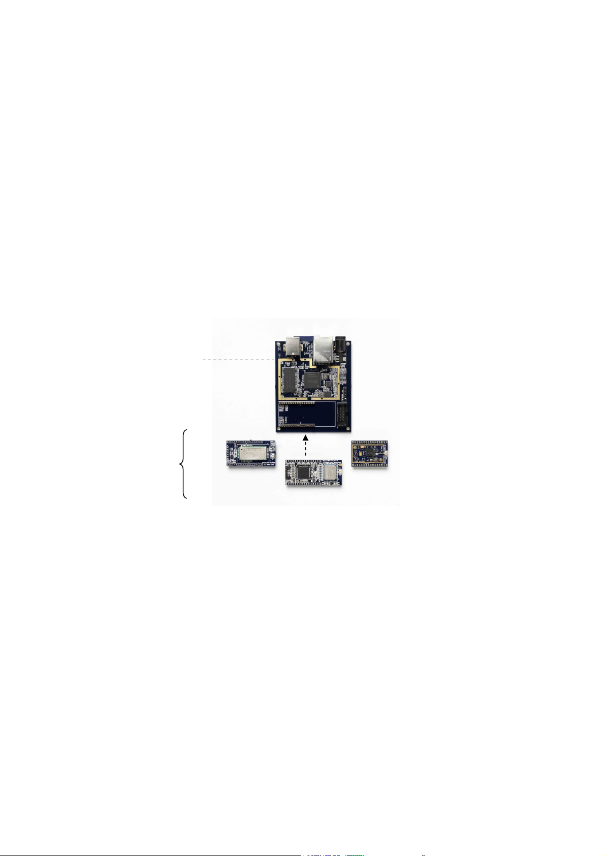
The Gateway Evaluation kit is a development environment for wired-to-wireless connectivity
applications. The kit includes the following:
• Gateway board (motherboard) with USB & Ethernet connectors
• A radio module (daughter board) – which is radio-standard-specific
• Embedded software development suite, CyanIDE 2
• Debug adaptor (to provide the MCU debug connection for the CyanIDE 2 debugger)
The development kit provides a fast-start for OEMs wishing to implement and integrate USB,
Ethernet, and other wired communication functionality, into their products.
Different or new radio standards can be accommodated by changing the radio daughter board
and a firmware update.
CyanIDE 2 includes radio-specific software peripherals to enable rapid switching over to
different radio standards (for example, from Wireless MBus to ZigBee).
Gateway Board
Radio Modules
Wireless
M-BUS
CyNet3
ZigBee
Module versions of the evaluation kit, which plug into the OEM’s proprietary motherboard, are
available for requirements where further access to microcontroller device pins is needed.
High-volume OEMs wishing to integrate and modify the gateway board circuitry (for example, to
support multiple/emerging/proprietary radio standards) should contact Cyan for a manufacturing
package.
Cyan supplies microcontrollers, board-level gateway products (with RF according to the
wireless standard), s/w protocol stacks, and low-cost development tools/boards.
11 March 2009 Cyan Technology Ltd. Page 6
Page 7

Gateway Evaluation Kit for ZigBee - Getting Started Guide Version 1.1
2 PC and Cable Requirements
These notes guide first-time users through:
• Installation of CyanIDE 2.
• Connecting-up the gateway board, the eICE debug adaptor and the PC.
• Selecting an example project, building and downloading the application, and running
the demonstration.
CyanIDE 2 installs on a PC running Windows XP or Vista. The PC must have the following
available:
• 1GB of free disk space.
• CD-ROM drive.
• One Ethernet port (for use in example projects).
• Two USB ports (one for connecting the eICE debug adaptor, one for use in example
projects).
• A serial port or an additional USB port with a USB-serial converter cable (to display
“printf” status/debug messages from example projects) – ideally one per each gateway
board being used.
The use of a powered USB hub is suggested.
The PC should also have installed:
• Internet Browser.
• Adobe Reader.
• Terminal Emulator program.
• WinZip (or similar, to unzip files).
In order to run the example projects, the following may also be required:
• 5V PSU. (Optional, if the supply from the eICE debug adaptor, itself USB-powered, is
not sufficient. This may exhibit itself by a failure of the debugger at download time.)
• Ethernet cable (for gateway board to PC connection).
• USB flash drive (for the embedded web server projects).
• USB adaptor cable to allow the USB flash drive to be connected to the USB peripheral
connector on the gateway board.
11 March 2009 Cyan Technology Ltd. Page 7
Page 8

Gateway Evaluation Kit for ZigBee - Getting Started Guide Version 1.1
3 Installation of CyanIDE 2
3.1 CyanIDE 2 Version Notes
The Gateway Evaluation kit requires CyanIDE 2.1.1 or a later version. CyanIDE is supplied on
the CD included in the kit.
The CD contains the complete suite of software development tools for Cyan microcontrollers
and full documentation on the development kit boards.
Cyan does not release patches but releases complete updated versions of CyanIDE. These are
made available for download on the Cyan website. Developers should regularly check the Cyan
web site for the latest version.
3.2 Installation Notes
Insert the CD in the drive and it should autoplay.
If it does not, then go to My Computer, right-click on Devices with Removable Storage and
select Autoplay.
Follow the prompts to install CyanIDE.
(A previous installation of CyanIDE 1.4 can co-exist with CyanIDE 2.1.1.
A previous installation of an earlier version of CyanIDE 2 can co-exist with CyanIDE 2.1.1.)
IMPORTANT: Close all other applications before starting set-up.
11 March 2009 Cyan Technology Ltd. Page 8
Page 9

Gateway Evaluation Kit for ZigBee - Getting Started Guide Version 1.1
4 Connecting-Up
The target system is shown, in diagram form, for reference at the end of this section. The
diagrams may be useful when following the instructions below.
4.1 Target System Connections
Connect-up as follows:
1. Fit the radio module to the gateway board.
a. The radio module plugs into the two 16-pin headers.
b. The antenna connector is adjacent to the 10-way debug connector.
2. Connect the eICE adaptor to the gateway board using the ribbon cable.
3. Connect the eICE adaptor to the USB cable (for connecting to the PC) – DO NOT
CONNECT THE USB CABLE TO THE PC AT THIS TIME.
4. If an example project is to be run, the “printf” status/debug messages (displayed using
a terminal emulator) are required. Connect a 3-way serial cable to J10 on the gateway
board:
a. If using the 3-way cable from the Cyan Cable kit, pin 1 is indicated by the arrow
on the moulding of the connector. Pin 1 on the board header is nearest the
debug connector – see diagram below.
b. This cable should be connected to the PC serial port, or to a USB-Serial
converter (if the PC has USB but no serial ports).
(The COM port number should be noted for setting-up the terminal emulator;
to check the port number, at the control panel, select:
System->Hardware->Device Manager->Ports (COM&LPT) )
5. Connect the antenna to the radio module.
6. Check all connections are made, then connect the USB cable from the eICE adaptor to
the PC. This powers-up the target system.
4.2 Target Power
The gateway board is powered from the eICE debug adaptor, which in turn is powered from the
PC USB port.
If the supply from the eICE adaptor is not sufficient to drive the gateway board, an external 5V
power supply may be used. Simply connect the external supply to the d.c. jack on the gateway
board. The on-board circuitry includes blocking diodes which eliminate the need for supply
changeover links.
If the eICE adaptor is connected to the PC via a USB hub and does not connect reliably to the
target gateway, then check the power supply voltage. A USB hub powered by a separate PSU
is recommended.
Note: the module version of the gateway board, which plugs into the customer’s main board,
requires a 3.3V supply connected through the module daughter board pin headers.
A “gateway module” has pin headers on the underside to allow it to plug into a motherboard.
A “gateway board” is for stand-alone use.
11 March 2009 Cyan Technology Ltd. Page 9
Page 10
Gateway Evaluation Kit for ZigBee - Getting Started Guide Version 1.1
p
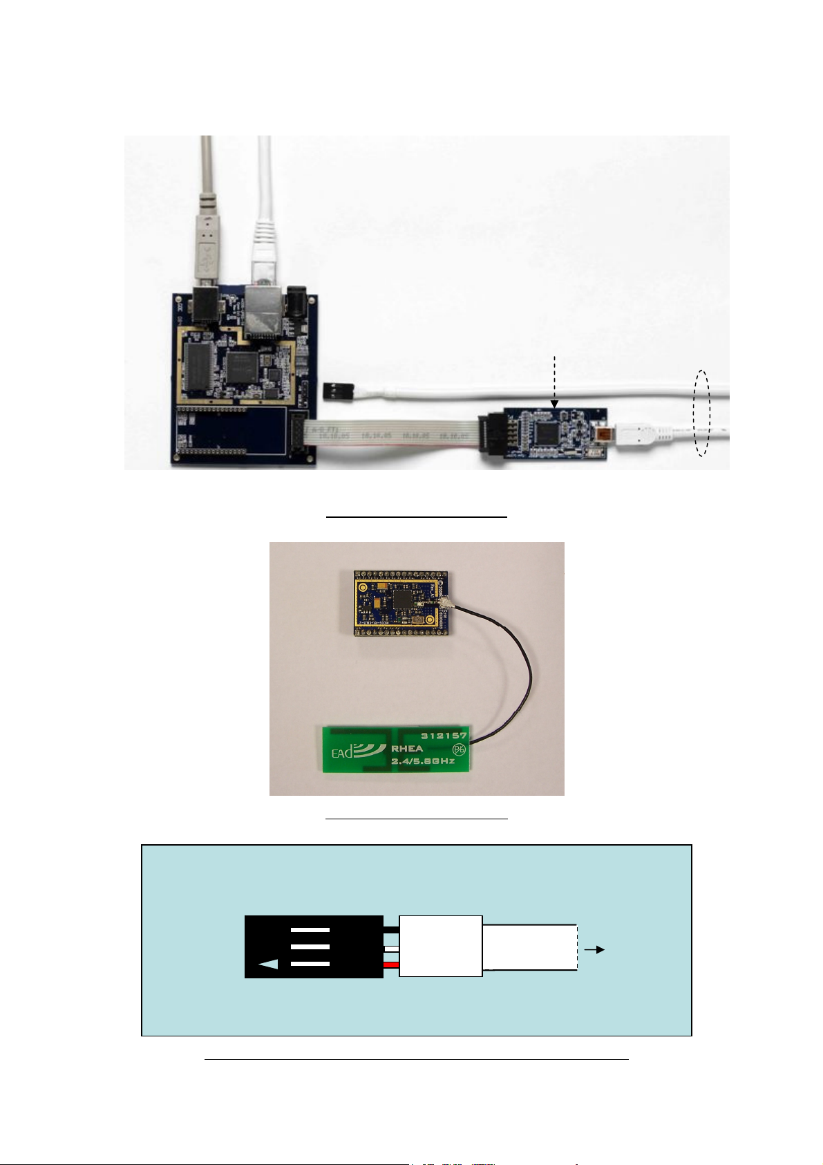
4.3 Connection Overview Diagrams
Radio
Module
Socket
USB
Ethernet
3-way Serial Lead
(for “printf” status
messages/ debugging)
System Connection Overview
eICE Adaptor
(also known
as “dongle”)
To
PC
Pin3
Pin1
ZigBee
Radio
Module
Module / Antenna Connection
Shrink
wra
To PC
3-way Serial Cable (as in Cyan Cable kit) – Connector Close-up View
11 March 2009 Cyan Technology Ltd. Page 10
Page 11

Gateway Evaluation Kit for ZigBee - Getting Started Guide Version 1.1
5 Summary of Example Projects
Built into CyanIDE 2 are example projects for the Gateway, including:
• Basic Ethernet and USB demo projects.
• USB peripheral, host and mass storage applications.
• TCP/IP examples using the open source uIP stack, including:
o Embedded webserver, FTP, FAT filing system.
• Cyan Cy-Net 3, a wireless mesh network protocol, using an ISM-band Micrel
MICRF6x0 RF transceiver (requires an mCOG-RF-1X-M1 of the selected frequency).
• Wireless M-Bus, an industrial and utility metering radio protocol, using a Radiocrafts
RC1180 module (requires an mCOG-RF-RCWMB).
• ZigBee utility metering example using an Ember EM260 device (requires an mCOG-
RF-EMZ1-2).
Note: The Cyan mCOG-xxx radio modules are listed on www.cyantechnology.com
.
11 March 2009 Cyan Technology Ltd. Page 11
Page 12
Gateway Evaluation Kit for ZigBee - Getting Started Guide Version 1.1
6 ZigBee Example Projects
6.1 Overview
6.1.1 Radio Module
It is assumed a ZigBee daughter board, an mCOG-RF-EMZ1-2 (using an Ember EM260), is
fitted to the gateway board.
6.1.2 Projects Summary
CyanIDE 2 includes the following example projects:
• Concentrator – the gateway receives data over-the-air via the EM260
• Meter – the gateway sends data over-the-air via the EM260
• Gateway – data received via the EM260 is combined with an embedded web page and
served via Ethernet and TCP/IP to a PC browser
• Sink Demo – the gateway acts as a concentrator and receives over-the-air data from
an Ember EM260 SPI/UART Breakout board fitted with an EM260 radio daughter
board.
To demonstrate the Concentrator, Meter and Gateway projects requires two Cyan Gateway
boards.
Further details on the Ember boards are in Appendix B.
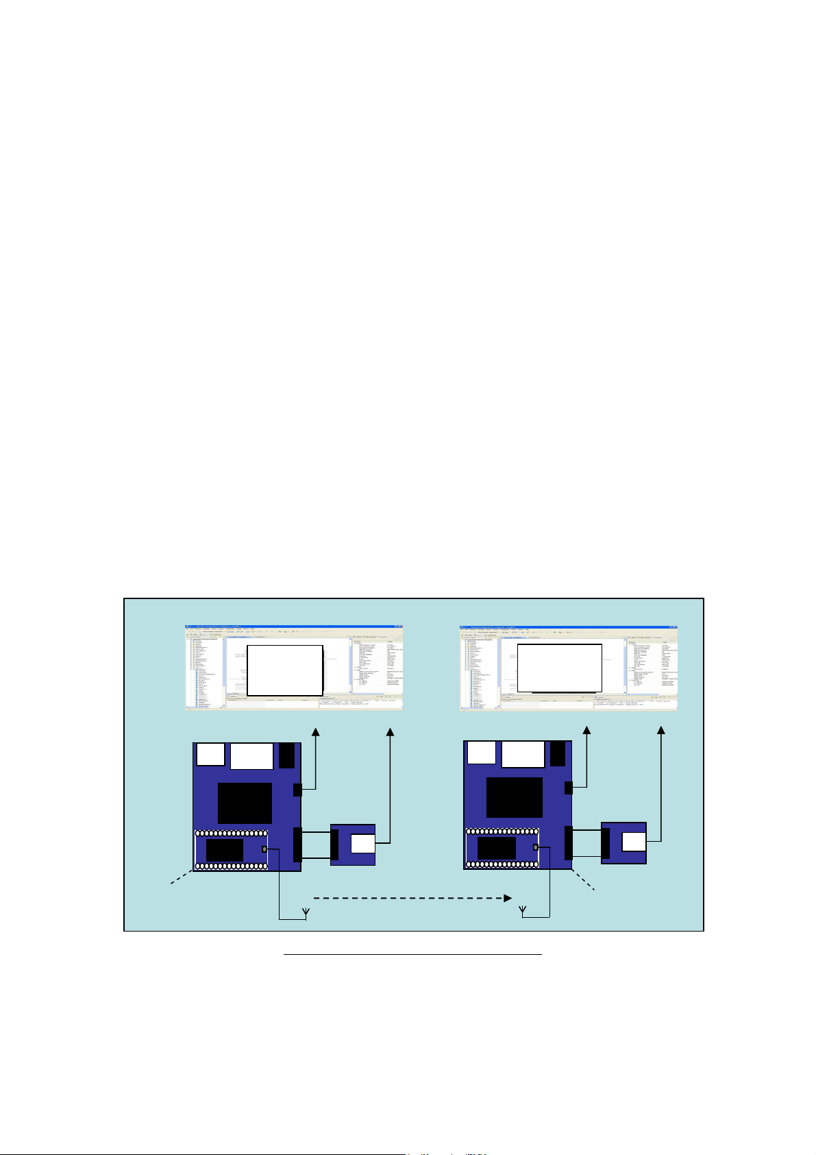
6.1.3 Using Two Gateways - System Overview
The system comprises:
USB
EM260
Ethernet
eCOG
MCU
CyanIDE2
Meter
Project
serial
eICE
Adapto r 1
USB
EM260
Ethernet
eCOG
MCU
CyanIDE2
Concentrator
Project
serial
eICE
Adapto r 2
Gateway 1
ZigBee
Gateway 2
Gateway 1 linked via ZigBee to Gateway 2
6.1.4 Antenna Fitting Note
It is recommended appropriate antennas are fitted to both mCOG modules.
If no antennas are fitted, then the boards will have to be positioned very close together but a
working system is not guaranteed.
11 March 2009 Cyan Technology Ltd. Page 12
Page 13

Gateway Evaluation Kit for ZigBee - Getting Started Guide Version 1.1
7 Meter and Concentrator Example Projects
7.1 Overview
It is assumed there are two gateway boards and two eICE adaptors.
• Gateway1 is used as a meter.
• Gateway2 is used in two ways, firstly as a concentrator (to receive data over the
ZigBee link), and secondly as a gateway, to receive the data, and to serve an
embedded web page (from internal flash memory) using Ethernet and TCP/IP to a web
browser running on a PC.
CyanIDE 2 is invoked and connected to gateway1 using eICE adaptor1. (eICE adaptor2 is not
connected to the PC at this time.)
eICE adaptor2 is then connected to the PC. CyanIDE 2 is invoked for a second time such that a
separate instance is running on the PC. It is connected to gateway2 using eICE adaptor2.
(This order is the simplest mechanism for ensuring the correct instance of CyanIDE 2 is
connected to the correct gateway board.)
7.2 Steps / Procedure
The steps for the meter and concentrator projects are:
• Invoke CyanIDE 2.
• Connect only the eICE adaptors and update if required.
Their IDs must be different.
The firmware must be the latest version.
• Connect up gateway1 and eICE adaptor1.
Ensure gateway2 and eICE adaptor2 are disconnected from the PC.
• Create and build the CYDF ESZP EM260 meter project.
• Using the Configurator, note the serial port configuration for the terminal emulator.
• Invoke the terminal emulator and configure.
• Download (to gateway1) and run the meter project to ‘main’ (where execution breaks).
• Resume execution and confirm project title is displayed by the terminal emulator.
• Suspend execution.
At this point gateway1 is ready to act as a meter emulator. Now for gateway2.
• Connect up gateway2 and eICE adaptor2
• Invoke CyanIDE 2 to obtain two instances running on the PC
• Create and build the CYDF ESZP EM260 concentrator project
• Using the Configurator, note the serial port configuration for the terminal emulator
• Invoke the terminal emulator, to obtain two instances running on the PC, and configure
• Download (to gateway2) and run the concentrator project to ‘main’ (where execution
breaks)
• Resume execution and confirm project title is displayed by the second terminal
emulator instance
• At this point, gateway2 is up-and-running
• Restart the meter project on gateway1 – the gateway2 terminal emulator should
display data from gateway1.
11 March 2009 Cyan Technology Ltd. Page 13
Page 14

Gateway Evaluation Kit for ZigBee - Getting Started Guide Version 1.1
7.3 eICE Adaptors – ID and Firmware Version check
Connect eICE adaptor 1 to the PC. Ensure only one eICE adaptor is connected to the PC. It
should not be connected to a gateway board at this time.
Invoke CyanIDE 2 - from the shortcut on the desktop or from the program list.
At the prompt to enter a workspace, use the default (or enter a preferred alternative
workspace).
Click OK to bring up the Welcome screen. This is only displayed automatically on the first
invocation. (On subsequent invocations, it can be accessed from the Help menu.)
Close the Welcome window - click on X in the Welcome tab. (The developer is encouraged to
explore the Overview, First Steps or Web Resources, by clicking on the central icons).
11 March 2009 Cyan Technology Ltd. Page 14
Page 15

Gateway Evaluation Kit for ZigBee - Getting Started Guide Version 1.1
The Workbench is displayed, typically as shown below.
The Workbench presents a perspective (simply a group of views) to the user. Note there are
3 perspectives regularly used, Configurator, C/C++, and Debug. These are used later when
building the projects.
Select the Debug Interface Manager….
And click on Refresh
11 March 2009 Cyan Technology Ltd. Page 15
Page 16

Gateway Evaluation Kit for ZigBee - Getting Started Guide Version 1.1
A typical resulting display is shown below.
If either the Loader Version or the Application Version are less than the available versions,
click on Reprogram to update the firmware in the adaptor.
Note the Serial Number and Identifier.
Remove the USB cable from adaptor1 and fit to adaptor2.
Click on Refresh.
If the Serial Number and Identifier are the same as the first adaptor, edit the values and
Reprogram.
Note: If the Debug Interface Manager reports an error, then close the Manager and re-try.
(Appendix A describes the Debug Interface Manager in more detail.)
Disconnect the eICE adaptor from the USB cable.
Close and Exit from CyanIDE 2.
11 March 2009 Cyan Technology Ltd. Page 16
Page 17

Gateway Evaluation Kit for ZigBee - Getting Started Guide Version 1.1
7.4 Create and Build the Meter Example Project 1
7.4.1 Connect-up and Invoke CyanIDE
Ensure gateway1 is connected to the PC as shown in section4.
Connect eICE adaptor1 to gateway1 (using the ribbon cable) and connect to the PC. (Ensure
eICE adaptor2 is disconnected from the PC).
Invoke CyanIDE 2.1.1 (or later version) and select a workspace to be used only for the meter
project, e.g. workspace211meter.
7.4.2 Create the Meter Project
Select ‘File -> New -> Cyan eCOG Executable Project’
This opens a window to create a new project.
11 March 2009 Cyan Technology Ltd. Page 17
Page 18

Gateway Evaluation Kit for ZigBee - Getting Started Guide Version 1.1
Enter a meaningful project name, for example “ZigBee-meter-project”, select the USB Ethernet
Gateway as the development board type and the CYDF EZSP EM260 meter project
template….
.. then click “Finish”.
Normally the Configurator perspective is then displayed, depending on the previous
workspace window arrangement. (If not, then it can be opened using ‘Window->Open
Perspective->….’).
The eCOG1X canvas should be displayed – if not, then double-click on the .cyanidecfg file in
the Project Explorer view.
11 March 2009 Cyan Technology Ltd. Page 18
Page 19

Gateway Evaluation Kit for ZigBee - Getting Started Guide Version 1.1
Using Window->Open Perspective->…., open the C/C++ Perspective and the Debug
Perspective.
7.4.3 Build the Project
Select the C/C++ Perspective – the following should be displayed.
In the Project Explorer view, right-click on the active project and select build project.
The build progress is displayed in the Console view (lower right hand corner).
11 March 2009 Cyan Technology Ltd. Page 19
Page 20

Gateway Evaluation Kit for ZigBee - Getting Started Guide Version 1.1
7.4.4 Determine the Serial Configuration
Return to the Configurator Perspective.
Click on UART1B in the canvas – this is used to transmit any output from printf statements to
the terminal emulator.
Note the serial port configuration displayed in the Property view (used to set-up the terminal
emulator).
In this example, the configuration is 19230 baud, 8 data bits, no parity, 1 stop bit.
7.4.5 Invoke the Terminal Emulator
Invoke the terminal emulator program.
Ensure the gateway 3-pin serial cable is connected to the selected COM port.
(COM port numbers on the PC can be checked using the Device Manager - reached via the
control panel->System->Hardware->Device Manager-> Ports (COM & LPT) )
Ensure the serial configuration of the terminal emulator is set to the configuration determined
from the Configurator.
11 March 2009 Cyan Technology Ltd. Page 20
Page 21

Gateway Evaluation Kit for ZigBee - Getting Started Guide Version 1.1
7.4.6 Download and Run the Meter Project to ‘main’
Return to the C/C++ Perspective.
The next step is the Debug operation, which combines
• Download to target.
• Programming of flash memory on the target eCOG microcontroller.
• Invocation of the debugger (GDB).
Right click on the active project and select “Debug As->Cyan eCOG Debug Interface”.
CyanIDE connects to the target board via the eICE adaptor, downloads the .elf file, …
… executes the program to ‘main’, and then breaks.
11 March 2009 Cyan Technology Ltd. Page 21
Page 22

Gateway Evaluation Kit for ZigBee - Getting Started Guide Version 1.1
7.4.7 Run to Output Project Title
Select Resume.
Observe the project title on the terminal emulator display .
Suspend execution of the program (click on the double vertical yellow bars).
11 March 2009 Cyan Technology Ltd. Page 22
Page 23

Gateway Evaluation Kit for ZigBee - Getting Started Guide Version 1.1
7.5 Create and Build the Concentrator Example Project 2
7.5.1 Connect-up, and Invoke CyanIDE 2
Ensure gateway2 is connected to the PC as shown in section4.
Connect eICE adaptor2 to gateway2 (using the ribbon cable) and connect to the PC.
Invoke CyanIDE 2 and select a workspace to be used only for the concentrator project, for
example “workspace211concentrator”.
7.5.2 Create the Concentrator Project
Select ‘File -> New -> Cyan eCOG Executable Project’
This opens a window to create a new project.
11 March 2009 Cyan Technology Ltd. Page 23
Page 24

Gateway Evaluation Kit for ZigBee - Getting Started Guide Version 1.1
Enter a meaningful project name, for example “ZigBee-concentrator-project”, select the USB
Ethernet Gateway as the development board type and the CYDF EZSP EM260 concentrator
project template…
.. then click “Finish”.
The Configurator perspective is displayed. (If not, then it can be opened using ‘Window->
Open Perspective->.’).
The eCOG1X canvas is also displayed – if not, then double-click on the .cyanidecfg file in the
Project Explorer view.
7.5.3 Build the Project
Select the C/C++ Perspective.
In the Project Explorer view, right-click on the active project and select build project.
The build progress is displayed in the Console view (lower right hand corner).
11 March 2009 Cyan Technology Ltd. Page 24
Page 25

Gateway Evaluation Kit for ZigBee - Getting Started Guide Version 1.1
7.5.4 Determine the Serial Configuration
Use the same procedure as used for the meter project:
• Return to the Configurator Perspective.
• Click on UART1B in the canvas – this is used to transmit printf statements to the
terminal emulator
Note the serial port configuration displayed in the Property view. In this example, the
configuration is 19230 baud, 8 data bits, no parity, 1 stop bit.
7.5.5 Invoke the Terminal Emulator
Invoke the terminal emulator program such that a second separate instance is running.
Ensure the gateway2 3-pin serial cable is connected to the selected COM port.
(COM port numbers on the PC can be checked using the Device Manager - reached via the
control panel->System->Hardware->Device Manager-> Ports (COM & LPT) )
Ensure the serial configuration of the terminal emulator is set to the configuration determined
from the Configurator.
7.5.6 Download and Run the Concentrator Project to ‘main’
Return to the C/C++ Perspective.
Right click on the active project and select “Debug As -> Cyan eCOG Debug Interface”.
CyanIDE connects to the target board via the eICE adaptor, downloads the .elf file, executes
the program to ‘main’, and then breaks.
11 March 2009 Cyan Technology Ltd. Page 25
Page 26

Gateway Evaluation Kit for ZigBee - Getting Started Guide Version 1.1
7.5.7 Run to Output Project Title
Select Resume.
Observe the project title on the terminal emulator display.
Suspend execution of the program (click on the double vertical yellow bars).
At this point, both the meter project and the concentrator projects are suspended.
11 March 2009 Cyan Technology Ltd. Page 26
Page 27

Gateway Evaluation Kit for ZigBee - Getting Started Guide Version 1.1
7.6 Resume the Projects
Return to the meter project and in the CyanIDE 2 Debug Perspective click on Restart.
The program executes and breaks at ‘main’. Select Resume.
Return to the concentrator project and in the CyanIDE 2 Debug Perspective click on Restart.
The program executes and breaks at ‘main’. Select Resume.
The terminal emulator for the meter project displays transmitted data and status information.
The terminal emulator for the concentrator project displays received data and status
information.
The PC screen display is typically:
11 March 2009 Cyan Technology Ltd. Page 27
Page 28

Gateway Evaluation Kit for ZigBee - Getting Started Guide Version 1.1
7.7 Terminate and Close
If the third example project, the gateway project (which receives data, and serves an embedded
web page to a browser running on a PC) is now to be run.
• Suspend the meter project (in the debug view, select the double-yellow-bar button).
• Terminate and close the concentrator project.
If no further projects are to be run, terminate both projects.
Terminate a project using Terminate (red square button) in the Debug View.
Then right-click on the terminated .elf file and select Remove All Terminated.
11 March 2009 Cyan Technology Ltd. Page 28
Page 29

Gateway Evaluation Kit for ZigBee - Getting Started Guide Version 1.1
Return to the C/C++ Perspective, right-click on the project and select Delete.
Ensure the project contents are deleted.
This completes the running of the Concentrator example.
11 March 2009 Cyan Technology Ltd. Page 29
Page 30

Gateway Evaluation Kit for ZigBee - Getting Started Guide Version 1.1
8 Gateway Embedded Web Server Example Project
8.1 Overview and Assumptions
In this project, one Cyan Gateway acts as a meter emulator and transmits data; a second Cyan
Gateway acts as a meter concentrator, receives and outputs the data to the terminal emulator.
The gateway also serves an embedded web page to a browser over Ethernet using fixed IP
addresses. This web page displays data received from the meter emulator gateway.
It is assumed:
• The user has already run the meter emulator and meter concentrator example projects
above and is familiar with creating and building CyanIDE projects.
• The eICE adaptors have unique IDs and the latest firmware.
• CyanIDE 2 is running the meter emulator example project – and is currently
suspended.
The steps to run the gateway project are:
• Ensure eICE adaptor2 is connected to the PC.
• Ensure gateway2 is connected, including the Ethernet cable to the PC.
• Create and build the gateway project.
• Select the Configurator Perspective.
• Note the IP address settings (for the PC and for the browser).
• Note the serial port settings (for the terminal emulator).
• Ensure the terminal emulator is configured and running.
• Download onto gateway2, run to ‘main’ and resume execution when it pauses at the
first breakpoint.
• Invoke the browser, enter the IP address and display the embedded web page.
• Resume code execution on gateway board 1 to transmit data.
• Refresh the browser display to get the data from board 1 displayed.
8.2 Create and Build the Gateway Project
Ensure eICE adaptor2 is connected to the PC.
Ensure gateway2 is connected-up, including the Ethernet cable to the PC.
Invoke a second instance of CyanIDE 2.1.1.
Select a workspace for this project only, for example “workspace211-gateway”.
Select ‘File->New->Cyan eCOG Executable Project’.
Enter a project name (or use the default), select the USB Ethernet Gateway as the
development board type and the CYDF EZSP EM260 Gateway project template.
The Configurator perspective should then be displayed. (If not, then it can be opened using
‘Window->Open Perspective->.’). Also open the C/C++ and Debug perspectives.
Build the project.
11 March 2009 Cyan Technology Ltd. Page 30
Page 31

Gateway Evaluation Kit for ZigBee - Getting Started Guide Version 1.1
8.3 PC Network Configuration
Select the Configurator perspective. Ensure the eCOG1X canvas is displayed. (If not, in the
Project Explorer view, double-click on the .cyanide.cfg file.)
Click on the uIP 1.0 software peripheral, and its properties are displayed in the Property view
(upper right).
The IP Address (192.168.1.2) is the IP address of the gateway.
The Default Router Address (192.168.1.1) is the address to be used for the PC network
configuration.
Now:
• In the PC’s Control Panel…
• ..select Network Connections.
• Right-click on Local Area Connection to display the Properties…
• … and scroll down to Internet Protocol and click on it.
• Select Properties…
• … then Use the following IP address to fix the IP address
• … and set an appropriate IP address (refer to the CyanIDE 2 Property View).
(The PC should be set to the default router address; in the above screen shot this is
192.168.1.1)
• … and also set the subnet mask to that shown in the Property view
• … and click ok
• … and close Local Area Connection Properties
IMPORTANT: For the new network settings to take effect, you must perform the click ok and
close steps above.
11 March 2009 Cyan Technology Ltd. Page 31
Page 32

Gateway Evaluation Kit for ZigBee - Getting Started Guide Version 1.1
8.4 Terminal Emulator
In the Configurator Perspective, click on the UART1B peripheral. Its properties are displayed
in the Property view (upper right). In this screen shot, the baud rate is 9600 baud.
Ensure the terminal emulator is connected to gateway2.
8.5 Download and Execute
Return to the CyanIDE C/C++ perspective.
Download the project to gateway2, allow the program to execute and break at ‘main’. (Right
click on the active project and select “Debug As -> Cyan eCOG Debug Interface”)
Click Resume; the terminal emulator typically displays:
8.6 Run the Meter Emulator Project
Ensure gateway board 1 is running the Meter Emulator project. If the program is suspended,
click Resume in the Debug Perspective.
Typical terminal emulator displays are shown below, with the gateway1/meter project output
shown on the left, and the gateway2/gateway project output shown on the right.
11 March 2009 Cyan Technology Ltd. Page 32
Page 33

Gateway Evaluation Kit for ZigBee - Getting Started Guide Version 1.1
8.7 Display Web page
At the PC, run Internet Explorer or any other web browser, using the IP address of the
gateway board 2 (192.168.1.2 in the example shown in the screen shots), and the web page is
displayed. The top left meter displays data sent by the meter project.
Wait for a short period (a few seconds) and then click refresh on the browser to update the
meter readings.
This completes the gateway embedded web server project.
8.8 Terminate and Close
Select the Debug Perspective.
Terminate the project (using the red square button).
Right-click on the terminated .elf file and select Remove All Terminated.
Return to the C/C++ Perspective, right-click on the project and select Delete.
Ensure the project contents are deleted.
Repeat for the meter project.
11 March 2009 Cyan Technology Ltd. Page 33
Page 34

Gateway Evaluation Kit for ZigBee - Getting Started Guide Version 1.1
8.9 Changing the Web Page Data
The subfolder <httpd-fs> of this project contains the HTML files that are served by the http web
server. These HTML files are included in the project as fixed binary data, stored as constant
data in the eCOG1X internal flash memory. To change the web page content, first modify the
HTML source files as required. Then use the PERL script DOSMakeFS.pl (distributed with this
example application) to convert the HTML source files into binary data, stored in the C source
file httpd-fsdata.c.
To find out the size of the static file system data for each web page, build the project and open
the generated ELF file and search for a symbol corresponding to one of the html files, for
example data_404_html. The following shows an example:
0000045e l O .ecog1.const 000000ab data_404_html
This indicates that the data_404_html web page data occupies 0x00ab bytes in the constant
data area of internal flash.
A suitable PERL script interpreter is ActivePERL, which is available as a free download from
ActiveState at <www.activestate.com> for AIX, HP-UX, Linux, Mac OS X, Solaris and Windows.
11 March 2009 Cyan Technology Ltd. Page 34
Page 35

Gateway Evaluation Kit for ZigBee - Getting Started Guide Version 1.1
US
ptor
9 Sink Example Project
9.1 System Overview and Assumptions
In this project, an Ember EM260 Breakout board acts a meter emulator and transmits data; a
Cyan Gateway acts as a meter concentrator and receives and outputs the data to the terminal
emulator.
CyanIDE2
Sink Demo
Project
USB
To PC
B
Ethernet
Prototyping
Area
EM260
eCOG
EM260
serial
eICE
ada
USB
Ember EM260
SPI/UART
Breakout Board
ZigBee
Gateway
Ember EM260 (acting as a Meter) linked via ZigBee to Gateway (acting as a Concentrator)
(See Appendix B for further information on the Ember board.)
It is assumed:
• The user has already run the meter emulator and meter concentrator example projects
above and is familiar with creating and building CyanIDE projects.
• The user has available an Ember EM260 SPI/UART Breakout board fitted with an
Ember EM260 SPI/UART radio communication module (RCM).
The steps to run the sink project are:
• Ensure only one gateway board and eICE adaptor are connected to the PC.
• Create and build the sink project.
• Select the Configurator Perspective.
• Note the serial port settings (for the terminal emulator).
• Ensure the terminal emulator is configured and running.
• Download onto gateway, run to ‘main’ and resume execution when it pauses at the first
breakpoint.
• Connect a USB cable to the PC and to the Ember Breakout board.
• Wait for a short period (this may be 30 seconds approx).
• Data from the Ember Breakout board is received by the gateway and displayed on the
terminal screen.
11 March 2009 Cyan Technology Ltd. Page 35
Page 36

Gateway Evaluation Kit for ZigBee - Getting Started Guide Version 1.1
9.2 Create and Build the Sink Project
Ensure an eICE adaptor is connected to the gateway and to the PC.
Invoke CyanIDE 2.1.1.
Select a workspace for this project only, for example “workspace211sinkdemo”.
Select ‘File->New->Cyan eCOG Executable Project’.
Enter a project name (or use the default), select the USB Ethernet Gateway as the
development board type and the CYDF EZSP EM260 Sink demo project template.
The Configurator perspective is then displayed. (If not, then it can be opened using ‘Window->
Open Perspective-> ….’). Also open the C/C++ and Debug perspectives.
Build the project.
9.3 Terminal Emulator
In the Configurator Perspective, click on the UART1B peripheral. Its properties are displayed
in the Property view, (upper right). In this screen shot, the baud rate is 19k2baud.
Ensure the terminal emulator is connected to the gateway.
11 March 2009 Cyan Technology Ltd. Page 36
Page 37

Gateway Evaluation Kit for ZigBee - Getting Started Guide Version 1.1
9.4 Download and Execute
Return to the CyanIDE C/C++ perspective.
Download the project to gateway2, allow the program to execute and break at ‘main’. (Right
click on the active project and select “Debug As -> Cyan eCOG Debug Interface”)
Click Resume, the terminal emulator typically displays:
9.5 Connect the Ember EM260 SPI/UART Breakout board
Connect the Ember Breakout board to the PC using the USB cable – this will power-up the
board.
Wait a few seconds (approximately 30 seconds).
Data received from the Breakout board is received by the gateway and displayed on the
terminal emulator.
This ends the sink demo project.
9.6 Terminate and Close
Select the Debug Perspective.
Terminate the project (using the red square button).
Right-click on the terminated .elf file and select Remove All Terminated.
Return to the C/C++ Perspective, right-click on the project and select Delete.
Ensure the project contents are deleted.
11 March 2009 Cyan Technology Ltd. Page 37
Page 38

Gateway Evaluation Kit for ZigBee - Getting Started Guide Version 1.1
Appendix A eICE Adaptor (Dongle) Update / ID Setting
The firmware of the eICE adaptor is updated using the Debug Interface Manager in CyanIDE 2.
Invoke CyanIDE 2 and, in any perspective, select Debug->Debug Interface Manager.
The Debug Interface Manager, when opened, appears as below.
Use this button, if you have more than one eICE
adaptor connected to your PC, to identify the
connected adaptors.
Use this button to read the status of the
connected adaptor
Use this button to download and update the
firmware version
If you have only one eICE adaptor connected, then leave auto as the entry in Target Debug
Interface and click on Refresh or Reprogram as required.
11 March 2009 Cyan Technology Ltd. Page 38
Page 39

Gateway Evaluation Kit for ZigBee - Getting Started Guide Version 1.1
If you have more than one eICE adaptor connected, then selecting
Discovery->Run Discovery Now typically gives:
This can be copied……
……and pasted here. Clicking OK
will return you to the previous screen
where the Identifier and Serial
Number may be changed, if required
IMPORTANT: If you have two or more eICE adaptors both set to the same Identifier and Serial
Number (for example, set to the shipped default), then an error is reported. Simply
• Disconnect all adaptors but one.
• Run the discovery command to get the current Identifier and Serial Number.
• Return to the Debug Interface Manager window.
• Type in a unique Identifier and Serial Number.
• Click on Reprogram.
11 March 2009 Cyan Technology Ltd. Page 39
Page 40

Gateway Evaluation Kit for ZigBee - Getting Started Guide Version 1.1
Appendix B Ember EM260 Breakout Board
The example sink demo project was developed using:
• Ember EM260 SPI/UART radio
communication module
(710-0401-000)
Fitted to:
• Ember EM260 SPI/UART Breakout
board (710-0471-000)
The EM260 SPI/UART breakout board switch settings:
• SW1 set to ‘SPI’
• SW2 set to ‘USB’
The breakout board is powered when the USB port is connected to a PC.
The board operates in a stand-alone mode and starts transmitting data on being powered-up.
Note: Ember supplies different variants of breakout board. The breakout boards are also
subject to revision. Assuming an EM260 device is used, it is expected that other variants and
versions of the breakout boards may be used without issue, but no warranties as to correct
project operation can be provided and support may be limited.
Document References:
• EM260 SPI/ UART Breakout Board Technical Spec, document number 120-2006-000.
Further information is available on:
http://www.ember.com/products_documentation.html
11 March 2009 Cyan Technology Ltd. Page 40
 Loading...