

Page 1
P/N IM-360 Rev. A
2018 Tyco Fire & Security GmbH
1
Smoke/CO/Heat Detector with
Transmitter Models 360/370
Description:
The Models 360 and 370 are multi-criteria type detectors with an integral transmitter and
sounder. The Model 360 is a smoke/heat detector and the Model 370 is a smoke/heat/CO
detector. Both models are configurable at the detector for single or multiple detection modes,
sounder function and tandem operation. The detectors are fully supervised for alarm and
trouble conditions as listed in this manual. The detectors are powered by a two independently
monitored 3 volt lithium batteries as li sted under the specifications section of this manual and
the label on the product. The Models 360/370 are UL listed and intended to be used with
CWSI Fire Alarm Control Panels. Refer to the FACP manual for compatibility details and the
specification section of this manual for compliance listings.
IMPORTANT: The detectors must be tested and maintained regularly following NFPA 72
requirements. At a minimum, cleaning should be performed annually.
Configuration and Programming:
The 360/370 must be configured and enrolled into the FACP before installation.
NOTE: The Models 360/370 will not report Alarms, Supervisory or trouble signals
unless correctly configured and enrolled into a CWSI Fire Alarm Control Panel.
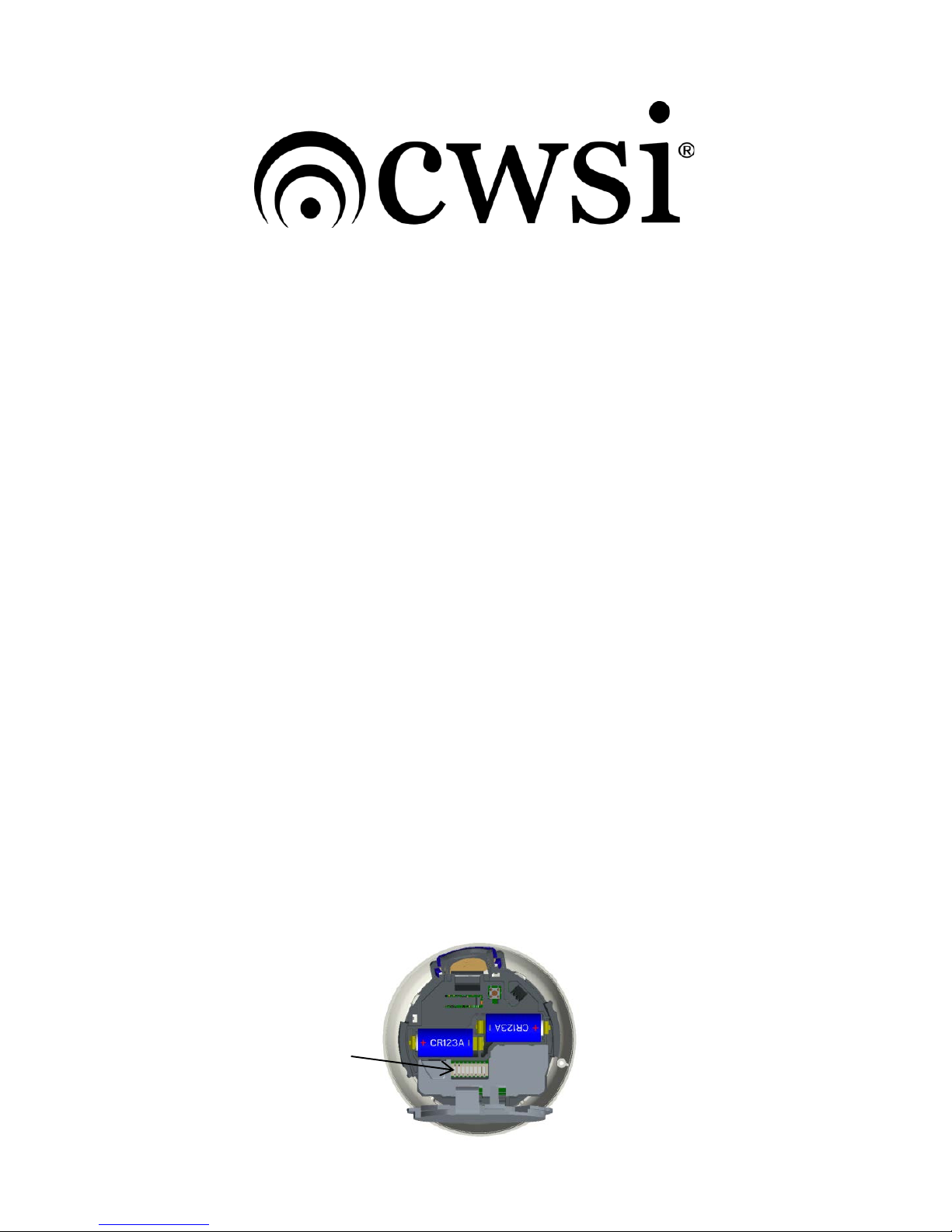
Both Models 360 and 370 contain an 8 position dip switch located under the battery
compartment cover as shown in Figure 1. To access the switch first twist and remove the
mounting plate then lift open the hinged battery cover.
NOTE: Configuration dip switches must be set to the desired configuration BEFORE
installing the batteries. The detectors will not respond to switch changes after power
up. If the detector configuration needs to be changed, remove the batteries, wait 20
seconds, set the switches as desired and reinstall the batteries.
The switches are us ed to set the following detect or param eters :
1. Detector mode and type (switches 1-4)
2. Tandem operation (switch 7)
3. Sounder operation (switch 8)
4. Switches 5+6 are unused.
Figure 1
Dip Switch
location
Page 2

P/N IM-360 Rev. A
2018 Tyco Fire & Security GmbH
2
Detector Type Configuration
The detectors can be configured with a number of active sensor combinations as well as
fixed or rate of rise heat options. Table 1 below shows the switch settings for the detector
mode/type selection on the Model 360 and Table 2 shows the detector mode/type settings
for the Model 370. The first column lists the applicable Model detector for that rows dip switch
setting. The switches in the second column are to be set to the on position to select the active
sensor(s) for the detector type listed in the third column in that row.
Model 360 Detector Type switches 1-4
Mode
Switches
Detector Type
0
All off
Smoke*
1
1 on
Heat 135°F Fixed
2
2 on
Heat 135°F Rate of Rise
3
3 on
Smoke/Heat 135°F Fixed*
4
1+3 on
Smoke/Heat 135°F Rate of Rise*
Table 1
*These modes offer heat enhancement of early fire detection. The heat sensor is
used in conjunction with the smoke chamber to detect a fire condition.
Model 370 Detector Type switches 1-4
Mode
Switches
Detector Type
0
All off
Smoke
1
1 on
Heat 135°F Fixed
2
2 on
Heat 135°F Rate of Rise
3
1+2 on
Smoke/CO
4
3 on
Smoke/ Heat 135°F Fixed
5
1+3 on
Smoke/Heat 135°F Rate of Rise
6
2+3 on
Smoke/Heat/CO 135°F Fixed
7
1+2+3 on
Smoke/Heat/CO 135°F Rate of Rise
8
4 on
CO
9
1+4 on
Smoke/CO
10
2+4 on
Smoke/Heat/CO 135° F Fi x ed
11
1+2+4 on
Smoke/Heat/CO 135°F Rate of Rise
Table 2
These modes offer CO and Heat enhancement of early fire detection. The CO and
heat sensors are used in conjunction with the smoke chamber to detect a fire
condition.
NOTES:
1. A configuration fault will be displayed on the 360 detector if the switches
are set to a combination not listed in Table 1.
2. A configuration fault will be displayed on the 370 detector if the switches
are set to a combination not listed in Table 2.
3. Switches 1-4 not mentioned for each setting must be in the OFF position.
4. Switches 5&6 are unused and must remain in the OFF position.
5. The CO sensor is monitored for faults in all of the CO enhanced detector
types in Table 2.
Sounder/Tandem Operation and Configuration
The sounder on the detector can be configured to be silent or active during alarms. Table 3
below shows the switch settings for the sounder and tandem configuration. Other sounder
functions i.e. survey beeps will not be affected by these switch settings and will always be
Page 3

P/N IM-360 Rev. A
2018 Tyco Fire & Security GmbH
3
active. The detectors can also be configured for tandem operation of the sounder. When
tandem is active the sounder on the detector can be activated and silenced remotely in
conjunction with active alarms in an installation. When programmed for tandem operation,
the detector is not required to be in alarm locally to have its sounder activated. Refer to the
FACP manual for tandem activation programming. When configured to be active, the
sounder will emit either a Temporal 3 (FIRE) or Temporal 4 (CO) tone pattern automatically
corresponding to the active sensors alarming in the detector. In the case of multiple active
sensors, the Fire (Temporal 3) pattern will always be priority.
Models 360/370 Sounder/Tandem switches 7&8
Switc h 7
(Tandem)
Switc h 8
(Sounder)
Sounder/Tandem Mode
Off
Off
Sounder On and Tandem Off
Off
On
Sounder Off and Tandem Off
On
Off
Sounder On and Tandem On*
On
On
Sounder On and Tandem On*
Table 3
*Selecting Tandem switch 7 ON automatically configures the detector for
sounder active regardless of switch 8 setting.
Once the configuration dip switch is set the detectors are ready for enrollment at t he cont rol
panel or any enrolled repeater. Place the FACP in enrollment mode then install both batteries
into the detector while observing polarity. Upon enrollment the detector serial number will be
displayed on the FACP. Refer to the c ontrol panel inst allat ion instruct ions for f urther details
on enrollment and transmitter programming options. After the Model 360/370 is enrolled
proceed to install the detector. If the detector is being enrolled for installation at a later time
then remove the batteries and reinstal l them at the transmitters intended mounting location
at the time of installation.
NOTES:
1. A ch ange in any detector configuration after it is enrolled to the FACP will
require deletion and re-enrollment of the detector to the FACP. Refer to the
control panel manual for deletion and enrollment instructions.
2. The detector may not function properly with only one battery installed.
Always install both batteries into the detector.
Installation:
Select an accessible location that is not prone to tampering or accidental damage.
The Model 360/370 must be installed and maintained in accordance with the National
Fire Protection Association’s Standards (NFPA), the National Electrical Code and all
local fire and electrical requirements. The mounting surface should be relatively flat and
capable of accepting screws or anchors. The smoke detector is to be installed in an indoor
dry location.
Determine an acceptable location to mount the detector and perform the signal test described
in this manual while holdi ng the detector in that location. If the survey is acceptable then
proceed with the mounting of the detector. Install the mounting bracket using the screws
supplied. Install both batteries (one at a time) into the battery holders, observing polarity as
marked on the holders and verify the LED shows the proper power up sequence shown in
Table 1. Close the battery cover and attach the detector to the bracket by turning the detector
in a clockwise direction until it click s into place. Verify the LED’s indication has changed to
standby condition (all LED’s off) and a power up reset trouble is present at the FACP. Perform
the signal test and functionally test the detector for alarm as described in Alarm Testing.
Page 4
P/N IM-360 Rev. A
2018 Tyco Fire & Security GmbH
4
NOTES:
1. Exposure to weather or corrosive conditions may damage the unit.
2. Smoke detectors are not to be used with detector guards unless the
combination has been evaluated and found suitable for that purpose.
3. Perform the signal test described in this manual prior to and after
permanently mounting the unit. Note:
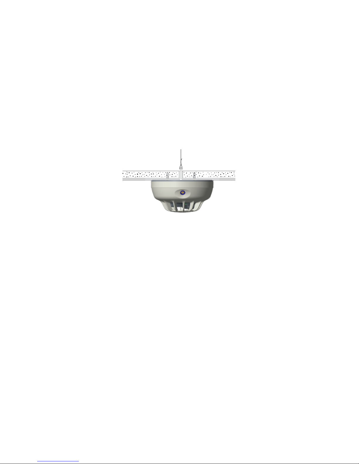
4. If the detector is mounted to a removable ceiling t ile, the tile must be secured
with the appropriate fasteners to prevent tile removal or mount the detector
across a ceiling panel support as shown in Figure 2.
IMPORTANT:
1. Both batteries MUST be installed for the detector to operate properly.
2. The detector will initiate a low battery trouble if both batteries are not
installed within 90 seconds of each other. The detector must be power cycled
to clear this fault.
Figure 2 Proper Mounting to Ceiling Tile
Cautions:
1. Make sure the batteries are firmly installed in the smoke detector battery
compartment.
2. The unit must be secured tightly to the wall, so as to not be dislodged.
3. Test the unit after any service, battery change or as often as local or national codes
dictate.
DO NOT Install Detectors in the Following Areas:
• In or near areas where particles of combustion are normally present such as
kitchens; in garages; near furnaces, hot water heaters, or gas space heaters.
• In an area where cross-interference gasses are present. Cross interference
gasses include but are not limited to: Methane, Butane, Heptane, Ethyl Acetate,
Isopropyl Alcohol, Carbon Dioxide, Ammonia, Ethanol, Toluene, Trichloroethane
and Acetone.
• Within 10 feet of a flame fueled appliance.
• In any area that is out of the detectors environmental specification range.
• In wet or excessively humid areas, or next to bathrooms with showers.
• In dusty, dirty, or insect-infested areas.
• Near fresh air inlets or returns or excessively drafty areas.
NOTE: Consult NFPA 72, NFPA 720, the local Authority Having Jurisdiction (AHJ),
and/or applicable codes for specific information regarding the spacing and placement
of smoke and/or CO detectors. Refer to techn ical bulletins part numbers IM-300-TBRevB and IM-350-TB-Rev A for more information.
Page 5
P/N IM-360 Rev. A
2018 Tyco Fire & Security GmbH
5
Tamper-Resistant Feature
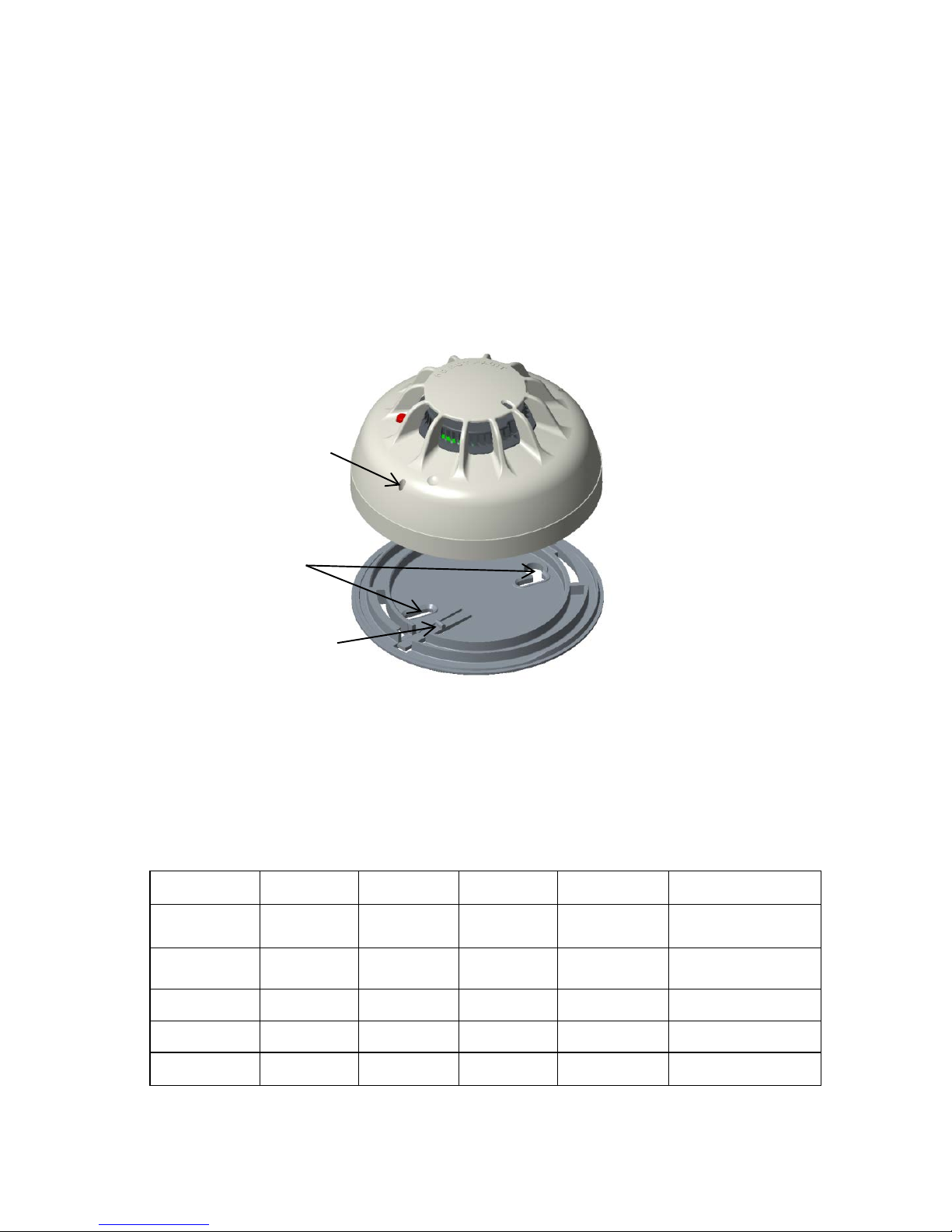
The Model 360/370 includes a tamper-resistant feature that prevents removal of the
detector from the mounting base without the use of a tool. To engage the tamper-resistant
feature, cut the small plastic tab located on the mounting base (Figure 3), and then install
the detector. To remove the detector from the base once it has been made tamper
resistant, insert a small screwdriver or similar tool (2mm max diameter) into the detector
cover hole. Push the tool far enough into the hole shown in Figure 3 to depress the tamper
release tab located on the skirt of the mounting base and turn the detector
counterclockwise.
Figure 3 Tamper Resistant Feature
LED and Sounder Operation:
The 360/370 detectors are equipped with a tricolor LED status indicator and a sounder* to
provide local visual and audible indication of the detector’s status. The table below explains
the LED and sounder functions.
LED Status and Sounder Operation
Condition Green LED Red LED Yellow LED Sounder
Transmitted Signal
to FACP
Power up
Blink 5
times***
Off
Blink 7
times***
Off Power up reset
Standby Off Off Off Off
Test (check in)
every 90s
Smoke Alarm Off On Steady Off Temporal 3* Smoke Alarm
Heat Alarm Off On Steady Off Off Heat Alarm
CO Alarm Off
Blink every
1s
Off Temporal 4* CO Alarm
Cut this small tab
to activate tamper
resistant feature.
Detector
mounting
holes
Tamper resistan t
feature release hole
Page 6

P/N IM-360 Rev. A
2018 Tyco Fire & Security GmbH
6
Test Switch
Pressed and
released
within 3s
(normal
standby)
Off On Steady Off
2 cycles of
Temporal 3
None
Test Switch
Pressed
more than 3s
(Fast Test)
Off
On Steady
then every
1s upon
detecting
CO gas
Off Temporal 4*
CO Alarm
Upon detecting CO
gas
Test Switch
pressed (in
low batt)
Off Off
Blink
every 45s
Silenced for
12 hours
Low Battery every
90s
Test Switch
pressed (in
alarm)
Off On Steady Off
Silenced for 5
minutes
Alarm every 60
seconds
Maintenance
or Fault
Off Off
Blink every
5s
Off
Maintenance
Required Trouble
Every 90s
Hardware
Fault
Off Off
Blink every
5s
Off Hardware Flt
CO-Cell
Trouble
Off Off
Blink every
5s
Chirp every
45s
CO-Cell Trouble
Every 90s
CO-Cell End
of Life
Off Off
Blink every
10s
Chirp every
45s
CO-Life Trouble
Every 90s
Freeze Off Off Off Off
Freeze Trouble
Every 90s
Tamper Off Off Off Off
Tamper Trouble
Every 90s
Low Battery Off Off
Blink every
45s
Chirp every
45s
7 days af ter
low battery
detection
Low Battery
Trouble Every 90s
Dip switch
config error
Off Off
Blink every
2s
Off None
Table 1
*Sounder will activate if the detector is configured for sounder on. Temporal 4 will
sound continuous for 4 minutes then change to once every 60 seconds.
** A signal test will be transmitted.
*** When the unit powers up, you will see a sequence of 7 yellow LED flashes followed
b y 5 green LED flashes. The 5 green flashes will not occur if the detector has a fault.
Smoke Alarm Operation:
Page 7

P/N IM-360 Rev. A
2018 Tyco Fire & Security GmbH
7
When the detector s enses smoke the Red LED turns on steady, the internal s ounder* turns
on in the temporal 3 pattern and the following occurs:
1. An initial alarm signal is transmitted.
2. A 60 second delay occurs. If smoke clears the detector during this delay the alarm
condition is reset and a restore signal is sent ending the alarm cycle.
3. The continued alarm condition causes a repeat alarm transmission.
4. Another 60 second delay as in step 2 occurs.
5. Step 4 repeats at 60 second intervals until the detectors alarm condition is cleared.
*If the detector is configured as sounder on.
CO Alarm Operation:
When the detector senses CO toxic gas which exceeds minimum alarm levels, the Red LED
blinks, the internal sounder* turns on in the temporal 4 pattern and the following occurs:
1. An initial alarm signal is transmitted.
2. A 60 second delay occurs. If CO gas clears the detector during this delay the alarm
condition is reset and a restore signal is sent ending the alarm cycle.
3. The continued alarm condition causes a repeat alarm transmission.
4. Another 60 second delay as in step 2 occurs.
5. Step 4 repeats at 60 second intervals until the detectors alarm condition is cleared.
*If the detector is configured as sounder on. Temporal 4 will sound continuous for 4 minutes
then change to once every 60 seconds.
Heat Alarm Operation:
When the heat thermistor senses temperature in ex cess of 135 F, the internal sounder* turns
on in the temporal 3 pattern and the following occurs:
1. An initial alarm signal is transmitted.
2. A 60 second delay occurs. If the temperature at the heat sensing thermistor falls under
135 F during this delay, the alarm condition is reset and a restore signal is sent ending the
alarm cycle.
3. The continued alarm condition causes a repeat alarm transmission.
4. Another 60 second delay as in step 2 occurs.
5. Step 4 repeats at 60 second intervals until the detectors alarm condition is cleared.
*If the detector is configured as sounder on.
Tandem Sounder Feature
The detector can be installed in both living and common areas. When it is in stalled in common
areas do not program the tandem feature. The model 360/370 allows the detectors piezo
sounder to be turned on or off in tandem with an RF command signal from the FACP. This
enables an installation to be programmed so that when an alarm is received from any
detector in alarm the FACP can activate the sounder in one or more detectors that are not in
alarm. When activated, the sounder will turn on in either temporal 3 or temporal 4 patterns
depending on what detector type generated the alarm . Note: Only the detector in alarm
will transmit an alarm signal. This detector must be configured for tandem on and the
feature must be programmed into the FACP to function. Refer to the FACP manual for
additional information and programming instruction. If the detector i s in alarm due to local
detection the tandem silence signal or reset from the control panel will not silence the
sounder. If the detector is in alarm due to local detection and it receives the tandem on signal
the sounder will remain active even if the detector clears locally. A tandem silence s i gnal or
FACP reset will be required to turn off the sounder.
Detector Testing
Detectors must be tested after installation and following maintenance or battery replacement.
NOTE: Before testing, notify the proper authorities that maintenance is being
performed and the system will be temporarily out of service. Place the FACP in test to
prevent any unwanted alarms. Perform all of the applicable tests below based on the
Page 8

P/N IM-360 Rev. A
2018 Tyco Fire & Security GmbH
8
configuration of active sensors to properly test the 360/370 detector. If a detector fails any of
the tests below, it should be cleaned as outlined in the Maintenance section and retested. If
the detector still fails, it should be replaced.
Smoke Alarm Testing
Perform both tests A and B below. This test will only function if the detector has been
configured with an active smoke sensor.
A. Test Switch
Note: This test will onl y function if the detector is operating within its proper sensitivity limits
and is not in a trouble condition.
The purpose of this test is to check the functionality of the circuitry. It will not cause an alarm
signal to be transmitted.
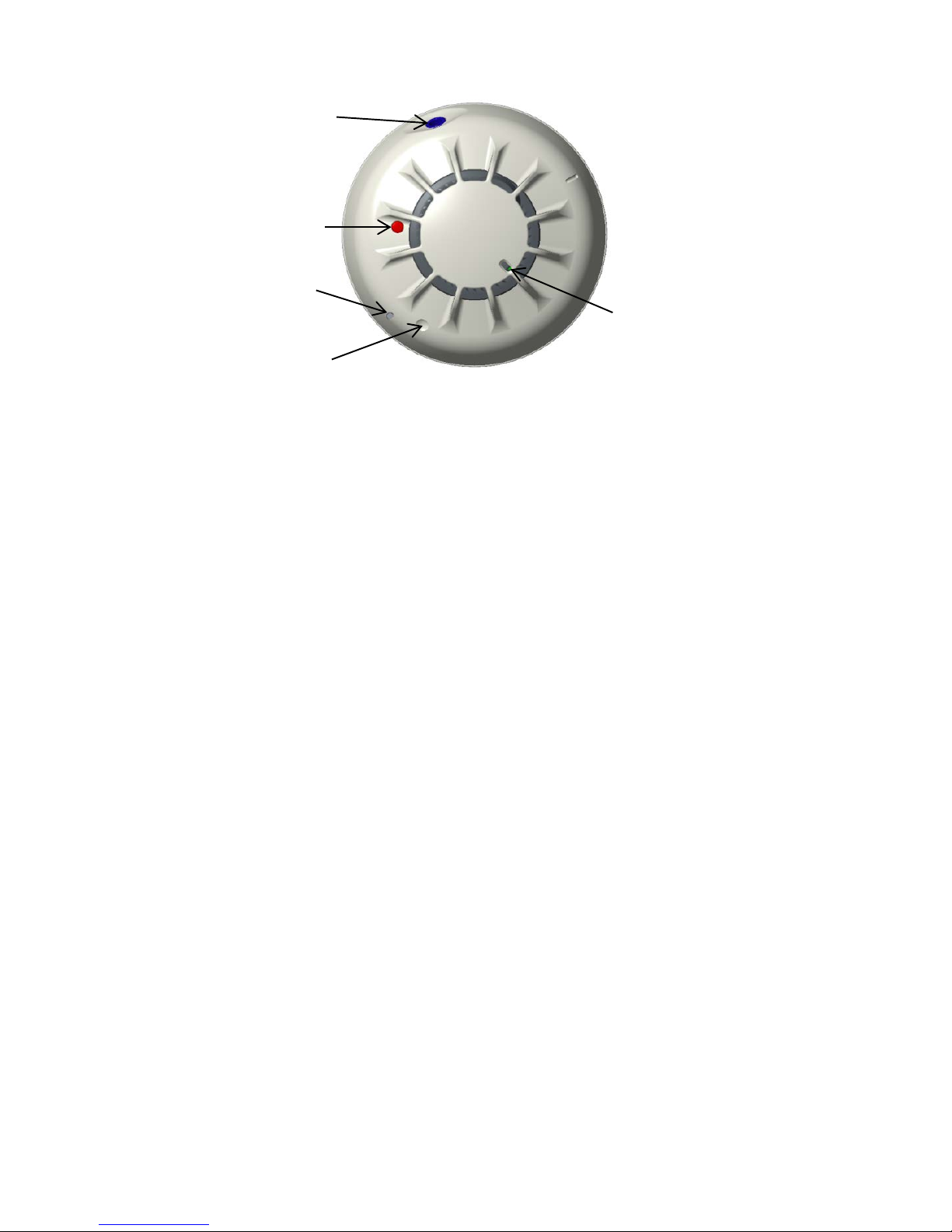
1. Locate the test swi tch opening on the detector housing. (Figure 4)
2. Insert a small screwdriver or s imilar tool ( 2mm max.) into the test switch opening; push
and hold for 2-3 seconds then release. If the button is held more than 3 seconds the detector
will enter the CO fast test. If this occurs, wait 20 seconds and the detector will go back to
normal then repeat step 2.
3. If the detector is within the listed sensiti vity limi ts, the f ollowing will occur:
a. The red LED turns on steady.
b. The sounder activates with the temporal 3 pattern. Note: The sounder for this
test will activate even if the detector is configured for sounder off.
4. Perform step B below.
B. Smoke Entry Test
Warning: This test will cause an alarm signal to be transmitted. Wait at least two minutes
after power up before performing this test.
1. Hold a smoldering punk stick or cotton wick at the side of the detector and gently blow
smoke through the detector until the unit alarms. Canned aerosol smoke is also an
acceptable method
2. Verify the alarm signal was received at the control panel.
3. Verify the red LED turns on steady and the sounder turns on in the temporal 3 pattern.
(only if the detector is configured for sounder on).
4. If both t est A+B pass, remove the panel from test mode and not ify the proper authorities
when the system is back in service.
5. If the detector failed either of the tests, it should be cleaned as outlined in the
Maintenance section. Rerun the test. If the detector still fails, it should be replaced.
CO Alarm Testing
Warning: This test will cause an alarm signal to be transmitted. This test will only
function if the detector is operating within its proper sensitivity limits and is not in a trouble
condition. The purpose of this test is to check the functionality of the CO sensor and
circuitry. This test will only function if the sensor has been configured with an active CO
sensor. The model 370 has a functional gas test mode which can be used to verify the
detector’s ability to sense carbon monoxide gas.
Page 9

P/N IM-360 Rev. A
2018 Tyco Fire & Security GmbH
9
To perform the alarm/functional gas test, follow the steps below:
1. Locate the detector test switch opening located on the detector cover (Figure 4).
2. Insert a small screwdriver or similar tool ( 2mm max.) into the test switch opening; push
and hold for 2-3 seconds then release.
3. The red LED will begin to blink as an indication of fast test mode.
4. While the LED is blinking spray a very small amount of canned CO gas tester such as
Solo brand C6 canned CO into the detector chamber area located on the top center area
of the detector (figure 4).
5. Upon successful gas entry and if functioning properly, the detector will alarm by blinking
the red LED once a second and the sounder turns on in a Temporal 4 pattern. (only if the
detector is configured for sounder on).
6. The alarm condition at the detector will time out in 20 to 60 seconds or when the CO gas
has cleared.
7. If gas entry is unsuccessful, the test will time out after 20 seconds.
8. When testing of the CO detector(s) is completed, remove the panel from test mode and
notify the proper authorities when the system is back in service.
9.
If the detector failed the tests, it should be cleaned as outlined in the Maintenance
section. Rerun the test. If the detector still fails, it should be replaced.
Heat Alarm Testing
Warning: This test will cause an alarm signal to be transmitted. This test will only
function if the detector is operating within its proper sensitivity limits and is not in a trouble
condition. The purpose of this test is to check the functionality of the heat sensor and
circuitry. This test will only function if the sensor has been configured with an active heat
sensor.
To perform the heat alarm test, follow the steps below:
1. Using a hair dryer or heat gun, direct the heat toward the thermistor in the center face of
the detector, holding the heat source 12 inches away to avoid damage to the plastic
housing.
2. The LED on the detector will turn on continuously and an alarm signal will be sent to the
panel when temperature reaches the 135° F alarm set point. Remove the heat source.
3. Wait for the detector to cool and return to normal standby.
4. If the test passes, remove the control panel from test mode and notify the proper
authorities when the system is back in service.
5. If the detector failed the test, it should be cleaned as outlined in the Maintenance
section. Rerun the test. If the detector still fails, it should be replaced.
Page 10
P/N IM-360 Rev. A
2018 Tyco Fire & Security GmbH
10
Figure 4 LEDS, Sounder, Test Switch and Signal Test Locations
Signal Test
The test must be performed while the smoke detector is held in its intended mounting
location. Install batteries into the smoke detector. Initiate the test by placing a strong magnet
on the smoke detector housing at the location shown in figure 3 for 2 s econds. The model
360/370 piezo sounder will beep once. A delay of up to 15 seconds will occur followed by
either one or two beeps. One beep indicates an unacceptable location and two beeps
indicate an acceptable location. If only one beep is heard t hen relocate the model 360/370
mounting position closer to the nearest repeater or control panel and perform the test again.
Continue this procedure until 2 beeps are achieved. Do not mount the smoke detector unless
2 beeps are heard when performing 5 consecutive signal tests. This test must be performed
before and after detector installation. Note: A CWSI repeater or F ACP m ust be powered up,
installed and enrolled before running this test.
Base Code Clearing
When a detector is enrolled to a control panel a base code is programmed into the detector.
Once the base code is programmed the detector will only communicate with a control panel
with that specific base code. It may be desirable to clear this base code if the detector is
commissioned at a different site and it is nec essary to communicate with a different control
panel.
To clear the base code:
1. Remove the batteries from the detector and wait 20 seconds before step 2.
2. Reinstall one battery while holding the test switch.
3. Continue to hol d the test switch until a sequence of two long and two short beeps are
heard from the detector sounder then release.
4. The base code is now cleared.
5. Refer to the control panel manual for more information on base codes.
Test Switch Functions
Sounder
Test Switch
Tamper
Release
Magnet Signal
Test
LED Indicator
Page 11

P/N IM-360 Rev. A
2018 Tyco Fire & Security GmbH
11
This switch has multiple functions and is located in an opening on the detector housing as
shown in figure 4. To activate the switch insert a small screwdriver or similar tool (2mm max.)
into the test switch opening; push and hold for the time associated with the desired test.
Pressing this switch will not cause an alarm at the control panel. The funct ionality of the
button will be dependent upon the detector configurati on. For example the button will not
perform the CO fast test if the detector is configured as a smoke alarm.
The functions of the Test Switch are:
1. Performs a signal test when not in alarm.
2. Test the functionality of the detectors circuitry when pressed for 2 seconds while the
detector is in standby.
3. Activate CO fast test mode for 20 seconds when pressed and held for more than 3
seconds.
4. Silence the low battery chirp for 12 hours if pressed during low battery.
5. Silence the detector sounder for 5 minutes if pressed anytime while the sounder is turned
on in the temporal pattern.
Low battery
The model 360/370 detector periodically tests each battery for a low battery condition. The
voltage on either battery has to be at or below 2.7V nominally for two consecutive batt ery
tests before a low battery trouble condition is transmitted. When a low battery is detected the
yellow LED will blink every 45 seconds and a low battery trouble signal will be transmitted
and repeated every 90 seconds. Onc e the low battery condition is present for 7 days, t he
piezo sounder will begin to chirp once every 45 seconds. This gives the service technician
time to replace the battery prior to audible not ification. The low battery trouble signal will be
transmitted and the piezo sounder will chirp for an additional 7 days. Pressing the smoke
detector test button will silence the sounder chirp for 12 hours however the low battery trouble
signal will continue to be transmitted every 90 seconds. Where more than one type of trouble
exists, all will be repeated in increments of 90 seconds. Note: When the detector is in low
battery trouble the test button will not perform signal survey or detector testing
functions in order to conserve power. When changing the batteries always replace both
batteries with new ones. Refer to the Battery Installation and Replacement section for
instructions on battery replacement.
Battery Installation and Replacement
Warning:
1. Always install new batteries of one of the approved types as listed in the
specifications section of this manual and the product label.
2. Always replace both b atteries with new ones when a low battery trouble is
indicated.
3. The detector will initiate a low battery trouble if both batteries are not
installed within 90 seconds of each other. The detector must be power cy cled
to clear this fault.
4. When a battery is first inserted, a low battery test is performed. If the battery
passes the test, the LED’s should indicate normal standby. If the battery
does not pass this test, the detector will not power up. Fresh batt eries should
be installed. If the detector still doesn’t power up with k nown g o od batte ries,
replace the detectror.
To replace the batteries:
Page 12

P/N IM-360 Rev. A
2018 Tyco Fire & Security GmbH
12
1. Place the FACP in Test mode to prevent any unwanted alarms.
2. Remove the detector from its mounting base by twisting the detector counterclockwise.
Open the batteries cover and remove and dispose of both batteries properly. If the T amper
Resistant feature was implemented during installation then follow the instructions under that
section for removing the detector.
3. To insure proper power down sequence, wait a minimum of 20 seconds before instal ling
new batteries.
4. Install 2 new approved 3 volt lithium batteries in the battery compartment following the
polarity markings. The LED’s will indicate power up and a power up reset trouble signal
should be indicated on the FACP within 60 seconds after installati on of the new batteries. A
tamper trouble will also be indicated on the FACP if the smoke alarm is not att ached to the
base.
5. Reinstall the smoke detector onto the mounting base by turning the detector clockwise.
6. The LED’s should indicate Normal Standby conditions as shown in the LED status and
sounder table. Note: The detector will initiate a l ow battery trouble if both batteries are
not installed within 90 seconds of each other.
7. Test the detector for alarm operations described in the Detector Testing section of this
manual.
8. If the detector does not function as described after battery replac ement then start over at
step 2. If it still doesn’t operate correctly then replace the detector.
9. Remove the panel from test mode.
Tamper
The Models 360/370 contain a built in switch that will cause a tamper signal to be transmitted
if the detector is removed from its mounting position. Upon detector removal, a tamper signal
is transmitted and repeated every 90 seconds until the detector is mounted on its base. Note:
This trouble is self-restoring on some CWSI control panels. Refer to the control panel manual.
Note: This trouble can displayed as a Tamper or Tamper/Maint dependent on FACP
compatibility. Refer to the FACP manual for more information.
Freeze
The Models 360/370 will report a freeze trouble condition when the detectors installed
ambient temperature falls bel ow 32°F. This signal is a warning that the detectors operating
environment is approaching its lower temperature operating limit. T he trouble will selfrestore when the temperature rises to 36°F or above. Note: Indication of this trouble is
dependent on FACP compatibility. Refer to the FACP manual for more information.
Power Up Reset
The Models 360/370 will report this trouble when first powered up. This is normal. If a power
up reset reoccurs any time after the initial indication then the detector is malfunctioning.
Replace the detector.
Test Failure
The Models 360/370 transmit a periodic test signal. This trouble condition will be displayed
within 200 seconds on the FACP if the tes t signal is not received. The detector may be out
of reception range of a repeater or FACP or the detector may have an internal problem.
Perform the signal test described in this manual to determine if there is a reception problem.
Page 13

P/N IM-360 Rev. A
2018 Tyco Fire & Security GmbH
13
Note: This trouble is self-restoring on some CWS I control panels. Refer to the control panel
manual.
Hardware Fault
The Models 360/370 monitors the integrity of the hardware and communications between the
smoke detector board and the RF transmitter board internal to the smoke detector. A
Hardware Flt trouble will be displayed on the FACP if there is a hardware failure or
communications failure between the two boards. If this occurs replace the smoke detector.
CO Cell Trouble
The Model 370 monitors the CO cell for CO/toxic gas detection integrity. If the detector reads
a fault with the CO cell’s ability to detect CO/toxic gas a CO-Cell or Tamper/Maint trouble will
be sent and displayed on the FACP. The detectors yellow LED will blink every 5 seconds
and the sounder will chirp every 45 seconds. Replace the detector. Note: Indicat i on of t his
trouble is dependent on FACP compatibility. Refer to the FACP manual for more
information.
CO End of Life Trouble
The detectors CO cell has a 10 year life limitation before the detector needs to be replaced.
The Model 370 monitors the CO cell for end of life timeout and will send a CO-Life or
Tamper/Maint trouble to the FACP when end of life is reached. The detectors yellow LED will
blink every 10 seconds and the sounder will chirp every 45 seconds. Replace the detector.
Note: Indication of th is trouble is dependent on FA C P compatibility . Refer to the FACP
manual for more infor mat ion .
Maintenance Req:
The Models 360/370 contain circuitry that allows the detector to automatically adjust its
sensitivity within factory limits when it bec omes more sensit ive due to cont aminants settl ing
in its chamber. If the s ensiti vity has shift ed outside t he list ed limits t he yellow LED will flash
every 5 seconds and a maintenance required signal will be sent to the FACP and repeated
every 90 seconds until the condition is corrected. Perform maintenance on the detector as
described in this manual. If the problem persists, replace the detector.
Maintenance
Perform maintenance yearly or whenever a Maintenance Req. Trouble s ignal is indicated.
Warning: Never disassemble the detector cover to the chassis containing the circuit
boards.
NOTE: Before performing maintenance on the detector, notify the proper authorities that
maintenance is being performed and the system will be temporarily out of service. Place the
control panel in test mode to prevent any unwanted alarms.
The batteries must be removed from the detector before performing maintenance of any kind.
1. Place the FACP in Test mode to prevent any unwanted alarms.
2. Remove the detector by turning counterclockwise, open the battery cover and remove the
batteries. If the Tamper Resistant feature was implemented during installation then follow the
instructions under that section for removing the detector.
3. Vacuum the chamber area or use canned air to remove any dust or debris.
4 Reinstall the batteries and reattach the smoke detector ont o the mounting base by turning
the detector clockwise.
5. Test the detector as described in the Detector Testing section of this manual.
Page 14

P/N IM-360 Rev. A
2018 Tyco Fire & Security GmbH
14
6. If the detector does not function properly during testing then start over at step 2. If it still
doesn’t operate correctly then replace the entire unit.
7. Remove the panel from test mode.
Specifications:
• Battery Type: Qty. 2 Type - 3 Volt Lithium; Duracell DL123 / Ultra123
• Battery Life: 12 Months Minimum
• Battery Replacement: Upon Low battery report and/or during annual maintenance.
• Average Standby Current: Model 360/370 32.8ua Tandem mode 71.5ua
• Average Alarm Current: Model 360/370 36ma
• Tamper Switch: On base
• Sounder: 85db at 10’ temporal 3 and 4 pattern.
• Reset: Automatic
• Sensitivity: 2.0% nominal
• Low battery threshold: 2.7V
• Operating Temperature Range: 32°F to +100°F.
• Operating Humidity Range 0 to 95% RH.
• Testing: Follow this manual and NFPA 72, NFPA 720 or local requirements.
• Transmission: In compliance with FCC part 15
• Test Transmission: Every 90 seconds.
• Mounting base diameter 117.6mm/4.63in.
• Weight 6.4 oz.
FCC Statement
Important: Any changes or modifications not expressly approved by the party responsible for
compliance could void the user’s authority to operate the equipment
Page 15

P/N IM-360 Rev. A
2018 Tyco Fire & Security GmbH
15
This device complies with part 15 of the FCC Rules. Operation is subject to the following two
conditions: (1) This device may not cause harmful interference, and (2) this device must
accept any interference received, including interference tha t may cause undesired operation.
Disclaimer
The information contained in this document is believed to be accurate and reliable
at the time of printing. Known corrections or omissions may be found on errata sheets
included in the various product manuals. However, CWSI a Tyco Fire & Security GmbH
Company (CWSI), may not be held accountable for errors or omissions in this or other CWSI
publications. No license is granted by im plication or otherwise under any patent ri ghts of
CWSI. Applicable terms and conditions can be found at
http://tycofsbp.com/TFPPTerms_of_Sale/TFPPTerms_of_Sale.pdf
 Loading...