

Page 1
DSPA-1612
(16) 2x1 Screen Splitters
Instruction Manual
Thank you for purchasing one of our products. Please read this manual before using this
product. When using this product, always follow the instructions contained in this manual,
and pay attention to the safety information.
Page 2

Do not expose this product to water, rain or moisture.
Doing this can result in electric shock or re.
Never take this product apart or try to modify it.
Doing so is very dangerous and could result in electric shock.
Do not store this product near open ame.
Do not use this product near open ame or place lit or ammable items, such as
candles, incense, ect., on it.
Do not place any containers lled with water or other liquids near this product.
Doing so could result in re or electric shock if the liquid spills and enters the product or
gets it wet. If a liquid spills near this product, unplug the product immediately.
Do not remove or insert the power supply with wet hands.
Doing so could result in electric shock.
Do not use the power supply in any of the following ways.
Doing so could result in re or electric shock.
Modifying or heating the power cable
Damaging the power cable
Bending or tugging on the power cable unnecessarily
Knotting or kinking the power cable
Setting heavy objects on the power cable
When moving this product , rst unplug the power supply from the outlet. Do not
tug the cable or move this product with the power supply plugged into the outlet.
Doing so could damage the cable, possibly resulting in re or electric shock.
To reduce the risk of electric shock, do not remove the cover.
No parts inside the product can be serviced by the user. If your product needs service
contact:
Compu-Video Systems Inc. at (845) 737-7009.
Usage Environment
Avoid using or storing this product in areas such as those listed below. Doing so could
damage the product or cause it to malfunction.
Areas exposed to heat or ames
Humid areas and areas where water is used
Handling this product
Do not drop or apply a strong force to this product or any included or connected parts.
Do not spill liquids around or inside this product or drop ammable objects around or
inside it.
Power Supply
Only use the supplied power supply which is designed specically for this product.
Do not allow the plug to come into contact with metal or water.
This Product is not designed for contact medical use
Do not use this product for medical applications that could result in patient contact.
The information in this manual is believed to be accurate. It is intended for professional
end users having the skills to evaluate and use the data properly. Compu-Video assumes
no liability in connection with damages incurred while using this product.
Tel: (845) 737-7009 • Fax: (845) 737-0426 • Web: www.compuvideosystems.com
Page 3
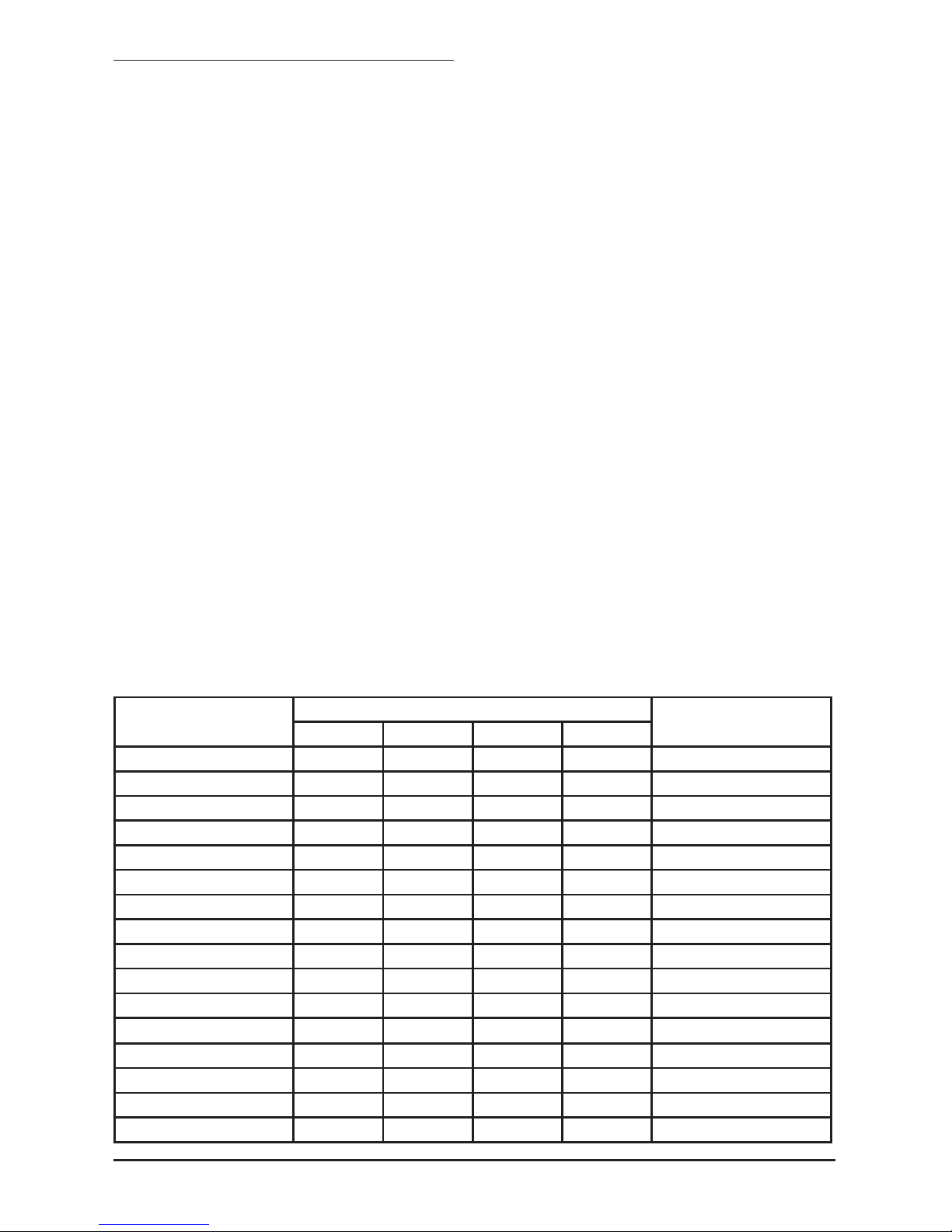
Model # Of Inputs # Of Outputs Controls Special Features
DSPA-1612 32 48
Gain & High
Frequency Adj.
& DSP Adj.
Ground Loop & Surge
Protection
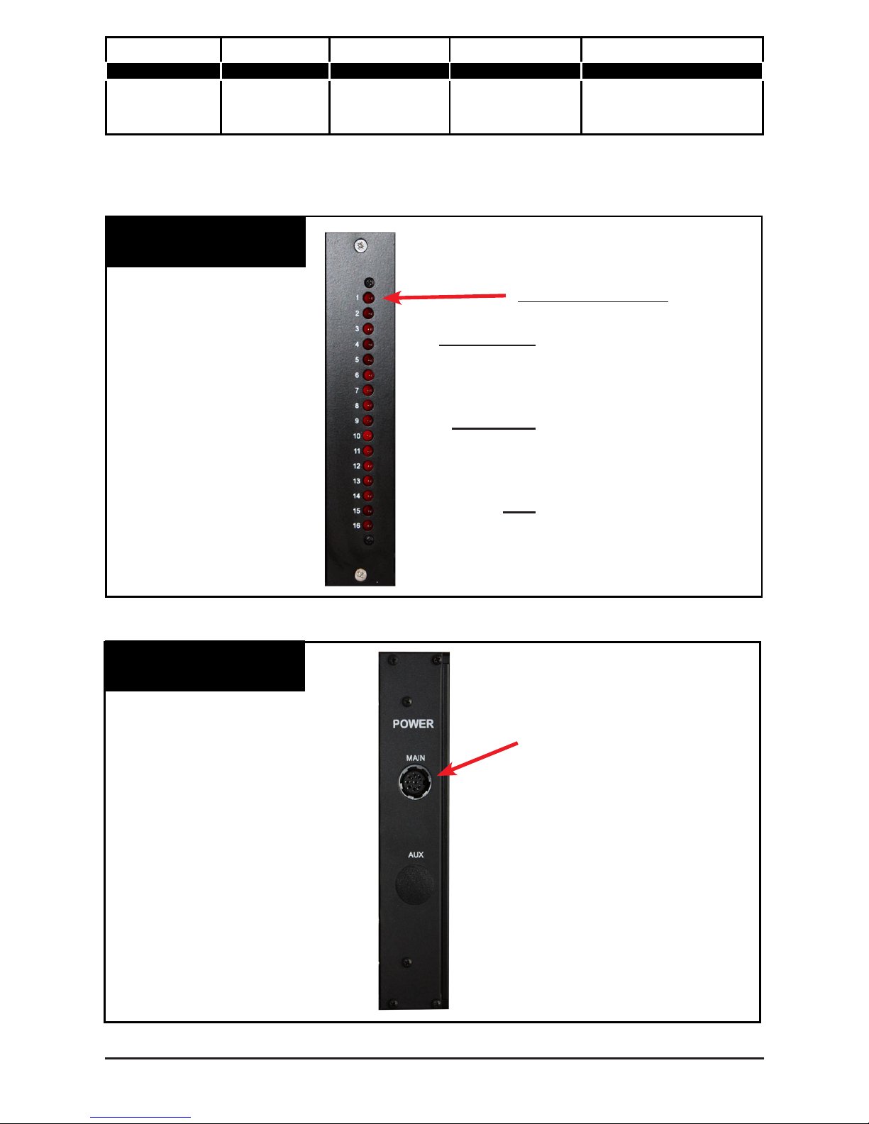
Fig. 1
Front View Of Power Card
Board Indicators
ON-STEADY Board has power and
both video sources are
good.
FLASHING One or both video
sources are missing or
the board has a problem.
OFF There is no board or the
power if off on the board.
Fig. 2
Rear View Of Power Card
Power In From CVP-0523
Tel: (845) 737-7009 • Fax: (845) 737-0426 • Web: www.compuvideosystems.com
The DSPA-1612 is a system that consists of a CH-34 with a power supply, a Power
Distribution / Indicator Card, a Dual 32 channel switcher card, and 16 DSPABS-12 cards.
Page 4
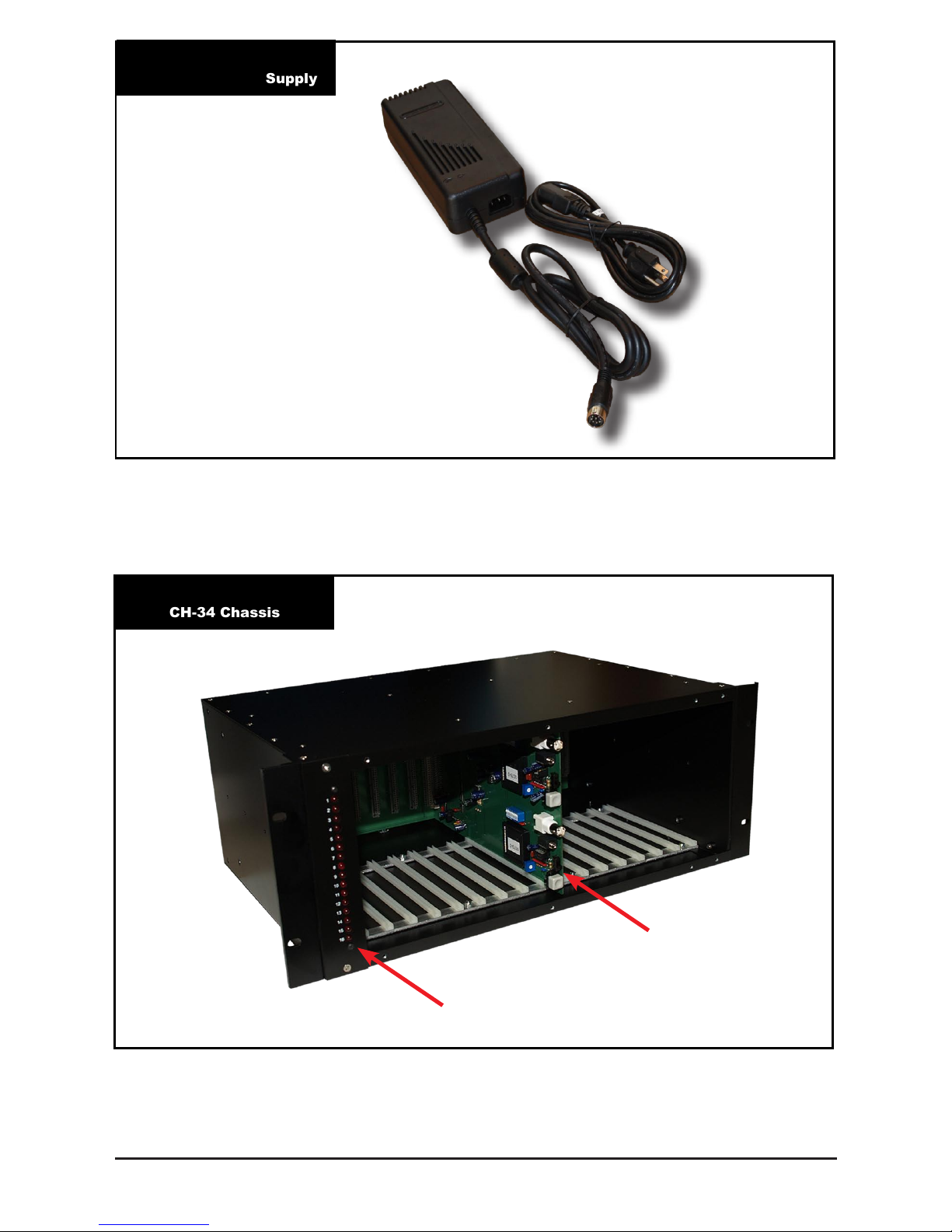
Fig. 3
CVP-0523 Power Supply
(Fig 3.) CVP-0523 is a 120VAC To 5 Volt DC @ 23 Amp Table Top Power Adaptor With
110 Power Cord.
Tel: (845) 737-7009 • Fax: (845) 737-0426 • Web: www.compuvideosystems.com
Fig. 4
CH-34 Chassis
Switcher Card
Power Distribution Card
Page 5
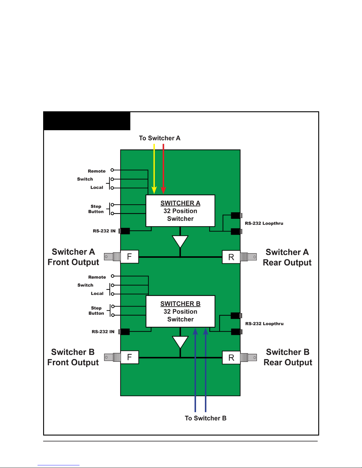
Fig. 5
Diagram Of Switcher Card
The dual 32-channel switcher card has the upper 32 channel switcher accessing the outputs of the Video DA side of the DSPABS-12 cards and the lower switcher accessing the
screen splitter output from the DSPABS-12 card.
The switchers have 2 types of controls.
1. Local “step” push button controls
2. Remote RS-232 Control
Each switcher is independently controllable
(Note) The lower switcher “looks” at each output 2x before going to the next card when
using the step button.
Tel: (845) 737-7009 • Fax: (845) 737-0426 • Web: www.compuvideosystems.com
Page 6
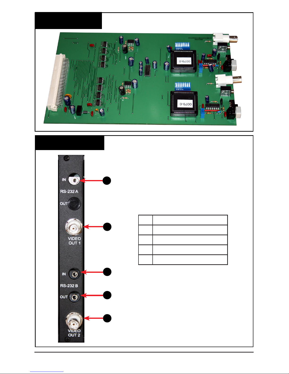
Fig. 6
Switcher Card
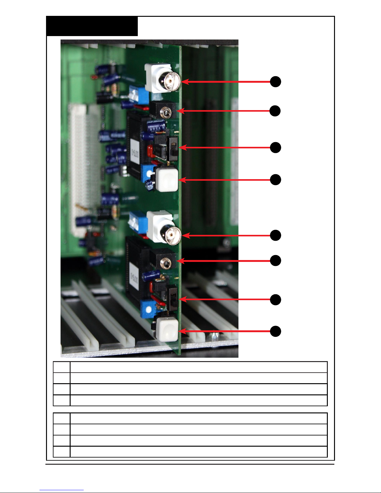
Fig. 7
Rear View Of Switcher Card
1
2
3
4
5
1
RS-232 In For Switcher 1
2
Video Out 2 For Switcher 1
3
RS-232 In For Switcher 2
4
RS-232 Loop For Switcher 2
5
Video Out 2 For Switcher 2
Tel: (845) 737-7009 • Fax: (845) 737-0426 • Web: www.compuvideosystems.com
Page 7
1
2
3
4
5
6
7
8
Fig. 8
Switcher Card Controls
1 Video Out 1 For Switcher 1, Outputs From DA 1 & DA 2
2 RS-232 Control For Switcher 1
3 UP - RS-232 Control For Switcher 1 DOWN- Local Control For Switcher 1
4 Step Button For Local Control Of Switcher 1
5 Video Out 1 For Switcher 2, Screen Splitter Output
6 RS-232 Control For Switcher 2
7 UP - RS-232 Control For Switcher 2 DOWN- Local Control For Switcher 2
8 Step Button For Local Control Of Switcher 2
Tel: (845) 737-7009 • Fax: (845) 737-0426 • Web: www.compuvideosystems.com
Page 8
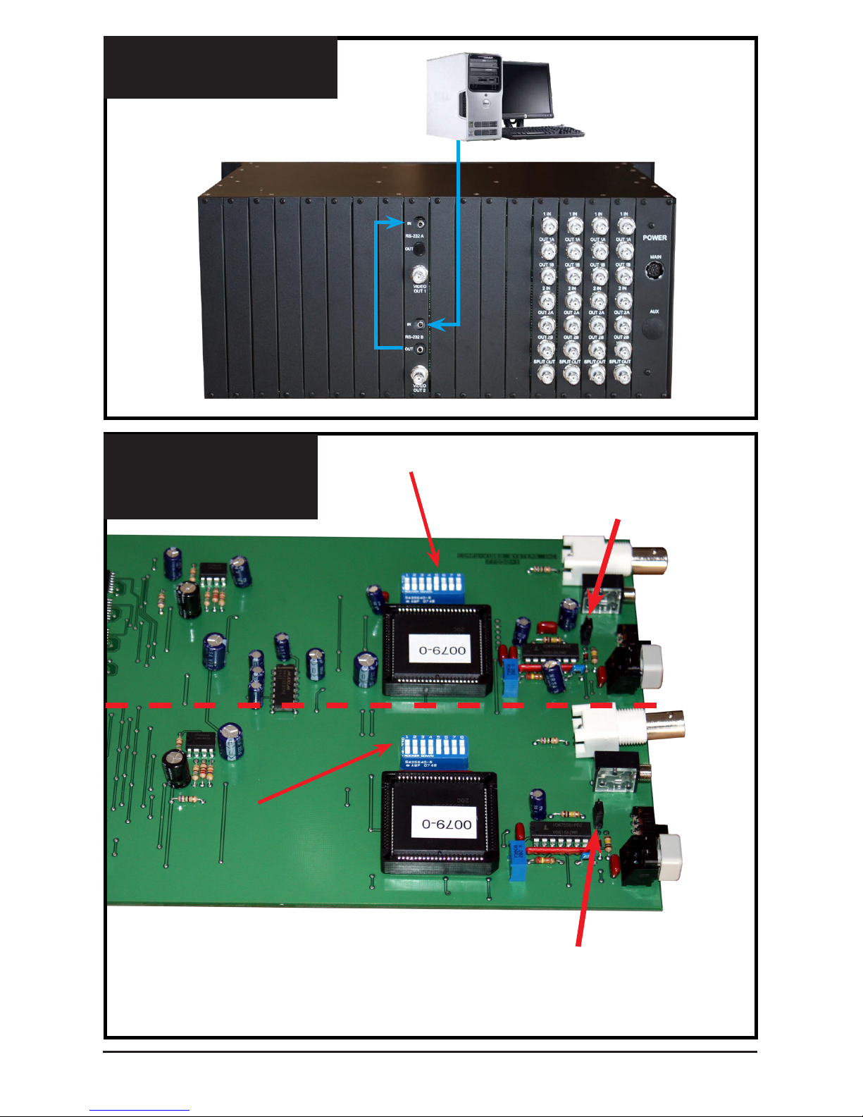
Fig. 10
Master Slave Diagram
For Both Switchers
8 pos Dip Switch
Master Slave Suitcase Jumper
Move jumper to the right
to place in slave position
8 pos Dip Switch
Master Slave Suitcase Jumper
Move jumper to the right
to place in slave position
Switcher 1
Switcher 2
Fig. 9
Master / Slave Unit Setup
Tel: (845) 737-7009 • Fax: (845) 737-0426 • Web: www.compuvideosystems.com
RS-232 Connection
Page 9
MULTI-SWITCHER SETUP:
A CS-1600 can be used as a master switcher to be fed by the DA-3212 slave switchers,
or a DA-3212 can be set up as a master if desired. To connect multiple units together to
enlarge the number of inputs you must set the slave units up for the proper addresses.
A) Determine which unit will be the master. All units are preset as masters from the
factory. Put it aside.
B) On each of the slave units:
Disconnect the power to the unit.
Remove the switcher card
Using the master slave diagram Fig. 13, locate:
The Master/slave suitcase jumper
The 8 pos Dip switch
C) Determine the ID number to be used for each slave unit,
(i.e. unit 16, or 15 or 14....). Mark the unit as to the ID number it is set for. Written in
pencil on the bottom will do the trick!
D) Set the suitcase jumper to the Slave position as shown in the master slave jumper
setup diagram.
E) Set dip switch #5 to the off position.
There is an eight position dip switch located on the control board. It is factory set for
machine #1 and the suitcase jumper is set for a master unit. To add addition units you will
start at the highest number and count down as shown in the system diagram. The master
will always be machine 1 unless there are 16 slave units. The slaves will start at 16 and go
down to 1 as they are added.
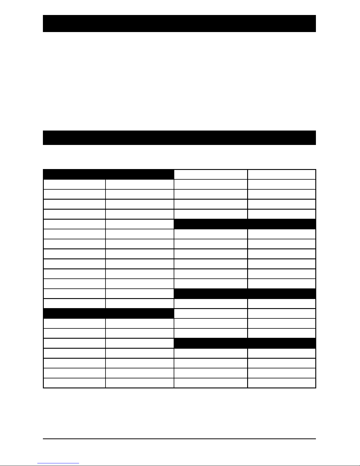
SWITCH CODE
SWITCH
MACHINE NUMBER
4 3 2 1
0000 ON ON ON ON 1
0001 ON ON ON OFF 2
0010 ON ON OFF ON 3
0011 ON ON OFF OFF 4
0100 ON OFF ON ON 5
0101 ON OFF ON OFF 6
0110 ON OFF OFF ON 7
0111 ON OFF OFF OFF 8
1000 OFF ON ON ON 9
1001 OFF ON ON OFF 10
1010 OFF ON OFF ON 11
1011 OFF ON OFF OFF 12
1100 OFF OFF ON ON 13
1101 OFF OFF ON OFF 14
1110 OFF OFF OFF ON 15
1111 OFF OFF OFF OFF 16
Tel: (845) 737-7009 • Fax: (845) 737-0426 • Web: www.compuvideosystems.com
Page 10

APPENDIX I
Command Protocol For RS-232 Port - IBM PC Type
10 CLS
15 LET E% = E%+1
30 PRINT”SELECT THE NUMBER OF THE SWITCHER TO BE CHANGED [1 TO 16]”;
40 INPUT A%
50 IF A% = 1 THEN LET A$ = ” ` ” (the key located to the left of the 1 key)
60 IF A% = 2 THEN LET A$ = ” a ”
70 IF A% = 3 THEN LET A$ = ” b ”
71 IF A% = 4 THEN LET A$ = ” c ”
72 IF A% = 5 THEN LET A$ = ” d ”
73 IF A% = 6 THEN LET A$ = ” e ”
74 IF A% = 7 THEN LET A$ = ” f ”
75 IF A% = 8 THEN LET A$ = ” g ”
76 IF A% = 9 THEN LET A$ = ” h ”
77 IF A% = 10 THEN LET A$ = ” i ”
78 IF A% = 11 THEN LET A$ = ” j ”
79 IF A% = 12 THEN LET A$ = ” k ”
80 IF A% = 13 THEN LET A$ = ” l ”
81 IF A% = 14 THEN LET A$ = ” m ”
82 IF A% = 15 THEN LET A$ = ” n ”
83 IF A% = 16 THEN LET A$ = ” o ”
100 PRINT ” SELECT INPUT TO BE CHANGED [1 - 32] ” ;
103 INPUT Y%
500 IF Y% = 1 THEN LET B$ = ” 0 ”
510 IF Y% = 2 THEN LET B$ = ” 1 ”
520 IF Y% = 3 THEN LET B$ = ” 2 ”
530 IF Y% = 4 THEN LET B$ = ” 3 ”
600 IF Y% = 5 THEN LET B$ = ” 4 ”
610 IF Y% = 6 THEN LET B$ = ” 5 ”
620 IF Y% = 7 THEN LET B$ = ” 6 ”
630 IF Y% = 8 THEN LET B$ = ” 7 ”
700 IF Y% = 9 THEN LET B$ = ” 8 ”
710 IF Y% = 10 THEN LET B$ = ” 9 ”
720 IF Y% = 11 THEN LET B$ = ” : ”
730 IF Y% = 12 THEN LET B$ = ” ; ”
800 IF Y% = 13 THEN LET B$ = ” < ”
810 IF Y% = 14 THEN LET B$ = ” = ”
820 IF Y% = 15 THEN LET B$ = ” > ”
830 IF Y% = 16 THEN LET B$ = ” ? ”
831 IF Y% = 17 THEN LET B$ = “ @ ”
The following is an example of a GW basic program used to control from 1 to 16 switchers.
The factory preset is machine #1, whose command is on line 910. The rst group of
characters are used to determine which machine number is being activated in a multi
switcher system. Normally machine #1 is used a default. The second group determines the
Input that will be switched to the output once the commands are sent. Line #905 represents
the settings for the RS-232 Com. port. If you have any questions please call Compu-Video
Systems at (845) 737-7009 between the hours of 9am and 5pm (EST).
Tel: (845) 737-7009 • Fax: (845) 737-0426 • Web: www.compuvideosystems.com
Page 11

832 IF Y% = 18 THEN LET B$ = “ A “
833 IF Y% = 19 THEN LET B$ = “ B “
834 IF Y% = 20 THEN LET B$ = “ C “
835 IF Y% = 21 THEN LET B$ = “ D “
836 IF Y% = 22 THEN LET B$ = “ E “
837 IF Y% = 23 THEN LET B$ = “ F “
838 IF Y% = 24 THEN LET B$ = “ G “
839 IF Y% = 25 THEN LET B$ = “ H “
840 IF Y% = 26 THEN LET B$ = “ I “
841 IF Y% = 27 THEN LET B$ = “ J “
842 IF Y% = 28 THEN LET B$ = “ K “
843 IF Y% = 29 THEN LET B$ = “ L “
844 IF Y% = 30 THEN LET B$ = “ M “
845 IF Y% = 31 THEN LET B$ = “ N “
846 IF Y% = 32 THEN LET B$ = “ O “
900 GOTO 905
905 OPEN “COM1:9600,N,8,1,RS,CS,DS,CD,BIN” AS #1
910 PRINT #1, A$ ; B$ ;
920 CLOSE #1
930 CLS
931 INPUT “DO YOU WISH TO EXIT THE DA-3212 PROGRAM [YES / NO]” ; A$
932 IF A$ = ”Y” THEN 960
933 IF A$ = ”y” THEN 960
934 IF A$ = ”N” THEN 10
935 IF A$ = ”n” THEN 10
960 CLS
962 END
A$ is the machine number on line 910
B$ is the input number on line 910
Tel: (845) 737-7009 • Fax: (845) 737-0426 • Web: www.compuvideosystems.com
Page 12

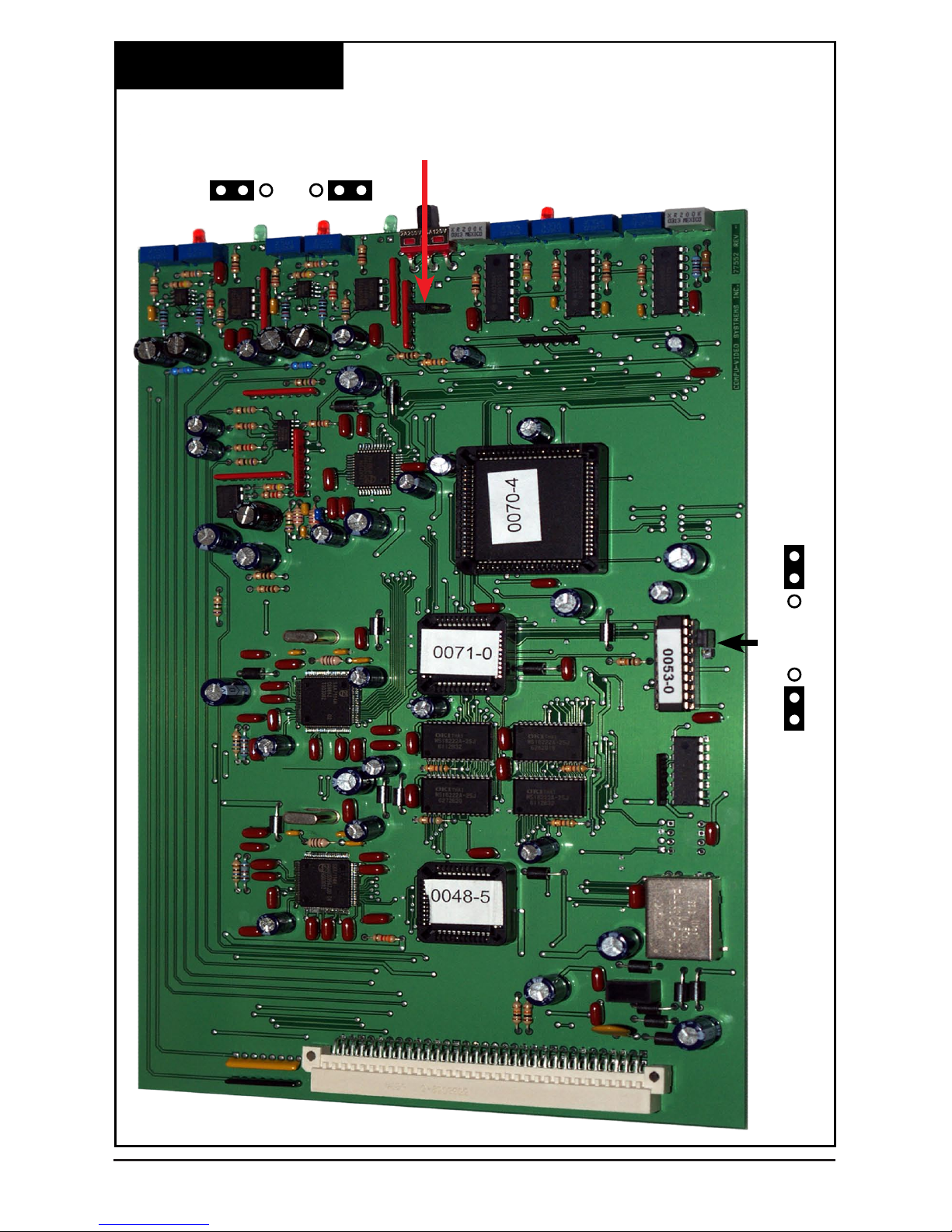
Fig. 11
DSPABS-12 Diagram
Tel: (845) 737-7009 • Fax: (845) 737-0426 • Web: www.compuvideosystems.com
The DSPABS-12 card has (2) 1x4 video compensating Distribution Ampliers with both
gain and high frequency adjustments. Two of the outputs go to the rear panel for outside
uses, one goes to the top video switcher, and the other one goes to the screen splitter
input.
Page 13

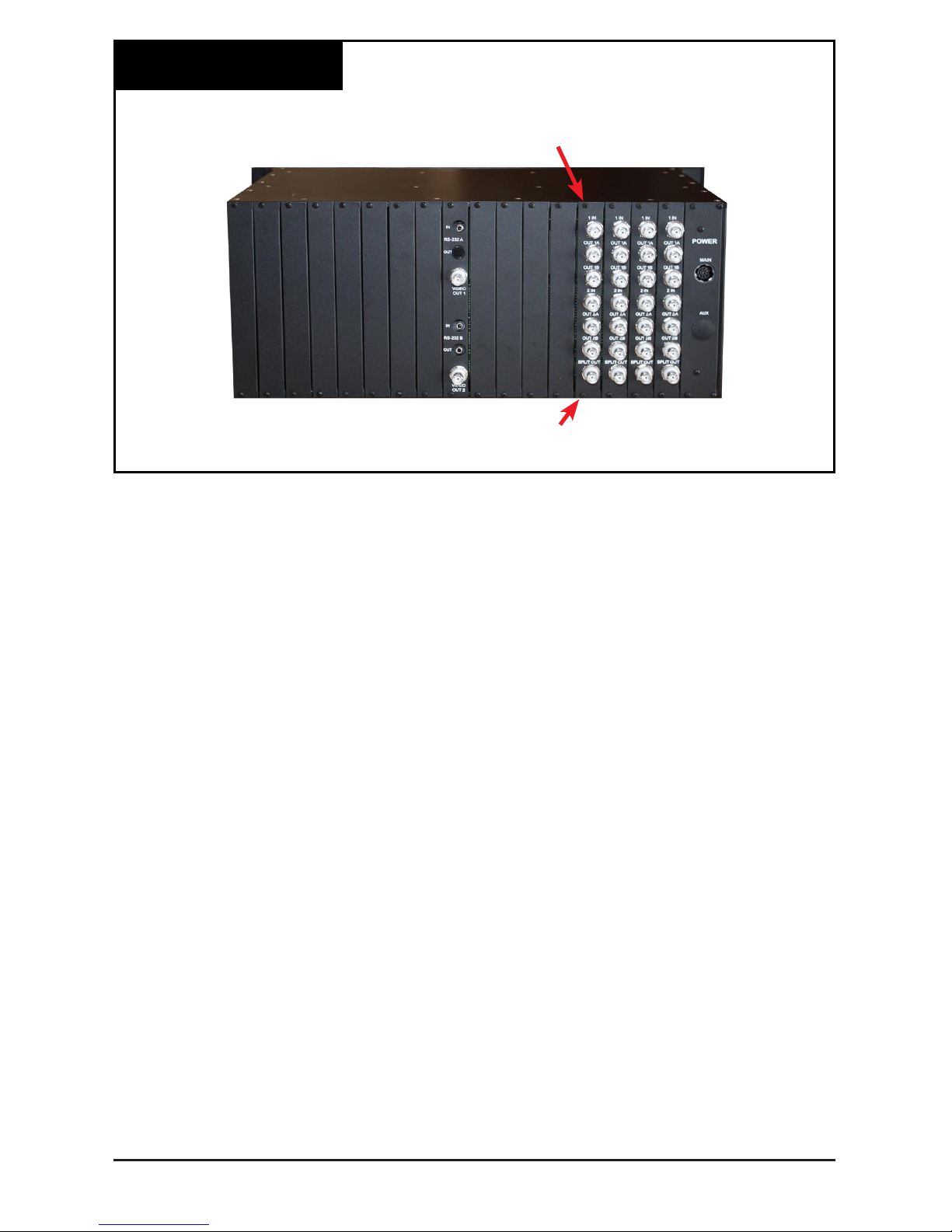
Fig. 12
DSPABS-12 Card
Fig. 13
Rear View Of DSPABS-12
1
3
5
6
7
1
Video 1 In
2
Video 1 Output 1
3
Video 1 Output 2
4
Video 2 In
5
Video 2 Output 1
6
Video 2 Output 2
7
Split Out (Video 1 & Video 2)
2
4
Tel: (845) 737-7009 • Fax: (845) 737-0426 • Web: www.compuvideosystems.com
Page 14

1
2
3
4
5
6
7
8
9
10
11
12
13
14
15
16
Channel A Switch Position Channel A Window
1
High Freq. Adj.
9
Up = A Only
10
Vertical End
2
Top Switcher Indicator Middle = Split
11
Vertical Start
3
Gain Adj. Down = B Only
12
Bottom Switcher Indicator
4
Video Presents Indicator
13
Horizontal End
Jumper Position
14
Horizontal Start
Channel B
17
Top 2 Pins = NYCT Split
5
High Freq. Adj. Bottom 2 = Variable Split
Channel B Window
6
Top Switcher Indicator
15
Horizontal Adj.
7
Gain Adj.
16
Vertical Adj.
8
Video Presents Indicator
Fig. 14
DSPABS-12 Controls
Tel: (845) 737-7009 • Fax: (845) 737-0426 • Web: www.compuvideosystems.com
17
Page 15

Tel: (845) 737-7009 • Fax: (845) 737-0426 • Web: www.compuvideosystems.com
The DSPABS-12 is a 2 camera video screen splitter card that does not require any
genlock feeds for the cameras. By using digital technology CVS is able to capture and
synchronize one camera to another so that the pictures can be split. The size, type and
position of the split are variable as is the position of the second camera in relation to the
rst.
The position or what part of camera 2 shows in the window is adjustable both horizontally
and vertically.
Fig. 15
Window Splits
WINDOW SPLIT
Vertical Only Split Horizontal Only Split
Start Of
Horizontal Split
Start Of
Vertical Split
End Of
Vertical Split
End Of
Horizontal Split
Camera 2
Camera 1
Fig. 16
Window Position
Page 16

Camera Requirements: The DSPABS-12 will work with any line locked or internally
locked color or B&W cameras for input 1 and 2. Either camera can be line locked or
internally locked, however the internally locked camera will give you a better picture. Both
cameras must conform with RS-170A sync timing standards. This means they must also
be interlaced with the proper pulse widths and sync frequencies. It has been found that
some of the less expensive cameras while claiming to conform with RS-170A, actually do
not. This can cause instability in either picture. If you are unsure of the RS-170A sync
standard, please contact Compu-Video Systems at 845-737-7009.
SETUP/ALIGNMENT
·Install the cameras to cover the areas to be viewed. Take care that the area of camera 2
that you want to see in the split is in the center of the picture.
·Locate yourself at the screen splitter. With the front panel switch, verify that each camera
shows individually on the screen.
·Decide on the type of split that you will use. Example: Vertical split, Horizontal split,
Window.
·Decide where the split will be, and in the case of the window, what size it will be.
·Set the front panel switch to the center split position.
·It is recommended that you center the controls and vary each one while observing the
picture. This will give you a feel for the way each control effects the picture.
·Begin by adjusting the start of the split with the Height Start Control. Position the start of
the split as desired.
·Next set the end of the vertical split to its desired location using the Height End Control.
·If you are setting the window/split so it goes to the far right side of the screen,
perform the following steps: On the Width end control, vary this control to the minimum
split and slowly increase it so that the split goes to the right. Once you go past the end of
the screen you can continue. You will see no increase in split size but you may see the
picture jump to the side at a point. This indicates that you have gone too far and need to
adjust the control back to just before the picture jumps.
·Adjust the Width Start to position the left side of the split
·Adjust the Width end control to end the Horiz split. You now have a window that should
be positioned in camera 1.
·Adjust the Vertical position to center camera 2 in the window. You can open the window
with the Width and Vertical End controls to make this step easier. Once camera 2 is
properly set, close the window down to the desired size.
·After the split has been set, touch up the Horizontal and Vertical position controls to get
the slave camera’s optimum picture angle.
NOTE:
Once you have set up the unit and there is a slight side to side jumping on camera 2,
slightly adjust the Camera 2 Horiz delay to stabilize it.
Tel: (845) 737-7009 • Fax: (845) 737-0426 • Web: www.compuvideosystems.com
Page 17

Channel B Mirror Mode: The units are shipped in Normal Mode. If you want to
activate Channel B Mirror Mode see gure 17 and follow the steps listed below.
1) Disconnect the power
2) Remove the cover
3) Slide out card
4) Set jumper #1 to the rear as shown in the following diagram.
5) Re-install the cover
6) Re-connect the power
Note:
Figure 17 shows the preset that is currently set for New York City Transit. If you have a
requirment for a different preset. Please contact us at (8450 737-7009 and we can create
the program for you.
Tel: (845) 737-7009 • Fax: (845) 737-0426 • Web: www.compuvideosystems.com
Page 18
B Channel Image Reversal Jumper
Reversed Normal
Preset
Split
Select
NYCT
Preset
Split
Variable
Split
Fig. 17
DSPABS-12 Controls II
Tel: (845) 737-7009 • Fax: (845) 737-0426 • Web: www.compuvideosystems.com
Page 19

Fig. 18
Card Removal
Installation And Removal Of A Board Set (BS) From
The DA-34 Chassis.
Boards can be Hot Swapped if needed but it is recommended that power be disconnected
before changing any boards.
1) Remove power from the system by unplugging the power pack(s) from the source.
2) Remove the 4 screws holding the front panel in place.
Removal of a Board Set:
A) Determine which board set is to be removed. Locate the BS and then unplug
the board by gently pulling the board towards the front of the chassis.
B) On the rear of the unit is a matching connector board that must be removed if
a complete boards set is being changed. As there are no electronics on the
rear board you do not need to change it for repair purposes.
Locate the corresponding rear connector set, mark the connectors. Using a
small Phillips head screwdriver, remove the top and bottom screw from the
connector panel. Carefully, holding on to a connector, pull the panel away
from the rear of the chassis. Put the main board and the connector board
together.
Top Screws That Need To Be Removed
Before You Can Take The Front Panel Off
Bottom Screws That Need To Be Removed
Before You Can Take The Front Panel Off
Tel: (845) 737-7009 • Fax: (845) 737-0426 • Web: www.compuvideosystems.com
Page 20
Installing a Board Set in an open slot:
A) Locate the slot that the board will be installed in. Holding the board so
that the components face left, carefully slide the board into the slot. Seat the
board in the mating connector in the motherboard. If you meet any
resistance, remove the board and check for bent pins and a misaligned
mating connector in the back of the slot. After correcting the error, reinstall
the board.
B) On the rear of the unit you need to install the connector eld. Carefully align
the top pin on the back of the connector eld with the top pin on the internal
connector on the rear of the chassis. There may be open slots on the
connector in the chassis. After the connector panel is installed, using a small
Philips head screwdriver, install the two mounting screws in the panel.
C) Once the boards have been removed/installed you can reconnect the video
cables and put the front cover back on.
D) Reconnect the AC power and check for an LED on the video switcher
indicator or a video presence indicator. If none is visible, check you power
connections. If a problem persists, gently unplug the main board of the BS
you just installed. If the power returns, check for a misalignment when the
board is installed. If there is a shift from top to bottom you can improperly
install the boards and short the power supply. Reset the board.
E) Attach a test monitor the recently installed BS and test for proper operation.
Check for video. If none is present, check the installation of the rear
connector eld for a misalignment. Reset the rear connector panel and test
again. Align the board as specied.
If any problems persist, call 845-737-7009 and ask for tech support.
Fig. 19
Card Removal III
Top Screw That Needs To Be Removed
Before You Can Take The Rear Board Out
Bottom Screw That Needs To Be Removed
Before You Can Take The Rear Board Out
Tel: (845) 737-7009 • Fax: (845) 737-0426 • Web: www.compuvideosystems.com
Page 21
DSPA-1612 (16) 2x1 Screen Splitter With Built in DAs And Switchers
The DSPA-1612 consists of a CH-34 card frame system and up to (16) DSPABS-12s.
Each card has (2) 1x2 adjustable cable compensating ampliers with ground loop
blocking, surge protected inputs as well as a split screen containing both inputs. The
DSPA-1612 includes 2 built in 32 pos. sequential, RS-232 controllable switchers which
can be operated locally, with an optional remote control unit or a computer. Behind The
Friont cover you will n the video adjustments as well as a switcher output, remote
switcher control input, local switcher controls, indicators and video presence indicators for
each input. The individual I/O boards are interchangeable through the front of the unit.
The DSPA-1612 has 2 power supply inputs for optional power back up.
SPECIFICATIONS
Video:
Split Preset / Normal:
Inputs: 2x Composite Video B Camera
Input Connectors: BNC 2x H Pos.
Output Connectors: BNC V Pos.
Output Impedance: 75 ohm Source Jumper B Reverse / Normal
Gain In/Out: -5dB +6dB Operational
Diff. Gain: <1% Switches:
Diff. Phase: <1° Indicators:
Frequency Response: 0-15mHz +/-.5dB BAUD Rate:
Power Supply Hum: <63dB RS-232 Connections
H Tilt: <1% Control Commands:
V Tilt: <1%
CCMR: Type. 60dB@4Mhz
Power Requirements:
High Frequency Boost: Type 0+/- 10dB Power Connector: CVP-0523
External Controls:
AC Operation:
Gain (2x): DC Power Input:
High Freq (2x): DC Power Draw:
H Window Start:
Mechanical:
H Window End: Size:
V Window Start: Weight:
V Window End: Environment:
A / Split / B: Switch
Tel: (845) 737-7009 • Fax: (845) 737-0426 • Web: www.compuvideosystems.com
Page 22
TEL: (845) 737-7009 • FAX: (845) 737-0426 • WWW.COMPUVIDEOSYSTEMS.COM
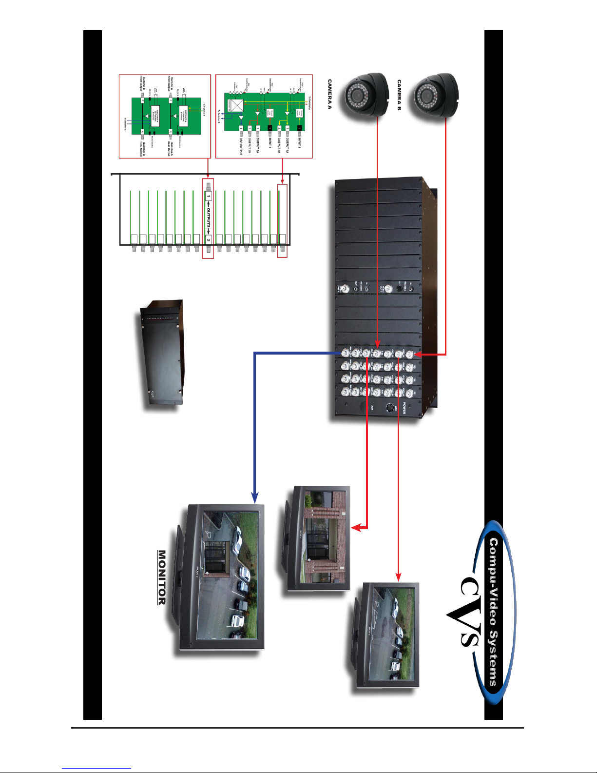
DSPA-1612
(16)2x1 Video Screen Splitter
MONITOR
Front View
Input
Input
Output 1 Camera B
Output 1 Camera A
Split Screen Output
CAMERA A
CAMERA B
Tel: (845) 737-7009 • Fax: (845) 737-0426 • Web: www.compuvideosystems.com
Page 23

Compu-Video Systems Inc. warrants this product and all accessories provided with it to be free of
defects in material and workmanship for a period of 5 years from the ORIGINAL date of purchase.
A Purchase receipt or other proof of date of original purchase from Compu-Video Systems Inc. or one
of its Authorized Distributors or Dealers will be required before warranty service is rendered.
Compu-Video Systems reserves the right to audit any claim and to nullify any claim that cannot be
substantiated.
Serial Numbers that have been altered, defaced or removed void this warranty.
This warranty only covers failures due to defect in materials or workmanship, which occur during
normal use. The warranty does not cover damage which occur in shipping of failures which result
from but not limited to faulty installation, set-up adjustments, maladjustment of user controls, improper
operation, power line surge, improper voltage supply, lightning damage, modication, or damage that
is attributed to acts of God or force majeure.
Compu-Video Systems does not warrant, and shall not be responsible for, any lost data or images,
regardless of the cause of the loss. They shall also not be responsible for any costs associated with
removing and installing Compu-Video Systems products.
HOW THE WARRANTY WORKS
If this product, or any of the accessories supplied with it, become defective within the warranty period,
and it is determined that the repair is covered under the warranty Compu-Video Systems Inc. will
repair the product without charge. Overland return transportation from Compu-Video Systems Inc. to
the user is free of charge.
HOW TO GET SERVICE
Please contact CVS by phone for a return authorization number and then return the defective unit,
transportation prepaid and a dated proof of purchase to:
Compu-Video Systems Inc.
37 Arden Drive
Garrison, NY 10524
The customer is responsible for all costs incurred from shipping the product back to Compu-Video
Systems Inc.
OBTAINING TECHNICAL HELP/SERVICE
Web Site: www.compuvideosystems.com
Phone: (845) 737-7009
Fax: (845) 737-0426
In No Event Shall Compu-Video Systems Inc. Be Liable For Consequential Damages
Some states do not allow exclusion or limitation of incidental or consequential damages, so the above
limitation may not apply to you. This warranty gives you specic legal rights, and you may also have
other rights which vary from state to state.
LIMITED WARRANTY
P.O. Box 749
Peekskill, NY 10566
Phone: (845) 737-7009
Fax: (845) 737-0426
Page 24

 Loading...