

Page 1
DA-3212
(32)1x2 Distribution Amplier
Instruction Manual
Thank you for purchasing one of our products. Please read this manual before using this
product. When using this product, always follow the instructions contained in this manual,
and pay attention to the safety information.
Page 2

Do not expose this product to water, rain or moisture.
Doing this can result in electric shock or re.
Never take this product apart or try to modify it.
Doing so is very dangerous and could result in electric shock.
Do not store this product near open ame.
Do not use this product near open ame or place lit or ammable items, such as
candles, incense, ect., on it.
Do not place any containers lled with water or other liquids near this product.
Doing so could result in re or electric shock if the liquid spills and enters the product or
gets it wet. If a liquid spills near this product, unplug the product immediately.
Do not remove or insert the power supply with wet hands.
Doing so could result in electric shock.
Do not use the power supply in any of the following ways.
Doing so could result in re or electric shock.
Modifying or heating the power cable
Damaging the power cable
Bending or tugging on the power cable unnecessarily
Knotting or kinking the power cable
Setting heavy objects on the power cable
When moving this product , rst unplug the power supply from the outlet. Do not
tug the cable or move this product with the power supply plugged into the outlet.
Doing so could damage the cable, possibly resulting in re or electric shock.
To reduce the risk of electric shock, do not remove the cover.
No parts inside the product can be serviced by the user. If your product needs service
contact:
Compu-Video Systems Inc. at (845) 737-7009.
Usage Environment
Avoid using or storing this product in areas such as those listed below. Doing so could
damage the product or cause it to malfunction.
Areas exposed to heat or ames
Humid areas and areas where water is used
Handling this product
Do not drop or apply a strong force to this product or any included or connected parts.
Do not spill liquids around or inside this product or drop ammable objects around or
inside it.
Power Supply
Only use the supplied power supply which is designed specically for this product.
Do not allow the plug to come into contact with metal or water.
This Product is not designed for contact medical use
Do not use this product for medical applications that could result in patient contact.
The information in this manual is believed to be accurate. It is intended for professional
end users having the skills to evaluate and use the data properly. Compu-Video assumes
no liability in connection with damages incurred while using this product.
P.O. Box 749 Peekskill, NY 10566 Tel: (845) 737-7009 Fax: (845) 737-0426 Web: www.compuvideosystems.com
Page 3
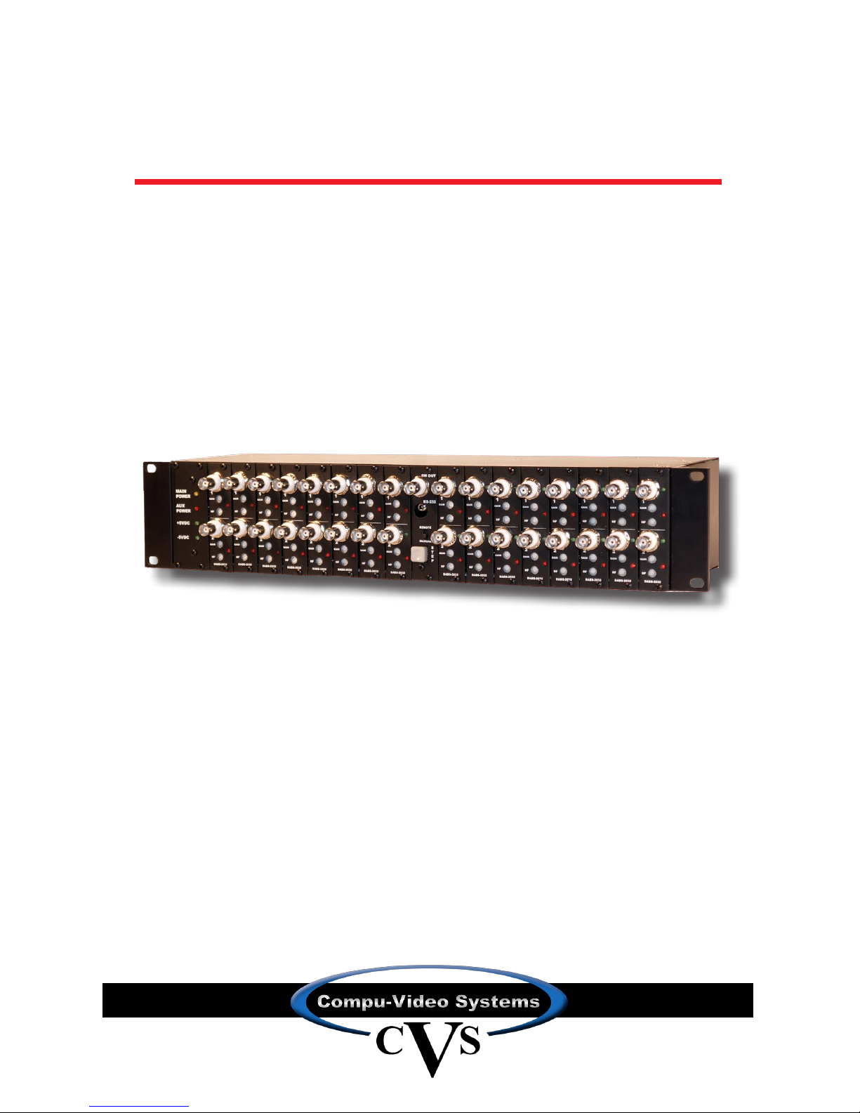
Model # Of Inputs # Of Outputs Controls Special Features
DA-3212 32 2 Per Input
Gain &
High Frequency
Ground Loop
Blocking
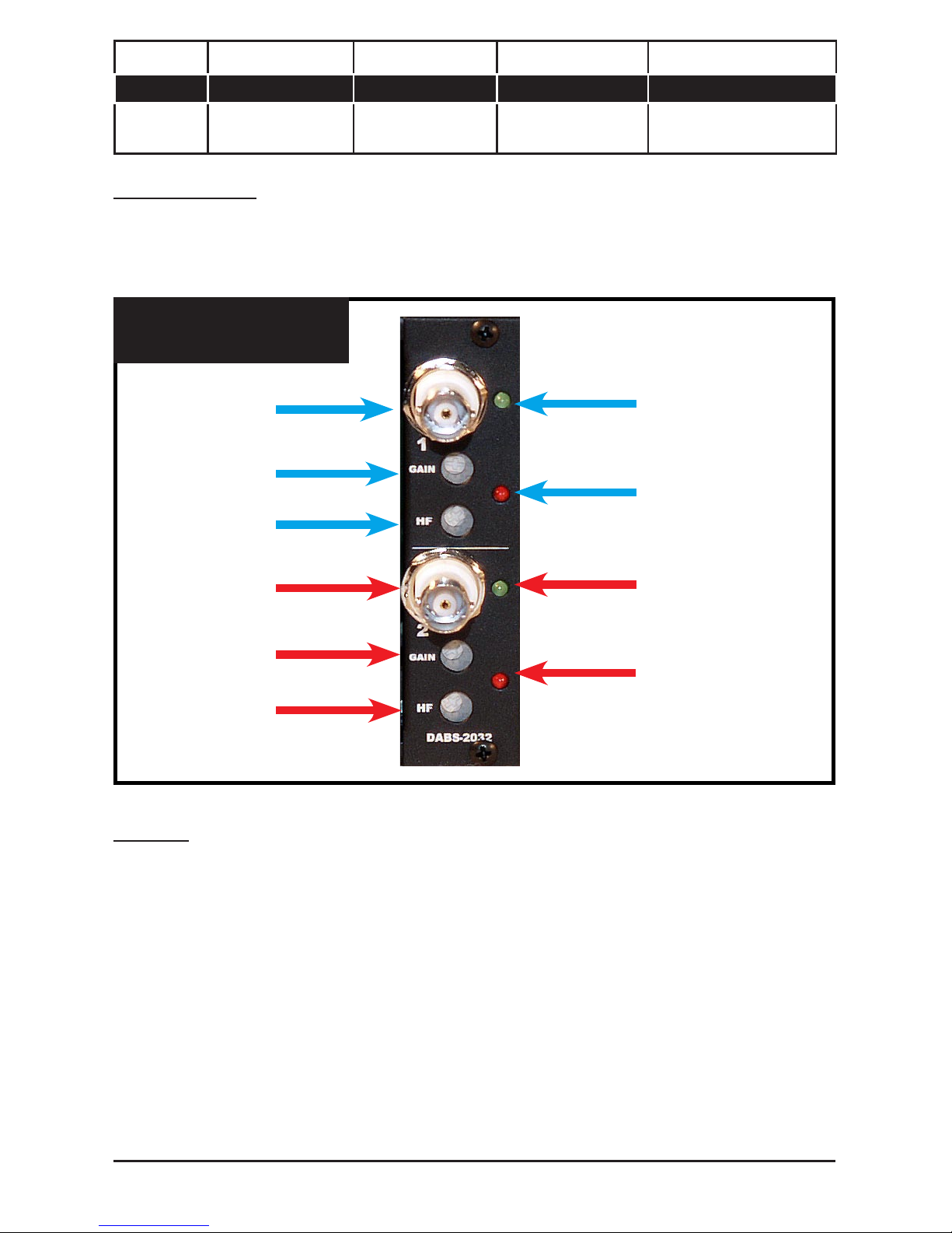
CONTROLS:
Each DABS-2032 board ( Fig. 1 ) has two sets of controls, a gain or level control and a high
frequency adjust for picture sharpness, for each video input. The green LED indicates the
presence of video and the red LED indicates which position the switcher output is viewing.
Input 1
Input 2
Gain Adj.
For Input 1
High Freq. Adj.
For Input 1
Video Present
Indecator For Input 1
Switcher Selection
For Input 1
Gain Adj.
For Input 2
High Freq. Adj.
For Input 2
Video Present
Indecator For Input 2
Switcher Selection
For Input 2
Fig. 1
Front View Of DABS-2032
NOTE:
For Board #DABS-2032-2 the gain range is extended to approx +/-6dB to compensate for
larger then normal signal level swings.
P.O. Box 749 Peekskill, NY 10566 Tel: (845) 737-7009 Fax: (845) 737-0426 Web: www.compuvideosystems.com
Page 4
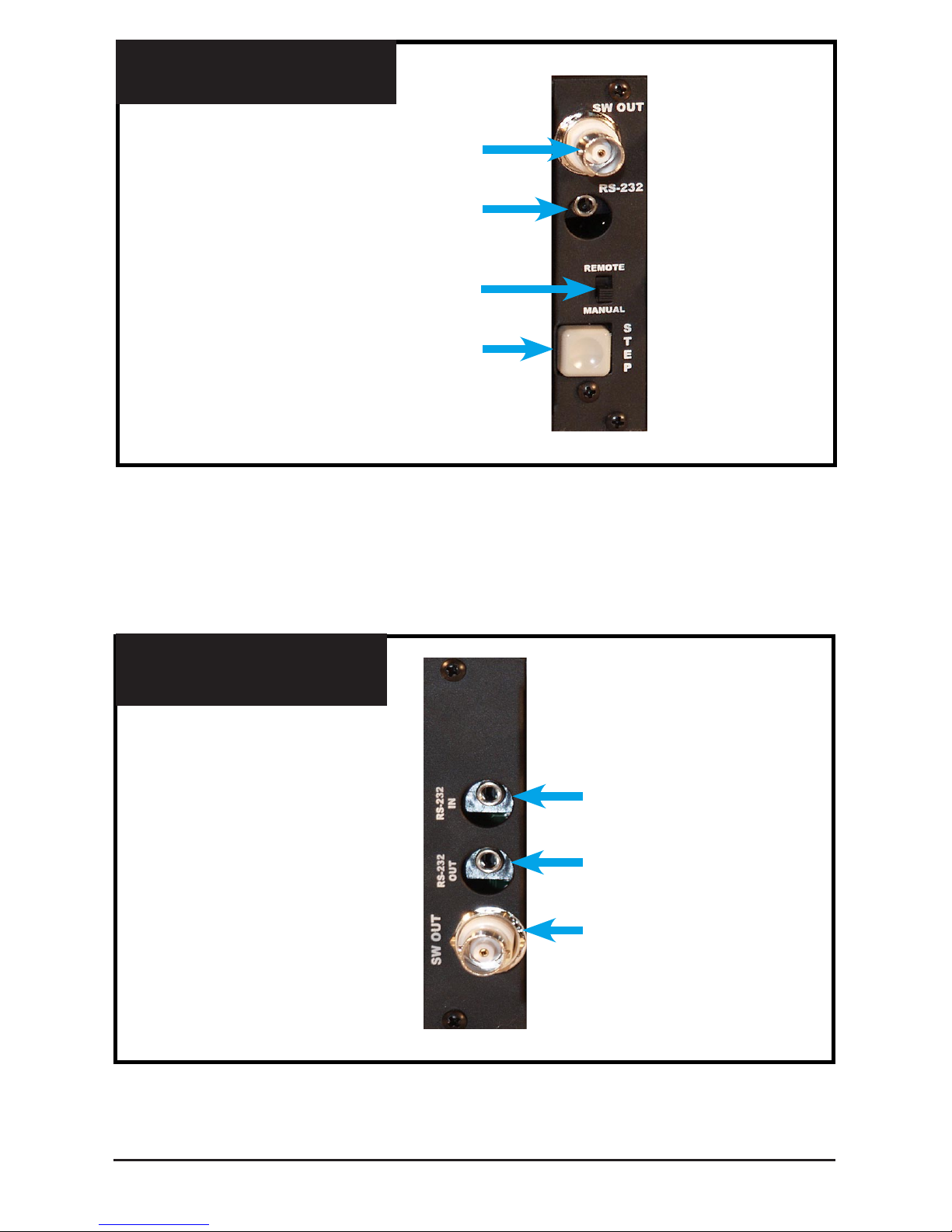
The switcher board ( Fig. 2 / Fig. 3 ) has 2 controls, a Step Switch Button, and a Remote/
Manual select for switcher control. To setup the system up, select the Manual position on
the slide switch and connect you test monitor/ equipment to switcher out 1 or 2 and using
the step button, step through each input making the needed adjustments as you go. You
can leave both switcher outputs connected at all times or you can use just the one you
need.
Switcher Output #2
Remote Input #2
Step Switch
Remote / Manual Select
Fig. 2
Front View Of Switcher Board
Switcher Output #1
Remote Input #1
Remote Output
Fig. 3
Rear View Of Switcher Board
P.O. Box 749 Peekskill, NY 10566 Tel: (845) 737-7009 Fax: (845) 737-0426 Web: www.compuvideosystems.com
Page 5
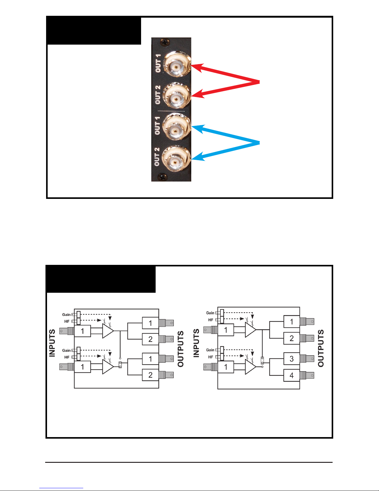
Outputs 1&2
for Input 1
Outputs 1&2
for Input 2
Fig. 4
Rear View Of DABS-2032
Under normal setup, outputs 1 and 2 are identical. If a special compensation circuit is used
for pre-emphisis, output 1 will differ from output 2. Output 2 and the switcher output will be
the same. If you select the 1x4 mode of operation all 4 outputs will display Input 1. If
pre-emphisis is selected both #1 outputs will be different from the #2, and switcher
outputs.
Fig. 5
Drawings Of 1x2 & 1x4 Modes
Shown In Changeable
(2) 1x2 Mode
Shown In Changeable
1x4 Mode
P.O. Box 749 Peekskill, NY 10566 Tel: (845) 737-7009 Fax: (845) 737-0426 Web: www.compuvideosystems.com
Page 6
P.O. Box 749 Peekskill, NY 10566 Tel: (845) 737-7009 Fax: (845) 737-0426 Web: www.compuvideosystems.com
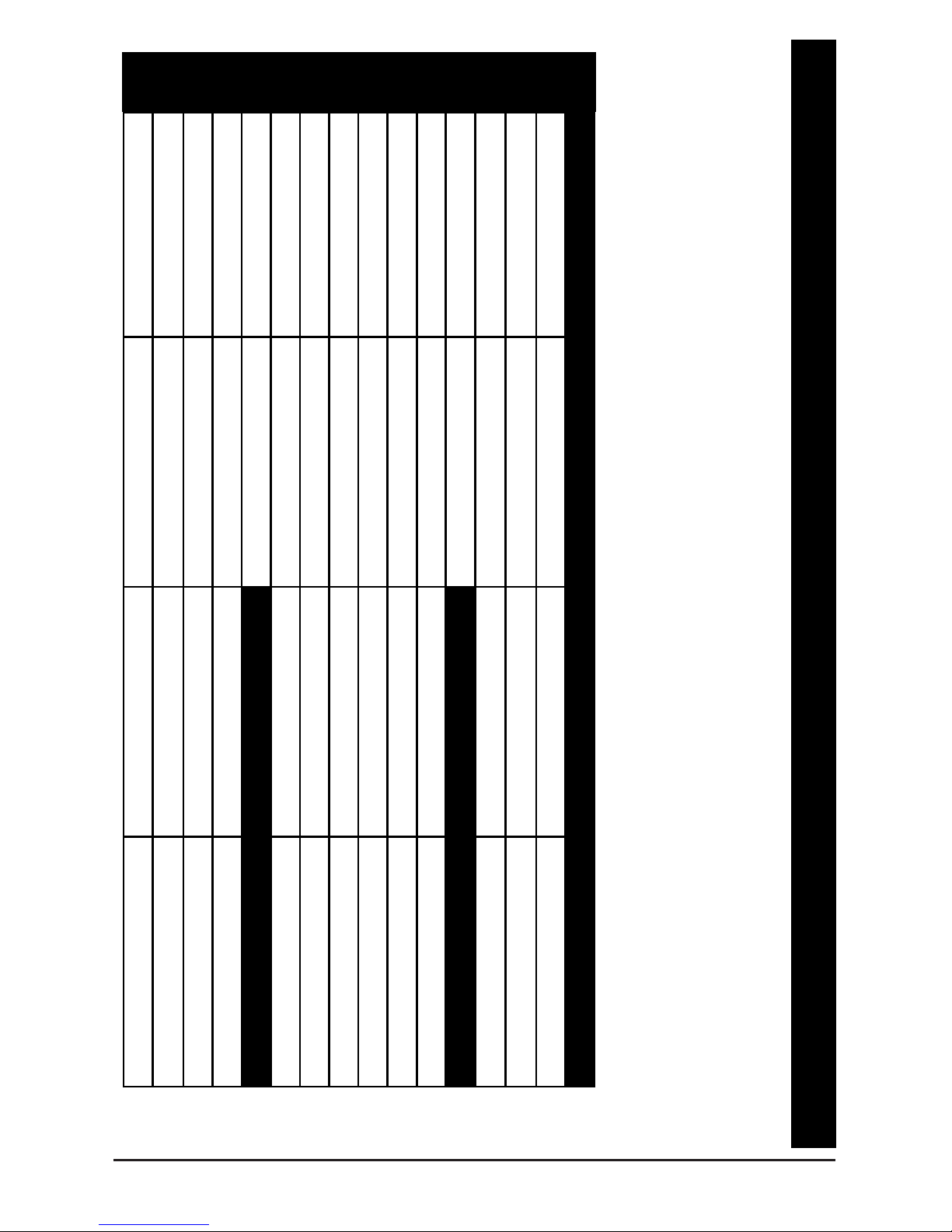
Main Power Input
Auxiliary Power Input
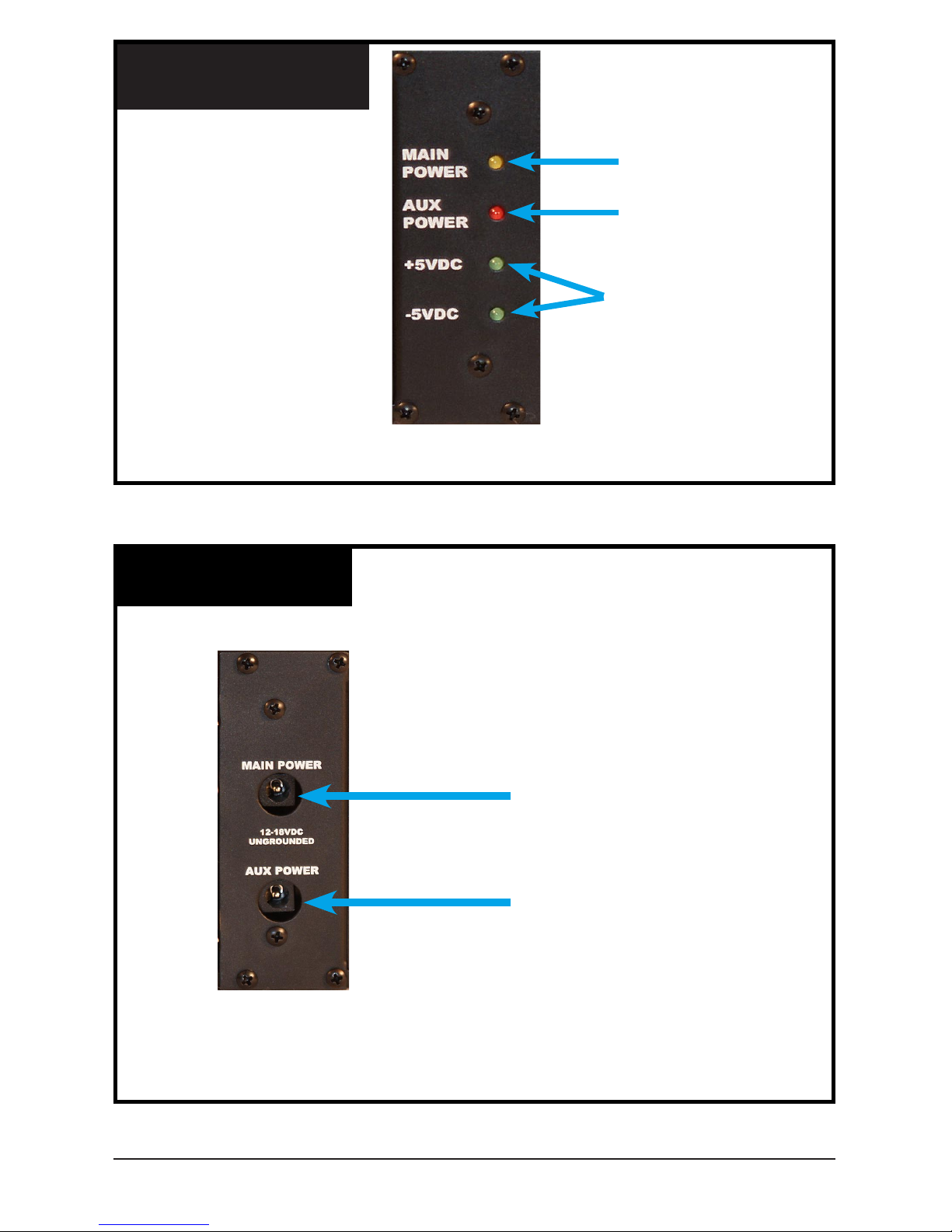
Main Power
Indecator
Aux Power
Indecator
Internal Power
Supply Indecators
Fig. 6
Front View Of Power Panel
Fig. 7
Rear View Of Power Panel
Page 7

P.O. Box 749 Peekskill, NY 10566 Tel: (845) 737-7009 Fax: (845) 737-0426 Web: www.compuvideosystems.com
Installation And Removal Of A Board Set (BS) From
The DA-3212 Chassis.
Boards can be Hot Swapped if needed but it is recommended that power be disconnected
before changing any boards.
1) Remove power from the system by unplugging the power pack(s) from the 110VAC
source.
2)Remove the 2 screws holding the desired board in the chassis
Removal of a BS:
A) Determine which board set is to be removed. Locate the BS and remove the
2 screws holding the board in place (Fig.8). Then unplug the board by gently
pulling the board towards the front of the chassis.
B) On the rear of the unit ( Fig. 9) is a matching connector board that must be
removed if a complete boards set is being changed. As there are no
electronics on the rear board you do not need to change it for repair purposes.
Locate the corresponding rear connector set, mark the connectors. Using a
small Phillips head screwdriver, remove the top and bottom screw from the
connector panel. Carefully, holding on to a connector, pull the panel away
from the rear of the chassis. Put the main board and the connector board
together.
Fig. 8
Removal Of Front Panal
Screws That Need To Be Removed
Before You Slide The Card Out
Page 8

P.O. Box 749 Peekskill, NY 10566 Tel: (845) 737-7009 Fax: (845) 737-0426 Web: www.compuvideosystems.com
Installing a Board Set in an open slot:
A) Locate the slot that the front board will be installed in. Holding the board so
that the components face left, carefully slide the board into the slot. Seat the
board in the mating connector in the motherboard. If you meet any
resistance, remove the board and check for bent pins and a misaligned
mating connector in the back of the slot. After correcting the error, reinstall
the board. Then reinstall both screws that hold the board in place.
B) On the rear of the unit you need to install the connector eld. Carefully align
the top pin on the back of the connector eld with the top pin on the internal
connector on the rear of the chassis. There may be open slots on the
connector in the chassis. After the connector panel is installed, using a small
Philips head screwdriver, install the two mounting screws in the panel.
C) Once the boards have been removed/installed you can reconnect the video
cables.
D) Reconnect the AC power and check for an LED on the video switcher
indicator or a video presence indicator. If none is visible, check you power
connections. If a problem persists, gently unplug the main board of the BS
you just installed. If the power returns, check for a misalignment when the
board is installed. If there is a shift from top to bottom you can improperly
install the boards and short the power supply. Reset the board.
E) Attach a test monitor the recently installed BS and test for proper operation.
Check for video. If none is present, check the installation of the rear
connector eld for a misalignment. Reset the rear connector panel and test
again. Align the board as specied.
If any problems persist, call 845-737-7009 and ask for tech support.
Fig. 9
Rear View Of DABS-2032
Screws That Need To Be Removed
Before You Slide The Card Out
Page 9

P.O. Box 749 Peekskill, NY 10566 Tel: (845) 737-7009 Fax: (845) 737-0426 Web: www.compuvideosystems.com
Fig. 11
Multi System Diagram
RS-232 Switcher Wiring Diagram
7
5
3
2
Tip Or Center Pin
Ring Or Shield
25 Pin D Type
Connector
9 Pin D Type
Connector
Use For DA-3212
3.5mm
Fig. 10
RS -232 Cable Diagram
Machine 1
Machine 2
Video
Video
Video
CS-1600
Master
RS-232
RS-232
RS-232
See CS-1600 manual
for connector type
requirements.
Page 10

P.O. Box 749 Peekskill, NY 10566 Tel: (845) 737-7009 Fax: (845) 737-0426 Web: www.compuvideosystems.com
Fig. 12
Single Unt Diagram
Fig. 13
Master Slave Diagram
Master Slave Suitcase Jumper
8 pos Dip Switch
Video
RS-232
Move jumper to the right
to place in slave position
Page 11

P.O. Box 749 Peekskill, NY 10566 Tel: (845) 737-7009 Fax: (845) 737-0426 Web: www.compuvideosystems.com
Fig. 14
Master / Slave Unit Setup
3.5mm stereo Audio
Male To Male Cable
Out From Back Only
In From Front Or Back
Out From Back Only
In From Front Or Back
DB9 / 25 To 3.5mm Phono
See Fig. 10
Page 12

P.O. Box 749 Peekskill, NY 10566 Tel: (845) 737-7009 Fax: (845) 737-0426 Web: www.compuvideosystems.com
MULTI-SWITCHER SETUP:
A CS-1600 can be used as a master switcher to be fed by the DA-3212 slave switchers,
or a DA-3212 can be set up as a master if desired. To connect multiple units together to
enlarge the number of inputs you must set the slave units up for the proper addresses.
A) Determine which unit will be the master. All units are preset as masters from the
factory. Put it aside.
B) On each of the slave units:
Disconnect the power to the unit.
Remove the switcher card
Using the master slave diagram Fig. 13, locate:
The Master/slave suitcase jumper
The 8 pos Dip switch
C) Determine the ID number to be used for each slave unit,
(i.e. unit 16, or 15 or 14....). Mark the unit as to the ID number it is set for. Written in
pencil on the bottom will do the trick!
D) Set the suitcase jumper to the Slave position as shown in the master slave jumper
setup diagram.
E) Set dip switch #5 to the off position.
There is an eight position dip switch located on the control board. It is factory set for
machine #1 and the suitcase jumper is set for a master unit. To add addition units you will
start at the highest number and count down as shown in the system diagram. The master
will always be machine 1 unless there are 16 slave units. The slaves will start at 16 and go
down to 1 as they are added.
SWITCH CODE
SWITCH
MACHINE NUMBER
4 3 2 1
0000 ON ON ON ON 1
0001 ON ON ON OFF 2
0010 ON ON OFF ON 3
0011 ON ON OFF OFF 4
0100 ON OFF ON ON 5
0101 ON OFF ON OFF 6
0110 ON OFF OFF ON 7
0111 ON OFF OFF OFF 8
1000 OFF ON ON ON 9
1001 OFF ON ON OFF 10
1010 OFF ON OFF ON 11
1011 OFF ON OFF OFF 12
1100 OFF OFF ON ON 13
1101 OFF OFF ON OFF 14
1110 OFF OFF OFF ON 15
1111 OFF OFF OFF OFF 16
Page 13

APPENDIX I
Command Protocol For RS-232 Port - IBM PC Type
10 CLS
15 LET E% = E%+1
30 PRINT”SELECT THE NUMBER OF THE SWITCHER TO BE CHANGED [1 TO 16]”;
40 INPUT A%
50 IF A% = 1 THEN LET A$ = ” ` ”
60 IF A% = 2 THEN LET A$ = ” a ”
70 IF A% = 3 THEN LET A$ = ” b ”
71 IF A% = 4 THEN LET A$ = ” c ”
72 IF A% = 5 THEN LET A$ = ” d ”
73 IF A% = 6 THEN LET A$ = ” e ”
74 IF A% = 7 THEN LET A$ = ” f ”
75 IF A% = 8 THEN LET A$ = ” g ”
76 IF A% = 9 THEN LET A$ = ” h ”
77 IF A% = 10 THEN LET A$ = ” i ”
78 IF A% = 11 THEN LET A$ = ” j ”
79 IF A% = 12 THEN LET A$ = ” k ”
80 IF A% = 13 THEN LET A$ = ” l ”
81 IF A% = 14 THEN LET A$ = ” m ”
82 IF A% = 15 THEN LET A$ = ” n ”
83 IF A% = 16 THEN LET A$ = ” o ”
100 PRINT ” SELECT INPUT TO BE CHANGED [1 - 32] ” ;
103 INPUT Y%
500 IF Y% = 1 THEN LET B$ = ” 0 ”
510 IF Y% = 2 THEN LET B$ = ” 1 ”
520 IF Y% = 3 THEN LET B$ = ” 2 ”
530 IF Y% = 4 THEN LET B$ = ” 3 ”
600 IF Y% = 5 THEN LET B$ = ” 4 ”
610 IF Y% = 6 THEN LET B$ = ” 5 ”
620 IF Y% = 7 THEN LET B$ = ” 6 ”
630 IF Y% = 8 THEN LET B$ = ” 7 ”
700 IF Y% = 9 THEN LET B$ = ” 8 ”
710 IF Y% = 10 THEN LET B$ = ” 9 ”
720 IF Y% = 11 THEN LET B$ = ” : ”
730 IF Y% = 12 THEN LET B$ = ” ; ”
800 IF Y% = 13 THEN LET B$ = ” < ”
810 IF Y% = 14 THEN LET B$ = ” = ”
820 IF Y% = 15 THEN LET B$ = ” > ”
830 IF Y% = 16 THEN LET B$ = ” ? ”
831 IF Y% = 17 THEN LET B$ = “ @ ”
The following is an example of a GW basic program used to control from 1 to 16 DA-3212s.
The factory preset is machine #1, whose command is on line 910. The rst group of
characters are used to determine which machine number is being activated in a multi
switcher system. Normally machine #1 is used a default. The second group determines the
Input that will be switched to the output once the commands are sent. Line #905 represents
the settings for the RS-232 Com. port. If you have any questions please call Compu-Video
Systems at (845) 737-7009 between the hours of 9am and 5pm (EST).
P.O. Box 749 Peekskill, NY 10566 Tel: (845) 737-7009 Fax: (845) 737-0426 Web: www.compuvideosystems.com
Page 14

832 IF Y% = 18 THEN LET B$ = “ A “
833 IF Y% = 19 THEN LET B$ = “ B “
834 IF Y% = 20 THEN LET B$ = “ C “
835 IF Y% = 21 THEN LET B$ = “ D “
836 IF Y% = 22 THEN LET B$ = “ E “
837 IF Y% = 23 THEN LET B$ = “ F “
838 IF Y% = 24 THEN LET B$ = “ G “
839 IF Y% = 25 THEN LET B$ = “ H “
840 IF Y% = 26 THEN LET B$ = “ I “
841 IF Y% = 27 THEN LET B$ = “ J “
842 IF Y% = 28 THEN LET B$ = “ K “
843 IF Y% = 29 THEN LET B$ = “ L “
844 IF Y% = 30 THEN LET B$ = “ M “
845 IF Y% = 31 THEN LET B$ = “ N “
846 IF Y% = 32 THEN LET B$ = “ O “
900 GOTO 905
905 OPEN “COM1:9600,N,8,1,RS,CS,DS,CD,BIN” AS #1
910 PRINT #1, A$ ; B$ ;
920 CLOSE #1
930 CLS
931 INPUT “DO YOU WISH TO EXIT THE DA-3212 PROGRAM [YES / NO]” ; A$
932 IF A$ = ”Y” THEN 960
933 IF A$ = ”y” THEN 960
934 IF A$ = ”N” THEN 10
935 IF A$ = ”n” THEN 10
960 CLS
962 END
A$ is the machine number on line 910
B$ is the input number on line 910
P.O. Box 749 Peekskill, NY 10566 Tel: (845) 737-7009 Fax: (845) 737-0426 Web: www.compuvideosystems.com
Page 15

P.O. Box 749 Peekskill, NY 10566 Tel: (845) 737-7009 Fax: (845) 737-0426 Web: www.compuvideosystems.com
Application Notes (Coax):
Page 16

P.O. Box 749 Peekskill, NY 10566 Tel: (845) 737-7009 Fax: (845) 737-0426 Web: www.compuvideosystems.com
Application Notes CDA-202 / CDA-202 RG45:
Page 17

RJ-45 Jack
PIN COLOR FUNCTION
1 White-Orange S2
2 Orange S1
3 White-Green Audio (+)
4 Blue A1
5 White-Blue A2
6 Green Audio (-)
7 White-Brown Video (+)
8 Brown Video (-)
NOTE: Pins 1-6 Are NOT Used With This product!
For Unit With RJ-45 Input Connectors Use:
•Pin 7 For Video (+) (Wire: White-Brown)
•Pin 8 For Video (-) (Wire: Brown)
CDABS Series Of Boards
CDA-202-RJ45 / CDABS-1432-RJ45
STANDARD CAT-5 CONNECTORS
CDA-1432
CDA-202
Pair 1
Pair 3
Pair 4
Pair 2
Jack Position
1 2 3 4 5 6 7 8
W-O O W-G BL W-BL G W-BR BR
The CDABS-1432 and the DABS-1432 are 1x4
DA cards with Gain, HF Adj., Ground Loop
Blocking Inputs, and Surge Suppression.
CDABS-1432: 1 CAT-5 input and 4 BNC outputs
DABS-1432: 1 BNC input and 4 BNC outputs
P.O. Box 749 Peekskill, NY 10566 Tel: (845) 737-7009 Fax: (845) 737-0426 Web: www.compuvideosystems.com
Page 18
DA-3212 Multi Input Cable Comp. DA
The DA-3212 consists of a CH-3212 card frame system and (16) DABS-2032. Each card has (2) 1x2 adjustable cable compensating
ampliers with ground loop blocking, surge protected inputs. The DA-3212 includes a built in 32 pos. sequential, RS-232 controllable
switcher which can be operated locally, with an optional remote control unit or a computer. For 1x1 operation use only the output needed and
simply leave the unused one unterminated or each board can be congured for 1x4 operation. Output 1 of each channel can be custom “pre
emphasized” for driving long cable distances. On the front of the unit in addition to the video inputs, you will nd the switcher output, remote
switcher control input, local switcher controls, indicators and video presence indicators for each input. The individual I/O boards are
interchangeable through the front of the unit. The DA-3212 has 2 power supply inputs for optional power back up. Optional terminal strip
power input connectors for Din rail type power sources are available
Video:
Inputs: Composite Video High Frequency Boost: Typ. 0-+10dB
Input Connectors: BNC Cable Compensation: Typ. .5-+15dB
Max Input Level: 2.0VPP Into 75ohms CCMR: Typ. 60dB @ 4mHz
Input Impedance: 75ohm +/-5% Isolated BNC)
Power Requirements:
ESD Protection: +/- 15KV air, +/-8KV contact DC Operation: 12 to 18VDC Isolated Source
Outputs: 2x Power Supply: (1) CVT-12500 Included
Output Connectors: BNC AC Power: 120VAC
Output Impedance: 75ohm +/-5% AC Power Draw: <13w
Gain In/Out: Var to +5.0dB Power Connector: 2.5mm Coax (2x)
Diff. Gain: <.5% Optional: 2 Pos. Term. Strip (2x)
Diff. Phase: <.5°
Mechanical:
Frequency Response: 0-30mHz +/- .5dB Size: 19”W x 8”D x 3.5”H
Power Supply Hum: <63dB Weight: <15lbs
H Tilt: <1% Environment: 0-70°C
V Tilt: <1% Optional Remote Control: CTS-3200
S
P
E
C
I
F
I
C
A
T
I
O
N
S
P.O. Box 749 Peekskill, NY 10566 Tel: (845) 737-7009 Fax: (845) 737-0426 Web: www.compuvideosystems.com
Page 19

LIMITED WARRANTY:
Compu-Video Systems warrants this product and all accessories provided with it to be
free of defects in material and workmanship for a period of 5 years after the original date
of purchase. This warranty does not cover damage to the product resulting from accident,
misuse or modication.
How The Warranty Works
If this product, or any of the accessories supplied with it, become defective within the
warranty period, Compu-Video Systems Inc. will at its discretion repair, or replace the
product with an equivalent unit of equal or higher value without charge. Overland return
transportation from Compu-Video Systems Inc. to the user is free of charge.
How To Get Service
Please contact CVS by phone for return authorization number and then return the
defective unit, transportation prepaid and a dated proof of purchase to:
Compu-Video Systems Inc.
37 Arden Drive
Garrison, NY 10524
The customer is responsible for all costs incurred from shipping the product back to
Compu-Video Systems.
Obtaining Technical Help/Service
Web Site: www.compuvideosystems.com
Phone: (845) 737-7009
Fax: (845) 737-0426
In no event shall Compu-Video Systems Inc.
be liable for Consequential Damages.
Some states do not allow exclusion or limitation of incidental or consequential damages,
so the above limitation may not apply to you. This warranty gives you specic legal rights,
and you may also have other rights which vary from state to state.
P.O. Box 749 Peekskill, NY 10566 Tel: (845) 737-7009 Fax: (845) 737-0426 Web: www.compuvideosystems.com
Page 20

 Loading...