

Page 1
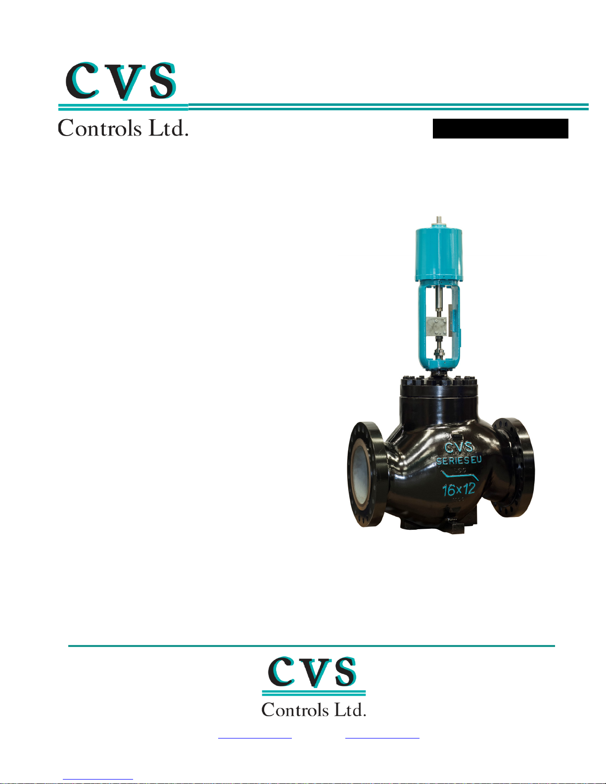
CVS Controls Series 470
INSTRUCTION MANUAL
Head Office
Website: www.cvs-controls.com Email: info@cvs-controls.com
Piston Actuators
The CVS Series 470 is a double acting
pneumatic Piston Actuator, suitable
for use with Globe, Angle, Three Way,
and Reverse acting valves as well as
Steam Equipment. Capable of high
thrust applications to 19,500 lb-f,
with a maximum travel to 8 1/8
inches.
The CVS Series 470 Actuator may be
used in on/off applications, as well as
throttling service when used with a
positioner.
3900 101 Street
Edmonton, Alberta
T6E 0A5
Canad
a
ffice: (780) 437-3055
O
Fax: (780) 436-5461
Calgary Sales Office
3516 114 Avenue SE
Calgary, Alberta
T2Z 3V6
Canada
Office: (403) 250-1416
Fax: (403) 291-9487
Page 2

CVS Series 470 Piston Actuator – Specifications:
Model
Maximum Travel (in)
Piston Area (in2)
CVS 471-16-80
8 1/8
88.5
CVS 471-16-100
8 1/8
130.5
Stem Diameter (in)
Max allowable
Thrust*
Cast
Yoke**
Steel
Yoke
CVS 471-16-80
5
1 1/4
13200
13200
CVS 471-16-100
5
1 1/4
17000
19500
*reduce max thrust by 10% if using a positioner
** Cast Iron Yoke Standard
Standard Input: 3-15psig, 6-30psig or split range
Maximum Cylinder Pressure: 125psig, (*not to exceed max allowable thrust)
Temperature Rating: -30
o
F to 175oF, standard with Nitrile O-Rings
Material Specifications (Standard):
Yoke: Cast Iron (standard) or WCB Steel (optional)
Cylinder and Piston: Aluminum
Seal Bushings: Brass
O-Rings: Nitrile
Other materials may be available upon request, please contact a CVS Controls
representative for more information.
Maximum Travel and Piston Area:
Specifications and Maximum Allowable Thrust:
Model
The CVS 471 Piston Actuator operates by pneumatic air loading pressure to one side of the
piston, and unloading the opposing side. Because no positioner is included, a loading device
such as a 4 way switch valve must be installed if no additional positioner has been ordered for
use in conjunction with the CVS 471 Actuator.
Yoke Boss Diameter
(in)
2 | Page
Page 3
CVS Series 470 Piston Actuator – Installation
CVS 471 Piston Actuator
Note: Ensure proper safety procedures are followed to avoid personal injury or property
damage.
CVS 471 Piston Actuator Installation
The CVS 471 Actuator should be installed in a location which will allow adequate room for
service, maintenance and removal if required.
1. Mounting of the CVS 471 Actuator is achieved by using the 8 supplied nuts and bolts,
rather than a yoke locknut. Although the actuator may be mounted in any position,
typical installation is with the CVS 471 in the vertical position above the control valve.
2. Stem connections should be made to clamp the actuator stem and valve plug stem
together to ensure proper travel of the valve.
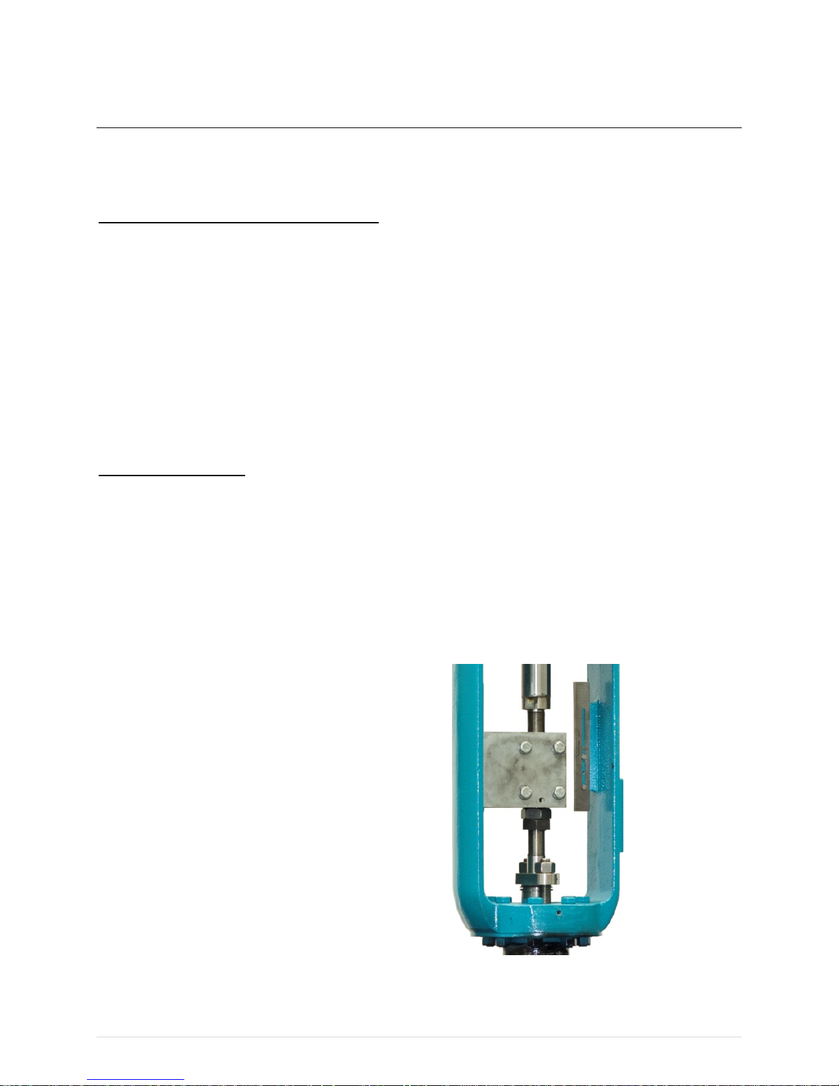
Stem Connections:
Note: Do not rotate the valve plug once it is seated to avoid damage to seating surface. Use
proper tools to avoid damaging the valve plug stem during travel adjustments. Should the stem
connections not be made properly in the stem connector, thread damage, or improper
operation may occur. The amount of each stem pressed in the stem connector should be equal
to or greater than the diameter of the stem itself. DO NOT loosen the stem connector cap
screws unless all pressure or force has been removed from the stems.
Typical Stem Connection
3 | Page
Page 4

CVS Series 470 Piston Actuator – Installation
Push Down to Close Installation – Direct Acting Valves:
1. After installation of the CVS 471 Actuator to the control valve set the actuator to the top of
its stroke and ensure the valve plug is in the closed position. Install two valve stem
locknuts, as well as travel indicator disc (if used) all the way onto the stem threads.
2. Apply pressure to the actuator until the piston rod of the CVS 471 has moved down from
the top of its stroke to the correct valve travel required.
3. Attach the Stem Connector to the Piston Rod and Valve Stem, tighten the 4 hex bolts once
in position.
4. Raise the stem locknuts and travel disc (if used) and secure against the bottom of the stem
connector.
5. Once the Stem Connector is secured, cycle the CVS 471 Actuator to verify the required
total travel settings are met, and that the valve plug seats properly before the actuator
makes contact with the lower travel stop adjustment.
Adjustments if needed:
Should minor travel adjustments be necessary, loosen the hex bolts slightly on the stem
connector. Tighten the stem locknuts together and make minor adjustments by turning the
valve stem into or out of the stem connector as needed using a wrench on the stem locknuts.
For major adjustments, repeat the stem connection of the valve and actuator as listed above.
6. After required travel has been achieved, secure the Stem Connector hex bolts. Lock the
stem locknuts against the Stem connector. Finally, adjust the actuators travel scale on the
yoke to reflect the correct valve position.
7. Using a gauge to measure the pressure to the actuator, make final adjustments to the
actuator, or positioner if used, setting the start and end points of travel for the required
instrument range.
4 | Page
Page 5

CVS Series 470 Piston Actuator – Installation
Push Down to Open Installation – Reverse Acting Valves:
1. Once the CVS 471 actuator is installed, pressure the actuator in order to cycle the Piston
Rod to the extreme upward position. Reverse loading pressure to move the Piston Rod
lower approximately 1/8”.
2. Raise the valve stem upwards in order to seat the valve plug.
3. Attach the Stem Connector to the valve stem and piston rod. Tighten the 4 Stem connector
hex bolts.
4. If a travel indicator disc, raise it to the stem connector and secure with the stem locking
nuts. The travel indicator should point to show the valve being in the open position, with
the actuator piston at the bottom of its stroke. Make adjustments to the travel indicator
scale as needed to properly show the valve position as needed.
5. Once the Stem Connector is secured, cycle the CVS 471 Actuator to verify the required
total travel settings are met, and that the valve plug seats properly before the actuator
makes contact with the lower travel stop adjustment.
Adjustments if needed:
Should minor travel adjustments be necessary, loosen the hex bolts slightly on the stem
connector. Tighten the stem locknuts together and make minor adjustments by turning the
valve stem into or out of the stem connector as needed using a wrench on the stem locknuts.
6. After required travel has been achieved, secure the Stem Connector hex bolts. Lock the
stem locknuts against the Stem connector. Finally, adjust the actuators travel scale on the
yoke to reflect the correct valve position.
7. Using a gauge to measure the pressure to the actuator, make final adjustments to the
actuator, or positioner if used, setting the start and end points of travel for the required
instrument range.
5 | Page
Page 6

CVS Series 470 Piston Actuator – Inspection and Maintenance
Certain operating conditions may require increased inspection and maintenance intervals.
Note: Ensure proper Safety and Lockout procedures are followed prior to inspection.
Relieve all pressure to the actuator and disconnect air supply line to avoid sudden open or
close action of the valve.
Shut off process to the valve or use bypass to isolate and relieve process from both sides of
the valve installation.
1. Verify the control valve is bypassed, pressure is relieved, and proper safety procedures are
followed.
2. Remove the stem connector.
3. Remove the Socket Head Cap Screws connecting the Piston Cylinder to the Piston Cylinder
Flange.
4. Remove the cylinder from the cylinder flange. It may be necessary to use a flathead
screwdriver or similar to pry the connection, once all cap screws have been removed.
5. The Piston and Piston Rod should be able to be removed with the Piston Cylinder when
lifting off of the Cylinder Flange. Once removed the Piston and Rod may be pulled out of
the Piston Cylinders open end. Take caution to not score or damage the cylinder walls.
6. Remove the Upper and Lower Seal Bushings. The Upper Seal Bushing is located at the top
end of the Piston Cylinder, the Lower Seal Bushing is located on the top end of the actuator
yoke.
Once disassembled, inspect all components for excessive wear or damage. Replace worn
O-Rings as required, lubricate with Lubriplate Mag-1 or equivalent.
Reassembly: in order to reassemble the Piston Rod Extension after removal from the Piston
Rod, clean the threads and inspect for visible damage, replace if necessary. Apply Loctite 242
or equivalent thread sealant. The torque value for the Piston rod Extension it 150 ft/lbs .
Reassemble the CVS 471 Actuator in reverse order as described above.
Contact a CVS Controls Ltd. representative for more information or to order spare parts as
required.
6 | Page
Page 7
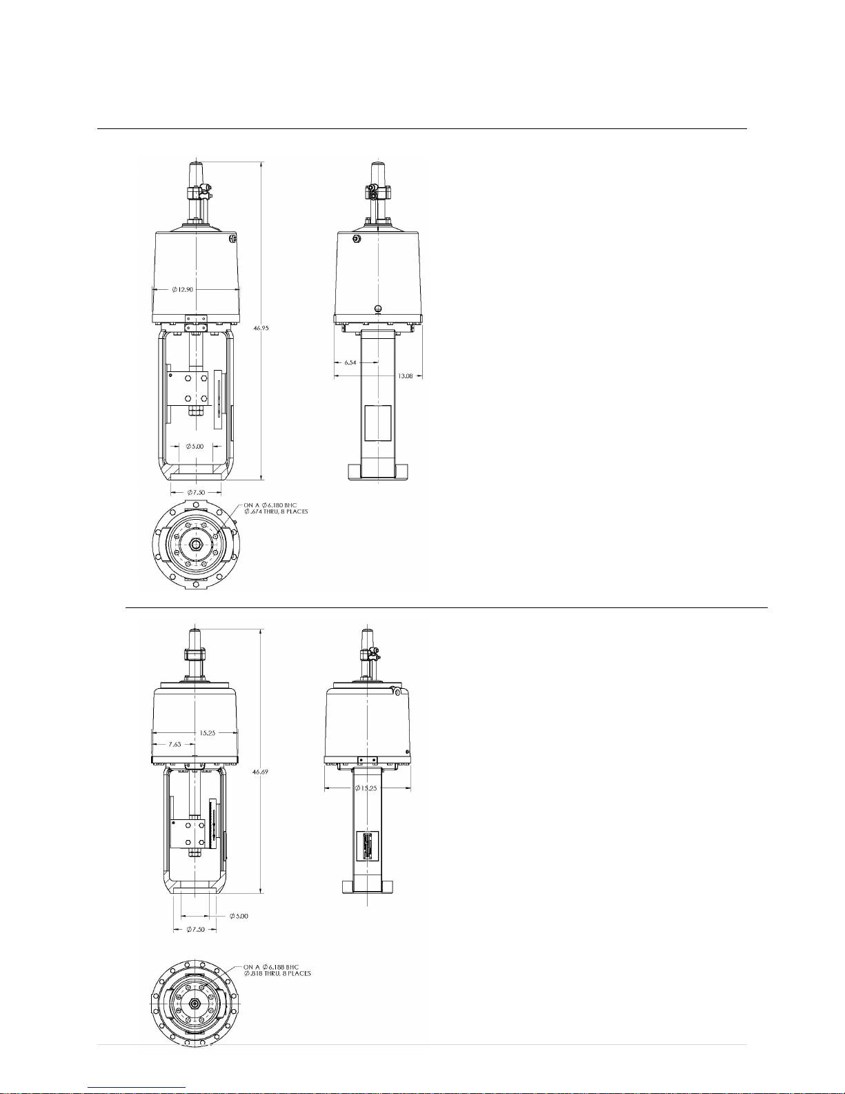
CVS Series 470 Piston Actuator – Dimensions (inches)
CVS 471-16 Size 80
CVS 471-16 Size 100
7 | Page
Page 8

CVS Series 470 Piston Actuator – Assembly
CVS 471-16 Size 80:
8 | Page
Page 9

CVS Series 470 Piston Actuator – Assembly
Item Number
Part Number
Description
Quantity
1
CVS 2R853346582
Piston Rod Extension
1
2
CVS 1H865114042
Upper Seal Bushing
1
3
CVS 1D348306992
O-Ring, Nitrile
1
4
CVS 1E736906992
O-Ring, Nitrile
1
5
CVS 1P3957X0012
Spring Retainer Spacer
1
6
CVS 1H862 506992
O-Ring1 7
CVS 2H873707062
Piston 1 8
CVS 1H862506962
O-Ring1 9
CVS 1A771132982
Cap Screw
10
10
CVS 20A6353X012
Cylinder Flange
1
11
CVS 1A485724052
Cap Screw
4
12
CVS 10A6354X012
Stem Connector
1
13
CVS 470A008
Travel Indicator Scale
1
14
CVS 1A343128982
Screw 2 15
CVS 0W073524122
Hex Nut 2 16
CVS 1H8909X0012
Spring Retainer
1
17
CVS 1A649528992
Pipe Plug
1
18
CVS 1H872024102
Piston Nut
1
19
CVS 1H862706992
O-Ring1 20
CVS 1C334206992
O-Ring
1
21
CVS 1L249718992
Elbow
1
22
CVS 1H866017012
Cylinder Tubing
1
23
CVS 1R945614042
Lower Seal Bushing
1
24
CVS 30A6352X012
Yoke 1 25
CVS 1H863538992
Name Plate
1
26
CVS 1A368228982
Drive Screw
4
CVS 471-16 Size 80:
9 | Page
Page 10

CVS Series 470 Piston Actuator – Assembly
238
Apply Lubriplate Mag-1, or equivalent
239
Apply Loctite 242, or equivalent
CVS 471-16 Size 100:
10 | Page
Page 11

CVS Series 470 Piston Actuator – Assembly
Item Number
Part Number
Description
Quantity
1
CVS 32A1321X012
Yoke, D65-45-12
1
2
CVS 2R8514X0012
Piston Rod, 416 SST, Cr-pl
1
3
CVS 10A6354X012
Connecting Block, 1018
1
4
CVS 1R945614042
Lower Seal Bushing, Brass C36000
1
5
CVS 1A771132982
Cap Screw, 1/2-13 X 2.13
16
6
CVS 32A1322X012
Cylinder Flange, D65-45-12
1
7
CVS 1U181124012
Travel Stop, Steel
1
8*
CVS 1H862606992
O-Ring, Nitrile
2
9
CVS 3U8248000A2
Cylinder Assembly
1
10*
CVS 1E736906992
O-Ring, Nitrile
1
11
CVS 1A344924052
Cap Screw, Steel, pl, 3/8-16 X 1.00
4
12
CVS 2R8537X0022
Positioner Extension, AL356.0 T6
1
13
CVS 2R853346582
Piston Rod Extension, 416 SST
1
14
CVS 2H888507062
Cylinder Cover, AL356.0 T6
1
15*
CVS 1C853806992
O-Ring, Nitrile
2
16
CVS 2R8537X0012
Insert, 6061 T6
2
17
CVS 1A649528992
Pipe Plug, 1/4 NPT
3
18*
CVS 1D348306992
O-Ring, Nitrile
1
19
CVS 1H865114042
Upper Seal Bushing, Brass C36000
1
20
CVS 1H872024102
Piston Nut, Steel
1
21
CVS 2H873707062
Piston, AL356.0 T6
1
22*
CVS 1H862706992
O-Ring, Nitrile
1
23*
CVS 1C334206992
O-Ring, Nitrile
1
24
CVS 1R281124052
Cap Screw, 9-16-12 X 1.50
8
25*
CVS 1R946499012
Wiper Scraper, SKF504272
1
26
CVS 2R851338982
Travel Indicator Scale, 302 SST
1
27
CVS 1A368228982
Drive Screw, 302 SST, .13 X .20
4
28
CVS 18A5089X0A2
Name Plate, 302 SST
1
29
CVS 1A343128982
Screw, 10-24 X .50
2
30
CVS 0W073524122
Hex Nut, 1 1/4
2
31
CVS 10A6358X012
Travel Indicator Disc, 302 SST
1
*Recommended Spare Parts
CVS 471-16 Size 100:
11 | Page
Page 12

Website: www.cvs-controls.com Email: info@cvs-controls.com
Head Office
September 2014
3900 101 Street
Edmonton, Alberta
T6E 0A5
Canada
Office: (780) 437-3055
Fax: (780) 436 5461
Calgary Sales Office
3516 114 Avenue SE
Calgary, Alberta
T2Z 3V6
Canada
Office: (403) 250-1416
Fax: (403) 291-9487
12 | Page
 Loading...