


GEOMETRIX™ - CUBE
(Manual Control Version)
INSTALLATION MANUAL
CE PIN NUMBER: 0558BQ5590
PIN: 160590
Appliance Type: B-11AS
Appliance Catergories: I2H, I2E, I2E+, I2L, I3P(37), I3+, I3B/P(30)
Serial Number
Please quote this serial number when contacting CVO Fire regarding warranty and spare part issues.
Important
• It is recommended, even if you have installed these appliances before, that you take the
time to read through these instructions and follow them step by step.
• The appliance is CE approved for use with Natural Gas – I2H, I2E, I2L, I2E+ and LPG I3P, I3+,
I3B/P. Check the data plate for actual appliance setting.
• This manual must be handed to the owner of the property once the appliance is
commissioned and retained onsite for operation and servicing reference.
• The appliance has a manufacturers warranty valid for 1 year from date of delivery. In order
to validate the warranty the appliance must be installed by a CORGI Engineer. The warranty
card supplied with this booklet should be completed by the CORGI Engineer and posted to :
Customer Service Dept, CVO Fire. 4 Beaumont Square, Aycliffe Industrial Park, Newton
Aycliffe. County Durham. DL5 6XN.
• Whenever contacting CVO Fire regarding the appliance please have the serial number and the
installers CORGI registration number available.

2
Contents
1 Appliance Technical Data
2 Appliance General Information
3 Warning for Fire Guards and Hearths
4 Appliance Unpacking Instructions
5 Appliance Installation Instructions
6 Appliance Commissioning Instructions
7
Appliance Start Up / Shut Down Instructions
8 Appliance Fault Diagnosis Instructions
9 Appliance Cleaning Instructions
10 Appliance Servicing Instructions
11 Appliance Spare Parts
Every appliance has been designed, manufactured and type tested to ensure that it
conforms to the current national and European DFE (decorative fuel effect gas fire)
legislation.
If you have any queries regarding these instructions or require additional technical
support or advice on the installation of our products, please contact our technical
support team on 01325 327 221.
The installer is to advise the user not to stand too close to the appliance for prolonged
periods of time and that loose clothing is particularly at risk of burning due to the
presence of an unguarded flame.
3
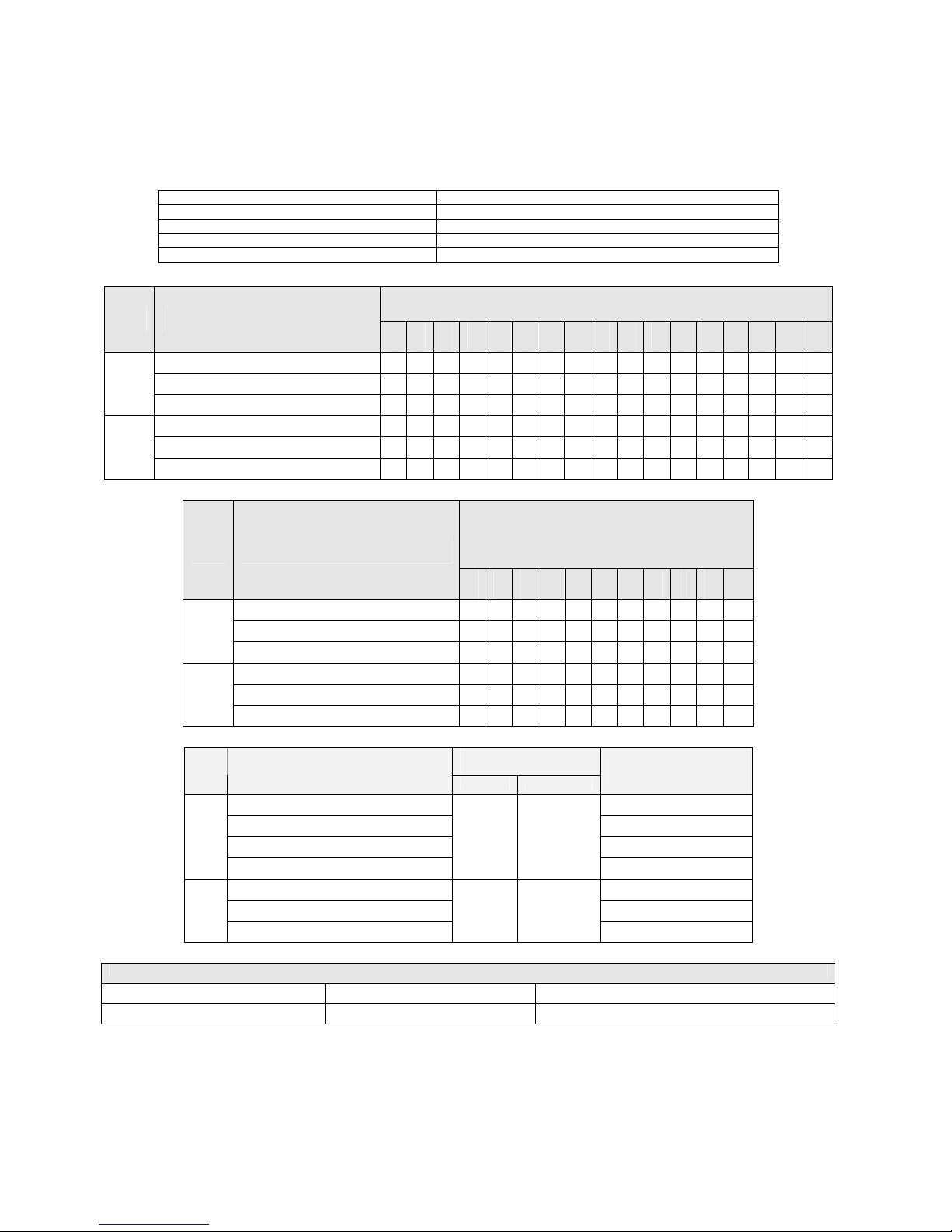
1. Appliance Technical Data
1.1. General Specification
Oxy Pilot Assembly Marking Natural Gas Burner : P4-10D , LPG Burner – P4-16
Gas Connection Size 8.0mm O.D. tubing
Minimum Flue Diameter (Millimetres/Inches) 127.0/5.0
Minimum Flue Height (metres) 3.0
Appliance Mass (kilograms) 6.4
Countries of Destination
Gas
Type
Gas Category, Type
And Supply Pressure
AT
BE
CH
CY
CZ
DE
DK
EE
ES
FI
FR
GB
GR
HU
IE
IT
LT
I2H - G20 at 20mbar
9
9
9
9 9 9 9
9 9
9 9 9
I2E - G20 at 20mbar
9
NG
I2E+ - G20'G25at20'25mbar
9
9
I3P - G31 at 37mbar
9 9
9
9
9 9 9
9 9
I3+ - G30'G31 at 28-30'37mbar
9 9 9 9
9
9 9 9
9 9
LPG
I3B/P – G30'G31 at 30mbar
9
9
9 9 9 9 9 9 9 9
9
Countries of
Destination
Gas
Type
Gas Category, Type
And Supply Pressure
LU
LV
NL
NO
PL
PT
RO
SE
Sl
SK
TR
I2H - G20 at 20mbar
9
9
9 9 9 9 9 9
I2E - G20 at 20mbar
9
9
9
NG
I2L - G25 at 25mbar
9
I3P - G31 at 37mbar
9
9 9 9
I3+ - G30'G31 at 28-30'37mbar
9
9 9
LPG
I3B/P – G30'G31 at 30mbar
9 9
9 9 9 9 9
Injector
(1 per appliance)
Gas
Type
Gas Category, Type
And Supply Pressure
Marking Size
Nominal Heat Input
kW, Gross
I2H - G20 at 20mbar
5.0
I2E - G20 at 20mbar
5.0
I2E+ - G20'G25at20'25mbar
5.0/4.6
NG
I2L - G25at 25mbar
440
Multi holed
7x0.77mm
4.6
I3P - G31 at 37mbar
4.4
I3+ - G30'G31 at 28-30'37mbar
4.4
LPG
I3B/P – G30'G31 at 30mbar
100
Single Hole
1.0mm
4.4
Recommended maximum builders opening size – If not supplied with enclosure and gather
Height, mm Width, mm Depth, mm
495 495 500

4
2. Appliance General Information
The appliance is intended for decorative purposes only.
The chimney should be swept before the appliance is installed, and should be swept
and inspected regularly to ensure that all products of combustion are entering the flue
and there is no excessive build up of soot.
Foreign objects should not be placed on to the appliance or otherwise disturb the fuel
bed. Debris from any source, or soot formed, should be removed from the appliance,
see ‘Appliance Cleaning Instructions’.
The appliance may emit a slight smell for a period of time after commissioning. This is
quite normal and any odours will disperse within a few hours of operation.
The pilot light and flame sensing device installed to the appliance are also atmospheric
sensing devices. The device is not adjustable and must not be disabled. If evacuation
of combustible products is interrupted the device shuts down both the main burner and
pilot light. In the event of a single shut down, do not attempt to re-light the pilot
within three minutes, once three minutes have passed the appliance can be re-started
in accordance with ‘Appliance Start Up / Shut Down Instructions’. In the event of
repeated shut downs, do not use the appliance and have the flue and appliance
checked by a CORGI Engineer. If any part of the pilot assembly needs to be replaced,
including the pilot burner, thermocouple, electrode and injector the complete
assembly must be replaced with an original manufacturer's pilot assembly by a CORGI
Engineer.
Warning – Do not adjust the system.
Warning – Do not disable the flame sensing device.
Warning – Use only OEM parts.
The installation should only be carried out by a CORGI Engineer and in accordance with
national and local regulations for gas. The installation must also be in accordance with
relevant parts of local and national building regulations. For the Republic of Ireland,
reference should be made to IS813 and ICP3 and any guidance notes from Bord Gais.
Read the instructions carefully before proceeding. Failure to do so could result in an
unsafe installation and may invalidate the warranty.
3. Warning for Fire Guards and Hearths
The appliance is not installed with an
integral guard. In normal use consideration
may be given to the use of a fireguard
conforming to BS6539 or BS6778, so that
the approach to the appliance is limited
such that access to the flame is
minimised. It is recommended that a
fireguard conforming to the requirements
of BS6539 or BS6778 be installed if the
appliance is used in the presence of young
children, the elderly or the infirm. For
some countries a non-combustible hearth
must be installed in front of the appliance
in accordance with national regulations
(e.g. United Kingdom). In addition, the
installer is to advise the user against

5
placing combustible material directly in
front of the appliance.

6
4. Appliance Unpacking Instructions
Carefully examine the carton for damage before unpacking. If the appliance is
damaged, consult your supplier over whether to proceed.
Remove the appliance and examine its general condition. If satisfied by the condition
of the product, proceed with the installation.
5. Appliance Installation Instructions (To be carried out by a
CORGI Engineer only)
5.1. General
Clearances between the appliance and all combustible materials must conform to
national regulations.
The appliance must be installed and used in accordance with these instructions. Prior
to installation, ensure that the local distribution conditions (identification of the type
of gas and pressure and the adjustment of the appliance) are compatible.
The builders opening or fireplace opening must be constructed of a non-combustible
material.
Any flue damper plate or flue restrictor must be removed or fixed permanently in a
fully open position, or shall only be installed in accordance with national regulations.
The chimney must be swept before the appliance is installed. If the chimney is not
swept, there is a possibility that loose debris may fall onto the burner unit which may
result in damage and unnecessary service costs.
Before the appliance is installed a flue test in accordance with national regulations
should be carried out. The appliance must not be installed unless the chimney or flue
length is at least the length and size indicated in the section marked ‘Appliance
Technical Data’ earlier in this manual.
Under no circumstances should the appliance be installed and operated within any
premises without an adequate flue or chimney system.
An air supply must be installed in accordance with national
regulations and should be checked regularly to ensure that it is free
from obstruction.
Soundness of the input gas line should be checked prior to installing the appliance.
The gas connection must be made in accordance with national regulations.
An isolation valve (stop tap) must to be installed adjacent to the appliance, which
when closed allows the complete burner and control assemblies to be disconnected for
maintenance and repair in accordance with national regulations.

7
5.2. Fixing the Base Unit
The appliance is supplied with a base plate. This must be installed to a flat, level
surface using the two fixing points shown below. When using the standard CVO Fire
Enclosure pilot holes are given to ensure correct positioning of the burner.
The main unit is then attached to the base using four screws, as shown below. This will
create a “floating” look as the main body is raised from the base by 15mm.

8
6. Appliance Commissioning Instructions
The burner inlet flow rates are factory set and sealed. Under no circumstances should
these settings be changed.
Step 1: The appliance is supplied with a pressure test elbow and gas tap. Connect an
8mm gas supply to the tap.
Step 2: Light the appliance using the control knob.
Step 3: Once lit turn the appliance onto the full setting and attach a manometer to
the inlet test point elbow. The inlet supply pressure must be within (+/1mb) of the pressure stated on the Data Plate.
Step 4: Light all other gas appliances in the house, including central heating systems
and check the inlet pressure again. The pressure must still be within the
tolerance of +/- 1mb. Now turn off all the other gas appliances and turn the
appliance down to pilot only, the pressure must still be in the tolerance of
+/- 1mb.
Step 5: If it is not possible to maintain the pressure at the required level, TRANSCO,
BORD GAIS or the propane supplier must be called to adjust the governor to
the house before the appliance can be commissioned further.
Step 6: Disconnect the pressure gauge, replace the pressure test point sealing screw
and test the appliance for gas soundness.
Step 7: Turn the control knob to maximum setting. Leave the appliance for 10
minutes and then test that all the products of combustion are entering the
flue by traversing the perimeter of the fireplace opening or canopy using a
smoke generator e.g. smoke matches.
Step 8: The customer should be shown in detail how to operate the appliance and
the installation manual given to the customer.
Step 9: The warranty card must be completed and given to the customer.
Step 10: The customer must also be aware that the appliance must be serviced every
12 months and that chimney or flue system should be checked regularly to
ensure the appliance operates at optimum performance.
If you have any questions, or the appliance is not operating correctly, please consult
the fault diagnosis chart and then contact the CVO Fire technical team BEFORE you
leave the installation. As part of our customer service procedure you will be asked for
the appliance serial number on the front cover of this booklet and the CORGI
Registration number of the Engineer.
If the appliance is not installed in strict accordance with these instructions CVO Fire
cannot be held responsible for any damage caused and reserve the right to charge for
any corrective work. The warranty covers defective components or manufacture not
incorrect installation or site specific conditions.

9
7. Appliance Start Up / Shut Down Instructions
If the main burner or pilot light is extinguished during lighting, do not attempt to relight the pilot within three minutes.
The functions of the control valve are depicted on the control panel around the control
knob.
When the control knob is in the OFF position the control valve prevents any gas from
passing through to either the pilot burner or to the main burner.
To light the appliance press the control knob in and turn anti-clockwise to just before
the PILOT position. (If the appliance has not been lit for some time it may be necessary
to hold the knob in this position to clear air from the appliance and allow gas to reach
the pilot burner). Once gas is available at the pilot, continue turning the control knob
anti-clockwise causing the piezo igniter to spark. This will be accompanied by a click
at the valve and the ignition of the pilot burner. This can be verified by looking at the
rear central section of the burner unit.
Once the pilot is lit, continue to hold the control knob in for 10-12 seconds. In this
time the pilot flame will heat the flame supervision thermocouple, operating a hold-on
magnet within the valve.
Next release the knob and turn anti-clockwise a further 90°. This will allow gas to
enter the burner at a low rate and be ignited by the pilot flame.
The appliance can now be set at any level between maximum and minimum by rotating
the control knob clockwise and anti-clockwise.
To turn off the main burner, press the control knob in and turn clockwise to the OFF
position.
Thus the sequence is:-
To light:
Step 1: From OFF press the control knob in and turn slowly anti-clockwise.
Step 2: Hold the knob in for 10 -12 seconds.
Step 3: Release knob and check pilot remains alight.
When the ignition click occurs check that the pilot is lit. (If not repeat 1 and 2).
Step 4: Turn knob anti-clockwise until the appliance ignites.
Step 5: Adjust flames to required level without pressing the knob.
To extinguish:
Step 1: Turn control knob clockwise to minimum position.
Step 2: Press knob in until able to continue turning clockwise to the OFF position.

10
8. Appliance Fault Diagnosis Instructions
All CVO Fire appliances are given a full function test at the factory including being run
for a number of minutes on full gas supply to ensure that the appliance functions
correctly. It is highly unlikely, that if the appliance has been installed correctly as set
out in this manual that the appliance will not function. Please use the fault diagnosis
tick sheets to resolve any issues which may arise.
Symptom Check List Tick
Check spark lead is connected properly.
Appliance clicks but no
spark or weak spark.
Check spark electrode is in the correct area and the gap
correctly distanced to the pilot.
Check for a good spark.
Check the spark is in the right area.
Check that the ventilation is not too strong and drawing the gas
awa
y
from the pilot.
Appliance sparks but does
not light pilot.
Check that there is gas at the input and at the pilot.
Check that manual valve is o
p
erated correctly.
Check isolation tap/shut off is open.
If there is no gas.
Check for blockages in the gas pipes.
Check for a good spark.
Check the spark is in the right area.
Check that the ventilation is not too strong and drawing the gas
awa
y
from the pilot.
If there is gas but pilot
does not light
Check the pilot gas slot is clear.
Check the pilot flame is heating the thermocouple.
Check the thermocouple nut is properly tightened into the valve.
Check that the pilot lights early on ignition clicks.
Pilot lights but does not
light main burner
Check ventilation is not too strong and drawing the pilot flame
awa
y
from the thermocouple.
When using LPG Bottles ensure bottle is not empty.
Check thermocouple nut is properly secured to the valve.
Check ventilation is not too strong and the flame is not blowing
off the thermocouple.
Burner lights but turns off
after a few minutes
Check gas pressure is correct and maintained at constant level –
especially with other appliances in the home working.

11
9. Appliance Cleaning Instructions
Before any cleaning, ensure the appliance is switched off and has been given time to
cool down.
Matting :-
Due to the surface area and flatness of the ceramic burner matting, it is inevitable that
dust, debris from the chimney and combustion by-products will accumulate,
consequently the surface area of the burner unit should be cleaned at regular intervals.
The most effective method of dust/debris removal is achieved with the aid of a vacuum
cleaner however, great care must be taken to ensure that there is no contact between
the cleaner and the surface area of the burner unit, as damage to the matting will
result in the complete replacement of the matting panel. The replacement can only
take place in the factory. After ensuring that no damage has been done to the surface
the appliance is ready to re-ignite.
Burner Shell :-
The Outer shell of the burner can be cleaned with a soft cloth with stainless steel
cleaner. Always move in the direction of the grain of the steel. Ensure no cleaning
materials come in contact with the matting surface as damage may occur.
10. Appliance Servicing Instructions
CVO Fire recommends that the appliance
is serviced every 12 months by a CORGI
Engineer.
Step 1: Turn off the appliance and allow it to cool.
Step 2: Turn off the gas supply stop tap.
Step 3: Turn off the appliance stop tap.
Step 4: Disconnect the gas inlet pipe from appliance stop tap.
Step 5: Remove the four base assembly screws.
Step 6: Remove the main unit from the base taking care not to damage the burner
matting.
Step 7: Remove the venturi cover screw and venturi cover (natural gas only), then
remove and clean the injector. Do not use a tool that could damage the
injector.
Step 8: Re-assemble in the reverse order, reconnect the gas supply.
Step 9: Using a soft brush or vacuum cleaner remove any debris from the top surface
of the appliance.
Step 10: Check for gas soundness.
Step 11: Check that any purpose provided ventilation is free from obstruction.
Step 12: Re-commission the appliance as described in ‘Appliance Commissioning
Instructions’.

12
11. Appliance Spare Parts
There are no user serviceable parts on the appliance.
Spare parts which are available to order
for replacement by a CORGI Engineer are
:-
1. Manual Valve – NG/LPG – V4 – 28 – AC027
NG – 440 – AC063
2. Gas Injector –[
LPG – 100 – AC025
NG – P4 – 10D – AC047
3. Pilot Assembly –[
LPG – P4 – 16 – AC007
If the ceramic matting becomes damaged it can only be replaced by CVO Fire.
To order spare parts please contact: CVO Fire Customer Service on 01325 301 020

13
ONLY USE GENUINE REPLACEMENT PARTS.
The information supplied in this manual is correct at the time of publish; Dated on the
12
th
of December 2008. There may be changes made in future as we improve our
products. If there are any queries please write to or call our technical department.
The CVO Fire brand is owned and manufactured by:
Spirit Fires Ltd,
4 Beaumont Square
Aycliffe Industrial Park,
Newton Aycliffe
County Durham,
DL5 6SW
T – 01325 327 221
F – 01325 327 292
Email – info@cvo.co.uk
Web – www.cvo.co.uk
GEOMETRIX™ - CUBE
USER MANUAL
CE PIN NUMBER: xxxxxxxxx
Serial Number
Please quote this serial number when contacting CVO Fire.
Important
• This manual must be handed to the owner of the property once the appliance is
commissioned and retained onsite for operational reference.
• The appliance has a manufacturers warranty valid for 1 year from date of delivery. In order
to validate the warranty the appliance must be installed by a CORGI Engineer. The warranty
card supplied with this booklet should be completed by the CORGI Engineer and posted to :
Customer Service Dept, CVO Fire. 4 Beaumont Square, Aycliffe Industrial Park, Newton
Aycliffe. County Durham. DL5 6XN.
• Whenever contacting CVO Fire regarding the appliance please have the serial number and the
installers CORGI registration number available.

2
Contents
1 Appliance General Information
2 Warning for Fire Guards and Hearths
3 Appliance Unpacking Instructions
4 Appliance Installation Procedure
5
Appliance Start Up / Shut Down Instructions
6 Appliance Cleaning Instructions
7 Appliance Servicing Instructions
8 Appliance Spare Parts
Every appliance has been designed, manufactured and type tested to ensure that it
conforms to the current national and European DFE (decorative fuel effect gas fire)
legislation.
If you have any queries regarding these instructions or require additional technical
support or advice on the installation of our products, please contact the technical
support team on 01325 327 221.
Do not to stand too close to the appliance for prolonged periods of time. Loose
clothing is particularly at risk of burning due to the presence of an unguarded flame.

3
1. Appliance General Information
The appliance is intended for decorative purposes only.
The chimney should be swept and inspected regularly to ensure that all products of
combustion are entering the flue and there is no excessive build up of soot.
Foreign objects should not be placed on to the appliance or otherwise disturb the fuel
bed. Debris from any source, or soot formed, should be removed from the appliance,
see ‘Appliance Cleaning Instructions’.
The appliance may emit a slight smell for a period of time after commissioning. This is
quite normal and any odours will disperse within a few hours of operation.
The pilot light and flame sensing device installed to the appliance are also atmospheric
sensing devices. The device is not adjustable and must not be disabled. If evacuation
of combustible products is interrupted the device shuts down both the main burner and
pilot light. In the event of a single shut down, do not attempt to re-light the pilot
within three minutes, once three minutes have passed the appliance can be re-started
in accordance with ‘Appliance Start Up / Shut Down Instructions’. In the event of
repeated shut downs, do not use the appliance and have the flue and appliance
checked by a CORGI Engineer. If any part of the pilot assembly needs to be replaced,
including the pilot burner, thermocouple, electrode and injector the complete
assembly must be replaced with an original manufacturer's pilot assembly by a CORGI
Engineer.
Warning – Do not adjust the system.
Warning – Do not disable the flame sensing device.
Warning – Use only OEM parts.
The installation should only be carried out by a CORGI Engineer and in accordance with
national and local regulations for gas. The installation must also be in accordance with
relevant parts of local and national building regulations. For the Republic of Ireland,
reference should be made to IS813 and ICP3 and any guidance notes from Bord Gais.
3. Warning for Fire Guards and Hearths
The appliance is not installed with an integral guard. In normal use
consideration may be given to the use of a fireguard conforming to
BS6539 or BS6778, so that the approach to the appliance is limited
such that access to the flame is minimised. It is recommended that
a fireguard conforming to the requirements of BS6539 or BS6778 be
installed if the appliance is used in the presence of young children,
the elderly or the infirm. For some countries a non-combustible
hearth must be installed in front of the appliance in accordance
with national regulations.
2. Appliance Unpacking Instructions
Carefully examine the carton for damage before unpacking. If the appliance is
damaged, consult your supplier over whether to proceed.
Remove the appliance and examine its general condition. If satisfied with the condition
of the product, allow the CORGI Engineer to proceed with the installation.

4
4. Appliance Installation Procedure (For User Reference Only)
Clearances between the appliance and all combustible materials must conform to
national regulations.
The appliance must be installed and used in accordance with these instructions. Prior
to installation, ensure that the local distribution conditions (identification of the type
of gas and pressure and the adjustment of the appliance) are compatible.
The builders opening or fireplace opening must be constructed of a non-combustible
material.
Any flue damper plate or flue restrictor must be removed or fixed permanently in a
fully open position, or shall only be installed in accordance with national regulations.
The chimney must be swept before the appliance is installed. If the chimney is not
swept, there is a possibility that loose debris will fall onto the burner unit which will
result in damage and unnecessary service costs.
Before the appliance is installed a flue test in accordance with national regulations
should be carried out. The appliance must not be installed unless the chimney or flue
length is at least the length and size indicated in the section marked ‘Appliance
Technical Data’ in the Installation Manual.
Under no circumstances should the appliance be installed and operated within any
premises without an adequate flue or chimney system.
An air supply must be installed in accordance with national
regulations and should be checked regularly to ensure that it is free
from obstruction.
Soundness of the input gas line should be checked prior to installing the appliance.
The gas connection must be made in accordance with national regulations.
An isolation valve (stop tap) must to be installed adjacent to the appliance, which,
when closed allows the complete burner and control assemblies to be disconnected for
maintenance and repair in accordance with national regulations.
5. Appliance Start Up / Shut Down Instructions
If the main burner or pilot light is extinguished during lighting, do not attempt to relight the pilot within three minutes.
The functions of the control valve are depicted on the control panel around the control
knob.
When the control knob is in the OFF position the control valve prevents any gas from
passing through to either the pilot burner or to the main burner.
To light the appliance press the control knob in and turn anti-clockwise to just before
the PILOT position. (If the appliance has not been lit for some time it may be necessary
to hold the knob in this position to clear air from the appliance and allow gas to reach
the pilot burner). Once gas is available at the pilot, continue turning the control knob
anti-clockwise causing the piezo igniter to spark. This will be accompanied by a click
at the valve and the ignition of the pilot burner. This can be verified by looking at the
rear central section of the burner unit.

5
Once the pilot is lit, continue to hold the control knob in for 10-12 seconds. In this
time the pilot flame will heat the flame supervision thermocouple, operating a hold-on
magnet within the valve.
Next release the knob and turn anti-clockwise a further 90°. This will allow gas to
enter the burner at a low rate and be ignited by the pilot flame.
The appliance can now be set at any level between maximum and minimum by rotating
the control knob clockwise and anti-clockwise.
To turn off the main burner, press the control knob in and turn clockwise to the OFF
position.
Thus the sequence is:-
To light:
Step 1: From OFF press the control knob in and turn slowly anti-clockwise.
Step 2: Hold the knob in for 10 -12 seconds.
Step 3: Release knob and check pilot remains alight.
When the ignition click occurs check that the pilot is lit. (If not repeat 1 and 2).
Step 4: Turn knob anti-clockwise until the appliance ignites.
Step 5: Adjust flames to required level without pressing the knob.
To extinguish:
Step 1: Turn control knob clockwise to minimum position.
Step 2: Press knob in until able to continue turning clockwise to the OFF position.
6. Appliance Cleaning Instructions
Before any cleaning, ensure the appliance is switched off and has been given time to
cool down.
Matting :-
Due to the surface area and flatness of the ceramic burner matting, it is inevitable that
dust, debris from the chimney and combustion by-products will accumulate,
consequently the surface area of the burner unit should be cleaned at regular intervals.
The most effective method of dust/debris removal is achieved with the aid of a vacuum
cleaner however, great care must be taken to ensure that there is no contact between
the cleaner and the surface area of the burner unit, as damage to the matting will
result in the complete replacement of the matting panel. The replacement can only
take place in the factory. After ensuring that no damage has been done to the surface
the appliance is ready to re-ignite when ready.

6
Burner Shell :-
The Outer shell of the burner can be cleaned with a soft cloth with stainless steel
cleaner. Always move in the direction of the grain of the steel. Ensure no cleaning
materials come in contact with the matting surface as damage may occur.
7. Appliance Servicing Instructions
CVO Fire recommends that the appliance
is serviced every 12 months by a CORGI
Engineer.
8. Appliance Spare Parts
There are no user serviceable parts on the appliance.

7
The information supplied in this manual is correct at the time of publish; Dated on the
12
th
of December 2008. There may be changes made in future as we improve our
products. If there are any queries please write to or call our technical department.
The CVO Fire brand is owned and manufactured by:
Spirit Fires Ltd,
4 Beaumont Square
Aycliffe Industrial Park,
Newton Aycliffe
County Durham,
DL5 6SW
T – 01325 327 221
F – 01325 327 292
Email – info@cvo.co.uk
Web – www.cvo.co.uk
 Loading...