

34-60
34
IEC Contactors & Starters
XT IEC Power Control
Contactors and Starters
Technical Data and Specifications
Contents
Description Page
XT Contactors . . . . . . . . . . . . 34-60
Coil Data . . . . . . . . . . . . . . . . . 34-70
Auxiliary Contacts . . . . . . . . . 34-75
AC Ratings . . . . . . . . . . . . . . . 34-76
DC Ratings . . . . . . . . . . . . . . . 34-80
Heat Loss . . . . . . . . . . . . . . . . 34-81
Life Curves . . . . . . . . . . . . . . . 34-82
Overload Relays . . . . . . 34-99, 34-106
Type 2 Coordination . . . . . . . 34-200
XT Contactors
Frame B
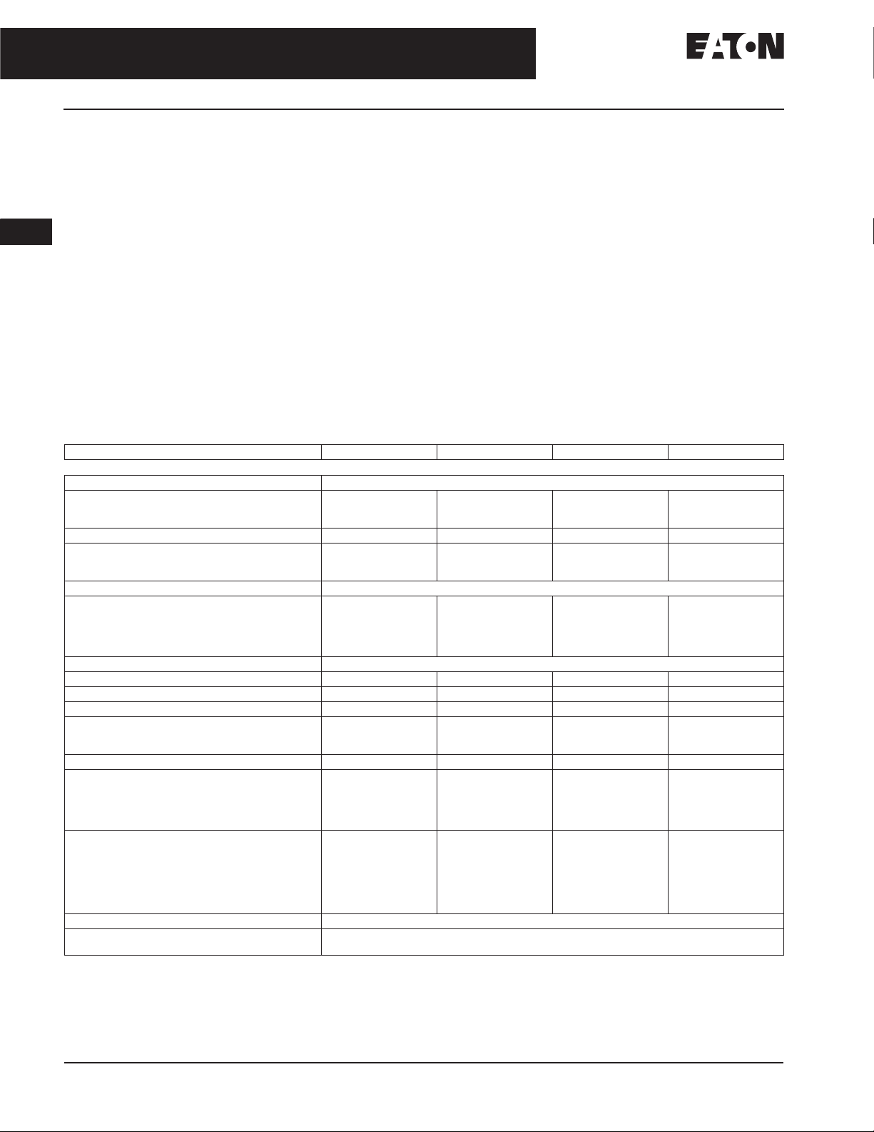
Table 34-107. XT Contactors Technical Data and Specifications — Frame B
Description XTCE007B XTCE009B XTCE012B, XTCF020B XTCE015B
General
Standards IEC/EN 60947, VDE 0660, UL, CSA, CCC, RoHS
Weights in kg [Lb]
AC operated
DC operated
Mechanical Life 10,000,000 10,000,000 10,000,000 10,000,000
Mechanical Operating Frequency (ops/hr)
AC operated
DC operated
Electrical Life See Curves,
Electrical Operating Frequency (ops/hr) —
see Curve,
AC-1; 400V I
AC-3; 400V I
AC-4; 400V I
Climatic Proofing Damp heat, constant, to IEC 60068-2-78; Damp heat, cyclical, to IEC 60068-2-30
Insulation Voltage (U
Impulse Withstand Voltage (U
Operational Voltage (Ue) V AC 690 690 690 690
Safe Isolation to VDE 0106 Part 101 and Part 101/A1
Between coil and contacts (V AC)
Between contacts (V AC)
Making Capacity Up to 690V (Amps)
Breaking Capacity (Amps)
220/230V
380/400V
500V
660/690V
Short-Circuit Protection Rating Maximum Fuse
Type 2 Coordination
Type 1 Coordination
Degree of Protection IP20
Protection against Direct Contact when Actuated
from Front (IEC 536)
Page 34-82
e
e
e
) V AC 690 690 690 690
i
400V; gG/gL 500V
690V; gG/gL 690V
400V; gG/gL 500V
690V; gG/gL 690V
IEC 60947 Standard.
Rated operational current: Making and breaking conditions to DC-13, L/R constant as stated.
) V AC 8000 8000 8000 8000
imp
Frame B XTCE Contactor
0.23 [0.51]
0.28 [0.62]
9000
9000
800
1000
300
400
400
112 112 144 155
70
70
50
40
20
16
35
20
0.23 [0.51]
0.28 [0.62]
9000
9000
800
1000
300
400
400
90
90
70
50
20
16
35
20
0.23 [0.51]
0.28 [0.62]
9000
9000
Page 34-82
800
1000
300
400
400
120
120
100
70
20
20
35
20
Finger- and back-of-hand proof
0.23 [0.51]
0.28 [0.62]
5000
5000
800
1000
300
400
400
124
124
100
70
20
20
63
50
February 2007
For more information visit: www.eaton.com CA08102001E
IEC Contactors & Starters
XT IEC Power Control
February 2007
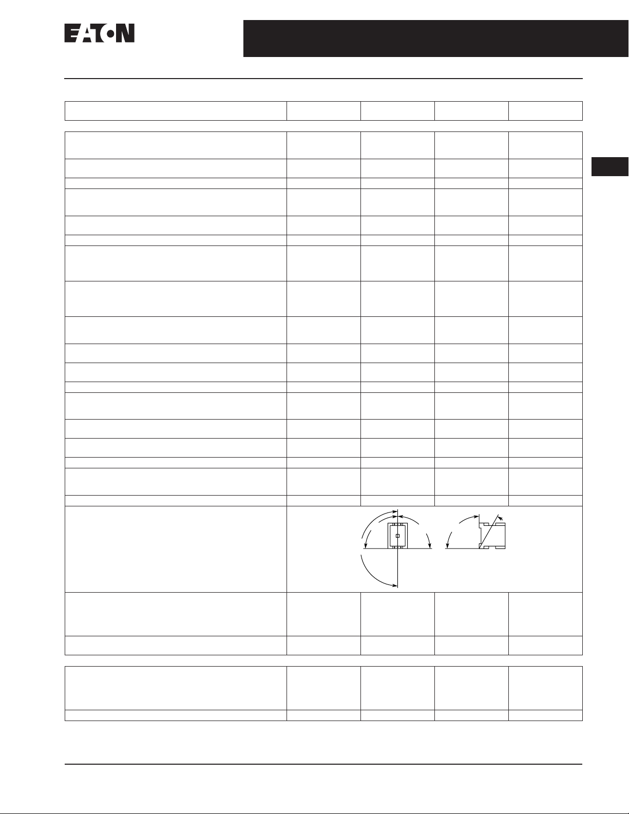
Table 34-107. XT Contactors Technical Data and Specifications — Frame B (Continued)
Description XTCE007B XTCE009B XTCE012B,
General (Continued)
Terminal Capacity Main Cable — Screw Terminals
Solid (mm
Flexible with ferrule (mm
Solid or Stranded (AWG) 18 – 14 18 – 14 18 – 14 18 – 14
Terminal Capacity Control Circuit Cable — Screw Terminals
Solid (mm
Flexible with ferrule (mm
Solid or Stranded (AWG) 18 – 14 18 – 14 18 – 14 18 – 14
Main Cable and Control Circuit Cable Connection Screw/Bolt
Tightening torque
Tools
Main and Control circuit cable — Screw Terminals
Terminal Capacity Main Circuit Cable — Spring Cage Terminals
Solid (mm
Flexible (mm
Flexible with ferrule (mm
Solid or Stranded (AWG) 18 – 14 18 – 14 18 – 14 —
Terminal Capacity Control Circuit Cable — Spring Cage Terminals
Solid (mm
Flexible (mm
Flexible with ferrule (mm
Solid or Stranded (AWG) 18 – 14 18 – 14 18 – 14 —
Tools
Main and Control Circuit Cable — Spring Cage Terminals
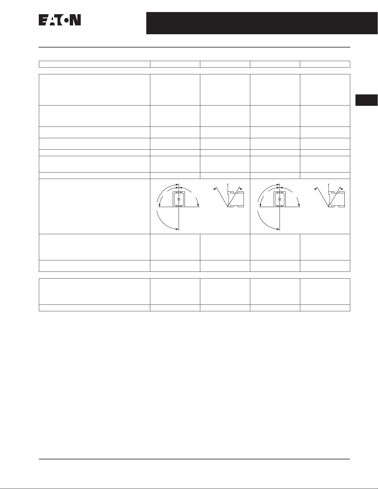
Mounting Position, AC and DC Operated
2
) 1 x (0.75 – 4)
2
) 1 x (0.75 – 2.5)
2
) 1 x (0.75 – 4)
2
) 1 x (0.75 – 2.5)
Nm
Lb-in
Pozidriv screwdriver
Standard screwdriver
2
) 1 x (0.75 – 2.5)
2
) 1 x (0.75 – 2.5)
2
) 1 x (0.75 – 2.5)
2
) 1 x (0.75 – 2.5)
2
) 1 x (0.75 – 2.5)
2
) 1 x (0.75 – 2.5)
Stripping Length (mm) 10 10 10 10
Screwdriver blade width (mm) 3.5 3.5 3.5 3.5
Contactors and Starters
2 x (0.75 – 2.5)
1 x (0.75 – 2.5)
2 x (0.75 – 2.5)
1 x (0.75 – 2.5)
M3.5
1.2
10.6
Size 2
0.8 x 5.5
1 x 6
1 x (0.75 – 2.5)
1 x (0.75 – 2.5)
1 x (0.75 – 2.5)
1 x (0.75 – 2.5)
1 x (0.75 – 2.5)
1 x (0.75 – 2.5)
1 x (0.75 – 4)
2 x (0.75 – 2.5)
1 x (0.75 – 2.5)
1 x (0.75 – 2.5)
1 x (0.75 – 4)
2 x (0.75 – 2.5)
1 x (0.75 – 2.5)
1 x (0.75 – 2.5)
M3.5
1.2
10.6
Size 2
0.8 x 5.5
1 x 6
1 x (0.75 – 2.5)
1 x (0.75 – 2.5)
1 x (0.75 – 2.5)
1 x (0.75 – 2.5)
1 x (0.75 – 2.5)
1 x (0.75 – 2.5)
1 x (0.75 – 2.5)
1 x (0.75 – 2.5)
1 x (0.75 – 2.5)
1 x (0.75 – 2.5)
1 x (0.75 – 2.5)
1 x (0.75 – 2.5)
0°
9
XTCF020B
1 x (0.75 – 4)
2 x (0.75 – 2.5)
1 x (0.75 – 2.5)
1 x (0.75 – 2.5)
1 x (0.75 – 4)
2 x (0.75 – 2.5)
1 x (0.75 – 2.5)
1 x (0.75 – 2.5)
M3.5
1.2
10.6
Size 2
0.8 x 5.5
1 x 6
1 x (0.75 – 2.5)
1 x (0.75 – 2.5)
1 x (0.75 – 2.5)
1 x (0.75 – 2.5)
1 x (0.75 – 2.5)
1 x (0.75 – 2.5)
1 x (0.75 – 2.5)
1 x (0.75 – 2.5)
1 x (0.75 – 2.5)
1 x (0.75 – 2.5)
1 x (0.75 – 2.5)
1 x (0.75 – 2.5)
9
0
°
XTCE015B
1 x (0.75 – 4)
2 x (0.75 – 2.5)
1 x (0.75 – 2.5)
1 x (0.75 – 2.5)
1 x (0.75 – 4)
2 x (0.75 – 2.5)
1 x (0.75 – 2.5)
1 x (0.75 – 2.5)
M3.5
1.2
10.6
Size 2
0.8 x 5.5
1 x 6
—
—
—
—
—
—
—
—
—
—
—
—
30°
°
90
34-61
34
180°
Ambient Temperature
Open
Enclosed
Ambient Storage Temperature -40 to 80°C
-25 to 60°C
[-13 to 140°F]
-25 to 40°C
[-13 to 104°F]
[-40 to 176°F]
-25 to 60°C
[-13 to 140°F]
-25 to 40°C
[-13 to 104°F]
-40 to 80°C
[-40 to 176°F]
-25 to 60°C
[-13 to 140°F]
-25 to 40°C
[-13 to 104°F]
-40 to 80°C
[-40 to 176°F]
Environmental
Mechanical Shock Resistance (IEC/EN 60068-2-27)
Half-sinusoidal shock 10 mS
Main contact — NO Contact
Auxiliary contact — NO Contact
Auxiliary contact — NC Contact
Overvoltage Category/Pollution degree III/3 III/3 III/3 III/3
10g
7g
5g
10g
7g
5g
10g
7g
5g
CA08102001E For more information visit: www.eaton.com
-25 to 60°C
[-13 to 140°F]
-25 to 40°C
[-13 to 104°F]
-40 to 80°C
[-40 to 176°F]
10g
7g
5g
34-62
34
IEC Contactors & Starters
XT IEC Power Control
Contactors and Starters
Frame C – D
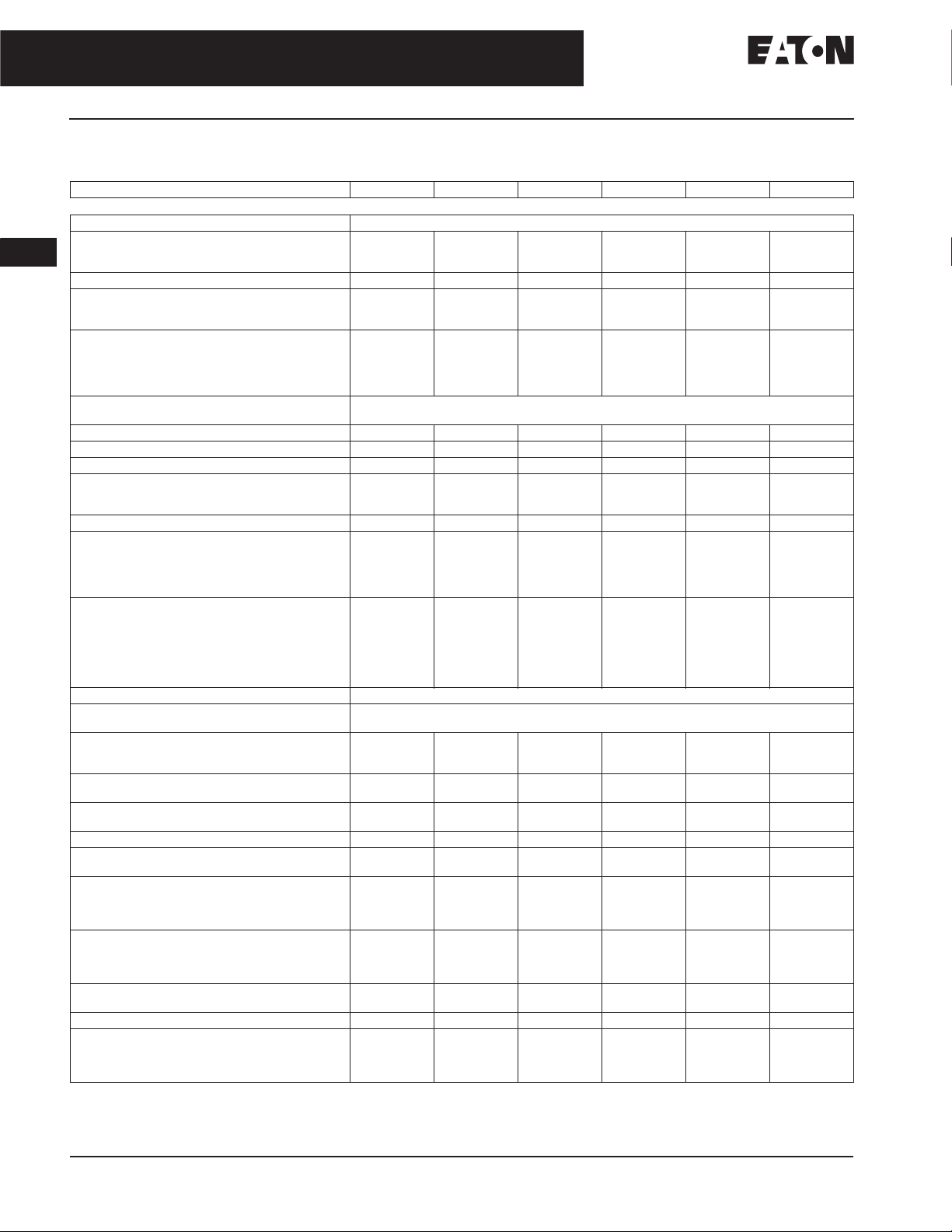
Table 34-108. XT Contactors Technical Data and Specifications — Frame C – D
Description XTCE018C XTCE025C XTCE032C XTCE040D XTCE050D XTCE065D
General
Standards IEC/EN 60947, VDE 0660, UL, CSA, CCC, RoHS
Weights in kg [Lb]
AC operated
DC operated
Mechanical Life 10,000,000 10,000,000 10,000,000 10,000,000 10,000,000 10,000,000
Mechanical Operating Frequency (ops/hr)
AC operated
DC operated
Electrical Mechanical Operating Frequency (ops/hr) —
see Curve,
AC-1; 400V I
AC-3; 400V I
AC-4; 400V I
Climatic Proofing Damp heat, constant, to IEC 60068-2-78;
Insulation Voltage (U
Impulse Withstand Voltage (U
Operating Voltage (Ue) V AC 690 690 690 690 690 690
Safe Isolation to VDE 0106 Part 101 and Part 101/A1
Between coil and contacts (V AC)
Between contacts (V AC)
Making Capacity (Amps) 238 350 384 560 700 910
Breaking Capacity (Amps)
220/230V
380/400V
500V
660/690V
Short-Circuit Protection Rating Maximum Fuse (Amps)
Type 2 Coordination
Type 1 Coordination
Degree of Protection IP00
Protection against Direct Contact when
Actuated from Front (IEC 536)
Terminal Capacity Main Cable — Screw Terminals
Solid (mm
Flexible with ferrule (mm
Stranded (mm
Solid or Stranded (AWG) 18 – 6 18 – 6 18 – 6 12 – 2 12 – 2 12 – 2
Flat Conductor
(Number of Segments x Width x Thickness) (mm)
Main Cable Connection Screw/Bolt
Tightening torque
Terminal Capacity Control Circuit Cable —
Screw Terminals
Solid (mm
Flexible with ferrule (mm
Solid or Stranded (AWG) 18 – 14 18 – 14 18 – 14 18 – 14 18 – 14 18 – 14
Control Circuit Cable Connection Screw/Bolt
Tightening torque
Page 34-82
e
e
e
i
400V; gG/gL 500V
690V; gG/gL 690V
400V; gG/gL 500V
690V; gG/gL 690V
2
) 1 x (0.75 – 16)
2
) 1 x 16 1 x 16 1 x 16 1 x (16 – 50)
Nm
Lb-in
2
) 1 x (0.75 – 4)
Nm
Lb-in
IEC 60947 Standard.
) V AC 690 690 690 690 690 690
) V AC 8000 8000 8000 8000 8000 8000
imp
2
) 1 x (0.75 – 16)
2
) 1 x (0.75 – 2.5)
0.42 [0.93]
0.48 [1.06]
5000
5000
800
800
300
440
238
170
170
170
120
25
25
63
50
2 x (0.75 – 10)
2 x (0.75 – 10)
———2 x (6 x 9 x 0.8)2 x (6 x 9 x 0.8)2 x (6 x 9 x 0.8)
M5
3
26.6
2 x (0.75 – 4)
2 x (0.75 – 2.5)
M3.5
1.2
10.6
0.42 [0.93]
0.48 [1.06]
5000
5000
800
800
300
440
440
250
250
250
150
35
35
100
50
1 x (0.75 – 16)
2 x (0.75 – 10)
1 x (0.75 – 16)
2 x (0.75 – 10)
M5
3
26.6
1 x (0.75 – 4)
2 x (0.75 – 4)
1 x (0.75 – 2.5)
2 x (0.75 – 2.5)
M3.5
1.2
10.6
0.42 [0.93]
0.48 [1.06]
5000
5000
800
800
300
Damp heat, cyclic, to IEC 60 068-2-30
440
440
320
320
320
180
63
35
125
63
Finger- and back-of-hand proof
1 x (0.75 – 16)
2 x (0.75 – 10)
1 x (0.75 – 16)
2 x (0.75 – 10)
M5
3
26.6
1 x (0.75 – 4)
2 x (0.75 – 4)
1 x (0.75 – 2.5)
2 x (0.75 – 2.5)
M3.5
1.2
10.6
0.9 [2.0]
1.1 [2.4]
5000
5000
800
800
300
440
440
400
400
400
250
63
50
125
80
1 x (0.75 – 16)
2 x (0.75 – 10)
1 x (2.5 – 35)
2 x (2.5 – 25)
2 x (16 – 35)
M6
3.3
29.2
1 x (0.75 – 4)
2 x (0.75 – 4)
1 x (0.75 – 2.5)
2 x (0.75 – 2.5)
M3.5
1.2
10.6
0.9 [2.0]
1.1 [2.4]
5000
5000
800
800
300
440
440
500
500
500
320
80
63
160
80
1 x (0.75 – 16)
2 x (0.75 – 10)
1 x (2.5 – 35)
2 x (2.5 – 25)
1 x (16 – 50)
2 x (16 – 35)
M6
3.3
29.2
1 x (0.75 – 4)
2 x (0.75 – 4)
1 x (0.75 – 2.5)
2 x (0.75 – 2.5)
M3.5
1.2
10.6
February 2007
0.9 [2.0]
1.1 [2.4]
5000
5000
800
800
300
440
440
650
650
650
370
125
80
250
100
1 x (0.75 – 16)
2 x (0.75 – 10)
1 x (2.5 – 35)
2 x (2.5 – 25)
1 x (16 – 50)
2 x (16 – 35)
M6
3.3
29.2
1 x (0.75 – 4)
2 x (0.75 – 4)
1 x (0.75 – 2.5)
2 x (0.75 – 2.5)
M3.5
1.2
10.6
For more information visit: www.eaton.com CA08102001E
IEC Contactors & Starters
XT IEC Power Control
February 2007
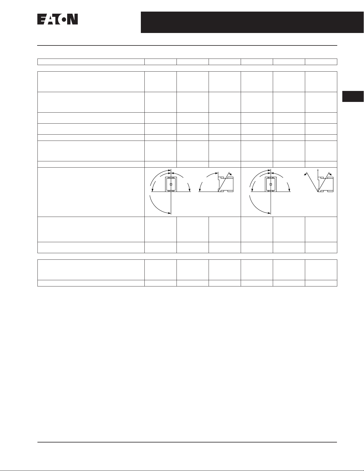
Table 34-108. XT Contactors Technical Data and Specifications — Frame C – D (Continued)
Description XTCE018C XTCE025C XTCE032C XTCE040D XTCE050D XTCE065D
General (Continued)
Tools
Main and Control Circuit Cable — Screw Terminals
Pozidriv screwdriver
Standard screwdriver
Terminal Capacity Control Circuit Cable —
Spring Cage Terminals
Solid (mm
Flexible (mm
Flexible with ferrule (mm
Solid or Stranded (AWG) 18 – 14 18 – 14 18 – 14 18 – 14 18 – 14 18 – 14
Tools
Main and Control Circuit Cable —
Spring Cage Terminals
Screwdriver blade width (mm) 3.5 3.5 3.5 3.5 3.5 3.5
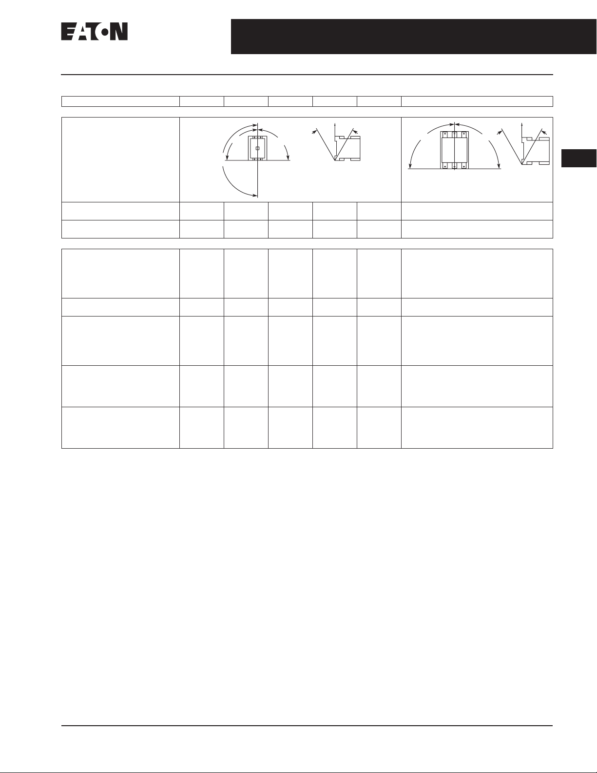
Mounting Position, AC and DC operated
2
) 1 x (0.75 – 2.5)
2
) 1 x (0.75 – 2.5)
2
) 1 x (0.75 – 2.5)
Stripping Length (mm) 10 10 10 10 10 10
Contactors and Starters
Size 2
0.8 x 5.5
1 x 6
2 x (0.75 – 2.5)
2 x (0.75 – 2.5)
2 x (0.75 – 2.5)
0°
9
Size 2
0.8 x 5.5
1 x 6
1 x (0.75 – 2.5)
2 x (0.75 – 2.5)
1 x (0.75 – 2.5)
2 x (0.75 – 2.5)
1 x (0.75 – 2.5)
2 x (0.75 – 2.5)
9
0
°
Size 2
0.8 x 5.5
1 x 6
1 x (0.75 – 2.5)
2 x (0.75 – 2.5)
1 x (0.75 – 2.5)
2 x (0.75 – 2.5)
1 x (0.75 – 2.5)
2 x (0.75 – 2.5)
°
90
30°
Size 2
0.8 x 5.5
1 x 6
1 x (0.75 – 2.5)
2 x (0.75 – 2.5)
1 x (0.75 – 2.5)
2 x (0.75 – 2.5)
1 x (0.75 – 2.5)
2 x (0.75 – 2.5)
0°
9
Size 2
0.8 x 5.5
1 x 6
1 x (0.75 – 2.5)
2 x (0.75 – 2.5)
1 x (0.75 – 2.5)
2 x (0.75 – 2.5)
1 x (0.75 – 2.5)
2 x (0.75 – 2.5)
9
0
°
Size 2
0.8 x 5.5
1 x 6
1 x (0.75 – 2.5)
2 x (0.75 – 2.5)
1 x (0.75 – 2.5)
2 x (0.75 – 2.5)
1 x (0.75 – 2.5)
2 x (0.75 – 2.5)
30° 30°
34-63
34
180°
Ambient Temperature
Open
Enclosed
Ambient Storage Temperature -40 to 80°C
-25 to 60°C
[-13 to 140°F]
-25 to 40°C
[-13 to 104°F]
[-40 to 176°F]
-25 to 60°C
[-13 to 140°F]
-25 to 40°C
[-13 to 104°F]
-40 to 80°C
[-40 to 176°F]
-25 to 60°C
[-13 to 140°F]
-25 to 40°C
[-13 to 104°F]
-40 to 80°C
[-40 to 176°F]
180°
-25 to 60°C
[-13 to 140°F]
-25 to 40°C
[-13 to 104°F]
-40 to 80°C
[-40 to 176°F]
-25 to 60°C
[-13 to 140°F]
-25 to 40°C
[-13 to 104°F]
-40 to 80°C
[-40 to 176°F]
Environmental
Mechanical Shock Resistance (IEC/EN 60068-2-27)
Main contact — NO Contact
Auxiliary contact — NO Contact
Auxiliary contact — NC Contact
Overvoltage Category / Pollution Degree III/3 III/3 III/3 III/3 III/3 III/3
10
7
5
10
7
5
10
7
5
10
7
5
10
7
5
-25 to 60°C
[-13 to 140°F]
-25 to 40°C
[-13 to 104°F]
-40 to 80°C
[-40 to 176°F]
10
7
5
CA08102001E For more information visit: www.eaton.com

34-64
34
IEC Contactors & Starters
XT IEC Power Control
Contactors and Starters
Frame F – G
Table 34-109. XT Contactors Technical Data and Specifications — Frame F – G
Description XTCE080F XTCE095F XTCE115G XTCE150G
General
Standards IEC/EN 60947, VDE 0660, UL, CSA, CCC, RoHS
Weights in kg [Lb]
AC operated
DC operated
Mechanical Life 10,000,000 10,000,000 10,000,000 10,000,000
Mechanical Operating Frequency (ops/hr)
AC operated
DC operated
Electrical Mechanical Operating Frequency (ops/hr) —
see Curve,
AC-1; 400V I
AC-3; 400V I
AC-4; 400V I
Climatic Proofing Damp heat, constant, to IEC 60068-2-78; Damp heat, cyclic, to IEC 60 068-2-30
Insulation Voltage (U
Impulse Withstand Voltage (U
Operational Voltage (Ue) V AC 1000 1000 1000 1000
Safe Isolation to VDE 0106 Part 101 and Part 101/A1
Between coil and contacts (V AC)
Between contacts (V AC)
Making Capacity (Amps) 1120 1330 1610 2100
Breaking Capacity (Amps)
220/230V
380/400V
500V
660/690V
1000V
Short-Circuit Protection Rating Maximum Fuse
Type 2 Coordination
Type 1 Coordination
Degree of Protection IP00
Protection Against Direct Contact when
Actuated from Front (IEC 536)
Terminal Capacity Main Cable — Screw Terminals
Solid (mm
Flexible with ferrule (mm2) 1 x (10 – 95)
Stranded (mm
Flat Conductor
(Number of Segments x Width x Thickness) (mm)
Solid or Stranded (AWG) 8 – 250 MCM 8 – 250 MCM 8 – 250 MCM 8 – 250 MCM
Main Cable Connection Screw/Bolt
Tightening torque
Terminal Capacity Control Circuit Cable —
Screw Terminals
Solid (mm
Flexible with ferrule (mm
Solid or Stranded (AWG) 18 – 14 18 – 14 18 – 14 18 – 14
Control Circuit Cable Connection Screw/Bolt
Tightening torque
Page 34-82
e
e
e
i
400V; gG/gL 500V
690V; gG/gL 690V
400V; gG/gL 500V
690V; gG/gL 690V
2
) ————
2
) 1 x (16 – 120)
Nm
Lb-in
2
) 1 x (0.75 – 4)
Nm
Lb-in
Contact Eaton.
IEC 60947 Standard.
) V AC 1000 1000 1000 1000
) V AC 8000 8000 8000 8000
imp
2
) 1 x (0.75 – 2.5)
2 [4.41]
2.1 [4.63]
3600
3600
800
800
300
690
690
800
800
800
650
—
160
160
250
200
2 x (10 – 70)
2 x (16 – 95)
2 x (6 x 16 x 0.8) 2 x (6 x 16 x 0.8) 2 x (6 x 16 x 0.8) 2 x (6 x 16 x 0.8)
M10
14
123.9
1 x (0.75 – 4)
2 x (0.75 – 2.5)
M3.5
1.2
10.6
2 [4.41]
2.1 [4.63]
3600
3600
800
800
300
690
690
950
950
950
800
—
160
160
250
200
Finger- and back-of-hand proof
1 x (10 – 95)
2 x (10 – 70)
1 x (16 – 120)
2 x (16 – 95)
M10
14
123.9
1 x (0.75 – 4)
1 x (0.75 – 4)
1 x (0.75 – 2.5)
2 x (0.75 – 2.5)
M3.5
1.2
10.6
2 [4.41]
2.1 [4.63]
3600
3600
800
800
300
690
690
1150
1150
1150
1100
—
250
250
1 x (10 – 95)
2 x (10 – 70)
1 x (16 – 120)
2 x (16 – 95)
M10
14
123.9
1 x (0.75 – 4)
1 x (0.75 – 4)
1 x (0.75 – 2.5)
2 x (0.75 – 2.5)
M3.5
1.2
10.6
2 [4.41]
2.1 [4.63]
3600
3600
800
800
300
690
690
1500
1500
1500
1200
—
250
250
1 x (10 – 95)
2 x (10 – 70)
1 x (16 – 120)
2 x (16 – 95)
M10
14
123.9
1 x (0.75 – 4)
1 x (0.75 – 4)
1 x (0.75 – 2.5)
2 x (0.75 – 2.5)
M3.5
1.2
10.6
February 2007
For more information visit: www.eaton.com CA08102001E
IEC Contactors & Starters
XT IEC Power Control
February 2007
Table 34-109. XT Contactors Technical Data and Specifications — Frame F – G (Continued)
Description XTCE080F XTCE095F XTCE115G XTCE150G
General (Continued)
Tools
Main Circuit Cable — Screw Terminals
Hexagon Socket-Head Spanner (mm)
Control Circuit Cable — Screw Terminals
Pozidriv screwdriver
Standard screwdriver
Terminal Capacity Control Circuit Cable —
Spring Cage Terminals
Solid (mm
Flexible (mm
Flexible with ferrule (mm
Solid or Stranded (AWG) 18 – 14 18 – 14 18 – 14 18 – 14
Tools
Control Circuit Cable — Spring Cage Terminals
Screwdriver blade width (mm) 3.5 3.5 3.5 3.5
Mounting Position, AC and DC operated
2
) 1 x (0.75 – 2.5)
2
) 1 x (0.75 – 2.5)
2
) 1 x (0.75 – 2.5)
Stripping Length (mm) 10 10 10 10
Contactors and Starters
5
Size 2
0.8 x 5.5
1 x 6
2 x (0.75 – 2.5)
2 x (0.75 – 2.5)
2 x (0.75 – 2.5)
0°
9
9
0
5
Size 2
0.8 x 5.5
1 x 6
1 x (0.75 – 2.5)
2 x (0.75 – 2.5)
1 x (0.75 – 2.5)
2 x (0.75 – 2.5)
1 x (0.75 – 2.5)
2 x (0.75 – 2.5)
°
30° 30°
5
Size 2
0.8 x 5.5
1 x 6
1 x (0.75 – 2.5)
2 x (0.75 – 2.5)
1 x (0.75 – 2.5)
2 x (0.75 – 2.5)
1 x (0.75 – 2.5)
2 x (0.75 – 2.5)
0°
9
5
Size 2
0.8 x 5.5
1 x 6
1 x (0.75 – 2.5)
2 x (0.75 – 2.5)
1 x (0.75 – 2.5)
2 x (0.75 – 2.5)
1 x (0.75 – 2.5)
2 x (0.75 – 2.5)
9
0
°
34-65
34
30° 30°
180°
Ambient Temperature
Open
Enclosed
Ambient Storage Temperature -40 to 80°C
-25 to 60°C
[-13 to 140°F]
-25 to 40°C
[-13 to 104°F)
[-40 to 176°F]
-25 to 60°C
[-13 to 140°F]
-25 to 40°C
[-13 to 104°F)
-40 to 80°C
[-40 to 176°F]
180°
-25 to 60°C
[-13 to 140°F]
-25 to 40°C
[-13 to 104°F)
-40 to 80°C
[-40 to 176°F]
Environmental
Mechanical Shock Resistance (IEC/EN 60068-2-27)
Half-sinusoidal shock 10 mS
Main contact — NO Contact
Auxiliary contact — NO Contact
Auxiliary contact — NC Contact
Overvoltage Category/Pollution Degree III/3 III/3 III/3 III/3
10g
7g
5g
10g
7g
5g
10g
7g
5g
-25 to 60°C
[-13 to 140°F]
-25 to 40°C
[-13 to 104°F)
-40 to 80°C
[-40 to 176°F]
10g
7g
5g
CA08102001E For more information visit: www.eaton.com

34-66
34
IEC Contactors & Starters
XT IEC Power Control
Contactors and Starters
Frame L – M
Table 34-110. XT Contactors Technical Data and Specifications — Frame L – M
Description XTCE185L XTCE225L XTCE250L XTCE300M XTCE400M XTCE500M
General
Standards IEC/EN 60947, VDE 0660, UL, CSA
Weights in kg [Lb] 6.5 [14.3] 6.5 [14.3] 6.5 [14.3] 8 [18] 8 [18] 8 [18]
Mechanical Life 10,000,000 10,000,000 10,000,000 7000000 7000000 7000000
Mechanical Operating Frequency (ops/hr)
AC operated
DC operated
Mechanical Operating Frequency (ops/hr) See Figure 34-43 on
Climatic Proofing Damp heat, constant, to IEC 60068-2-78; Damp heat, cyclic, to IEC 60 068-2-30
Insulation Voltage (Ui) V AC 1000 1000 1000 1000 1000 1000
Impulse Withstand Voltage (U
Operating Voltage (Ue) V AC 1000 1000 1000 1000 1000 1000
Safe Isolation to VDE 0106 Part 101 and Part 101/A1
Between coil and contacts (V AC)
Between contacts (V AC)
Making Capacity (Amps) 3000 3000 3000 5500 5500 5500
Breaking Capacity (Amps)
220/230V
380/400V
500V
660/690V
1000V
Short-Circuit Protection Rating Maximum Fuse
Type 2 Coordination
400V; gG/gL 500V
690V; gG/gL 690V
1000V; gG/gL 1000V
Type 1 Coordination
400V; gG/gL 500V
690V; gG/gL 690V
1000V; gG/gL 1000V
Degree of Protection IP00
Protection Against Direct Contact when
Actuated from Front (Iec 536)
Main Cable Cross-Section
Flexible with cable lug (mm
Stranded with cable lug (mm
Solid or Stranded (AWG)
Flat Conductor (mm)
Busbar — Width in mm
Main Cable Connection Screw/Bolt
Tightening torque
Nm
Lb-in
Control Circuit Cable Cross-Sections
Solid (mm
Flexible with ferrule (mm
Solid or Stranded (AWG) 2 x (18 – 12) 2 x (18 – 12) 2 x (18 – 12) 2 x (18 – 12) 2 x (18 – 12) 2 x (18 – 12)
Control Circuit Cable Connection Screw/Bolt
Tightening torque
Tools
Main cable wrench
Control circuit cable pozidriv screwdriver
Screw tightening with flat cable terminal or cable terminal blocks. See terminal capacity for cable terminal blocks.
IEC 60947 Standard.
2
Nm
Lb-in
) 1 x (0.75 – 2.5)
) V AC 8000 8000 8000 8000 8000 8000
imp
2
)
2
)
2
) 1 x (0.75 – 2.5)
3000
3000
500
500
2500
2500
2500
2500
760
315
315
160
400
400
200
35 – 95
50 – 120
20
M10
24
213
2 x (0.75 – 2.5)
2 x (0.75 – 2.5)
M3.5
1.2
10.6
16 mm
Size 2
3000
3000
500
500
2500
2500
2500
2500
760
315
315
160
400
400
200
Finger- and back-of-hand proof with terminal shroud or terminal block.
50 – 240
70 – 240
1/0 – 250 MCM
20
M10
24
213
1 x (0.75 – 2.5)
2 x (0.75 – 2.5)
1 x (0.75 – 2.5)
2 x (0.75 – 2.5)
M3.5
1.2
10.6
16 mm
Size 2
3000
3000
500
500
2500
2500
2500
2500
760
315
315
160
400
400
200
50 – 240
70 – 240
1/0 – 250 MCM
25
M10
24
213
1 x (0.75 – 2.5)
2 x (0.75 – 2.5)
1 x (0.75 – 2.5)
2 x (0.75 – 2.5)
M3.5
1.2
10.6
16 mm
Size 2
2000
2000
Page 34-83
500
500
5000
5000
5000
5000
950
500
500
200
630
630
250
50 – 240
70 – 240
1/0 – 250 MCM
25
M10
24
213
1 x (0.75 – 2.5)
2 x (0.75 – 2.5)
1 x (0.75 – 2.5)
2 x (0.75 – 2.5)
M3.5
1.2
10.6
16 mm
Size 2
2000
2000
.
500
500
5000
5000
5000
5000
950
500
500
200
630
630
250
50 – 240
70 – 240
1/0 – 250 MCM
25
M10
24
213
1 x (0.75 – 2.5)
2 x (0.75 – 2.5)
1 x (0.75 – 2.5)
2 x (0.75 – 2.5)
M3.5
1.2
10.6
16 mm
Size 2
February 2007
2000
2000
500
500
5000
5000
5000
5000
950
500
500
200
630
630
250
50 – 240
70 – 240
1/0 – 250 MCM
30
M10
24
213
1 x (0.75 – 2.5)
2 x (0.75 – 2.5)
1 x (0.75 – 2.5)
2 x (0.75 – 2.5)
M3.5
1.2
10.6
16 mm
Size 2
For more information visit: www.eaton.com CA08102001E
IEC Contactors & Starters
XT IEC Power Control
February 2007
Table 34-110. XT Contactors Technical Data and Specifications — Frame L – M (Continued)
Description XTCE185L XTCE225L XTCE250L XTCE300M XTCE400M XTCE500M
General (Continued)
Mounting Position,
AC and DC Operated
Contactors and Starters
0°
9
9
0
°
30° 30°
90° 90°
34-67
30°30°
180°
Ambient Temperature -25 to 60°C
[-13 to 140°F]
Ambient Storage Temperature -40 to 80°C
[-40 to 176°F]
-25 to 60°C
[-13 to 140°F]
-40 to 80°C
[-40 to 176°F]
-25 to 60°C
[-13 to 140°F]
-40 to 80°C
[-40 to 176°F]
-25 to 60°C
[-13 to 140°F]
-40 to 80°C
[-40 to 176°F]
-25 to 60°C
[-13 to 140°F]
-40 to 80°C
[-40 to 176°F]
-25 to 60°C
[-13 to 140°F]
-40 to 80°C
[-40 to 176°F]
Environmental
Mechanical Shock
Resistance (IEC/EN 60068-2-27)
Half-sinusoidal shock 10 mS
Main contact — NO Contact
Auxiliary contact — NO Contact
Auxiliary contact — NC Contact
Overvoltage Category/
Pollution Degree
Switching Capacity, kVar
Individual Compensation
230V
400/420/440V
525V
690V
Group Compensation, with Choke
230V
400/420/440V
525V
690V
Group Compensation, without Choke
230V
400/420/440V
525V
690V
When using contactors for group compensation, a minimum inductance of approx. 6 uh per capacitor must be available to limit the high inrush current
peaks. This corresponds to an air-cored coil with 5 windings and a coil diameter of approximately 140 mm. The conductor cross-section must be
selected according to the rated current per phase.
10g
10g
8g
III/3 III/3 III/3 III/3 III/3 III/3
87
150
190
150
80
150
200
260
66
115
145
115
10g
10g
8g
—
—
—
—
100
175
230
300
—
—
—
—
10g
10g
8g
—
—
—
—
110
190
260
340
—
—
—
—
10g
10g
8g
115
200
265
200
130
225
290
390
85
150
195
150
10g
10g
8g
—
—
—
—
160
280
370
480
—
—
—
—
10g
10g
8g
—
—
—
—
160
280
370
480
—
—
—
—
34
CA08102001E For more information visit: www.eaton.com

34-68
34
IEC Contactors & Starters
XT IEC Power Control
Contactors and Starters
Frame N – R
Table 34-111. XT Contactors Technical Data and Specifications — Frame N – R
Description XTCE580N XTCE650N XTCE750N,
XTCE820N,
General
Standards IEC/EN 60947, VDE 0660, UL, CSA
Weights in kg [Lb] 15 [33] 15 [33] 15 [33] 15 [33] 15, 32 [33, 70]
Mechanical Life 5,000,000 5,000,000 5,000,000 5,000,000 5,000,000
Mechanical Operating Frequency (ops/hr)
AC operated
DC operated
Maximum Operating frequency (ops/hr) See Figure 34-43 on
Climatic Proofing Damp heat, constant, to IEC 60068-2-78; Damp heat, cyclic, to IEC 60 068-2-30
Insulation Voltage (U
Impulse Withstand Voltage (U
Operating Voltage (Ue) V AC 1000 1000 1000 1000 1000
Safe Isolation to VDE 0106 Part 101 and Part 101/A1
Between coil and contacts (V AC)
Between contacts (V AC)
Making Capacity (Amps) 7800 7800 9840 9840 9840
Breaking Capacity (Amps)
220/230V
380/400V
500V
660/690V
1000V
Short-Circuit Protection Rating Maximum Fuse
Type 2 Coordination
400V; gG/gL 500V
690V; gG/gL 690V
1000V; gG/gL 1000V
Type 1 Coordination
400V; gG/gL 500V
690V; gG/gL 690V
1000V; gG/gL 1000V
Degree of Protection IP00
Protection Against Direct Contact when
Actuated from Front (Iec 536)
Main Cable Cross-Section
Flexible with cable lug (mm
Stranded with cable lug (mm
Solid or Stranded (AWG)
Flat Conductor (mm)
Busbar — Width in mm
Main Cable Connection Screw/Bolt
Tightening torque
Nm
Lb-in
Control Circuit Cable Cross-Sections
Solid (mm
Flexible with ferrule (mm
Solid or Stranded (AWG)
Control Circuit Cable Connection Screw/Bolt
Tightening torque
Nm
Lb-in
Screw tightening with flat cable terminal or cable terminal blocks. See terminal capacity for cable terminal blocks.
IEC 60947 Standard.
) V AC 1000 1000 1000 1000 1000
i
2
)
) V AC 8000 8000 8000 8000 8000
imp
2
)
2
)
2
)
1000
1000
500
500
6500
6500
6500
6500
4350
630
630
500
1000
1000
630
50-240
70-240
2/0 – 500 MCM
50
M10
24
213
1 x (0.75 – 2.5)
2 x (0.75 – 2.5)
1 x (0.75 – 2.5)
2 x (0.75 – 2.5)
2 x (18 – 12)
M3.5
1.2
10.6
1000
1000
500
500
6500
6500
6500
6500
4350
630
630
500
1000
1000
630
Finger- and back-of-hand proof with terminal shroud or terminal block.
50-240
70-240
2/0 – 500 MCM
50
M10
24
213
1 x (0.75 – 2.5)
2 x (0.75 – 2.5)
1 x (0.75 – 2.5)
2 x (0.75 – 2.5)
2 x (18 – 12)
M3.5
1.2
10.6
1000
1000
500
500
8200
8200
8200
8200
5800
630
630
630
1200
1200
800
50-240
70-240
2/0 – 500 MCM
50
M12
35
311
1 x (0.75 – 2.5)
2 x (0.75 – 2.5)
1 x (0.75 – 2.5)
2 x (0.75 – 2.5)
2 x (18 – 12)
M3.5
1.2
10.6
XTCEC10N XTCEC14P,
1000
1000
Page 34-83
.
500
500
8200
8200
8200
8200
5800
630
630
630
1200
1200
800
50-240
70-240
2/0 – 500 MCM
50
M12
35
311
1 x (0.75 – 2.5)
2 x (0.75 – 2.5)
1 x (0.75 – 2.5)
2 x (0.75 – 2.5)
2 x (18 – 12)
M3.5
1.2
10.6
February 2007
XTCEC20R
1000
1000
500
500
8200
8200
8200
8200
5800
—
—
—
—
—
—
50-240
70-240
2/0 – 500 MCM
50
M12
35
311
1 x (0.75 – 2.5)
2 x (0.75 – 2.5)
1 x (0.75 – 2.5)
2 x (0.75 – 2.5)
2 x (18 – 12)
M3.5
1.2
10.6
For more information visit: www.eaton.com CA08102001E

IEC Contactors & Starters
XT IEC Power Control
February 2007
Table 34-111. XT Contactors Technical Data and Specifications — Frame N – R (Continued)
Description XTCE580N XTCE650N XTCE750N,
General (Continued)
Tools
Main cable wrench
Control circuit cable pozidriv screwdriver
Mounting Position, AC and DC Operated
Contactors and Starters
16 mm
Size 2
180°
0°
9
16 mm
Size 2
XTCE820N,
18 mm
Size 2
9
0
°
30° 30°
XTCEC10N XTCEC14N,
18 mm
Size 2
90° 90°
XTCEC20N
18 mm
Size 2
34-69
30°30°
34
Ambient Temperature -25 to 60°C
[-13 to 140°F]
Ambient Storage Temperature -40 to 80°C
[-40 to 176°F]
-25 to 60°C
[-13 to 140°F]
-40 to 80°C
[-40 to 176°F]
-25 to 60°C
[-13 to 140°F]
-40 to 80°C
[-40 to 176°F]
-25 to 60°C
[-13 to 140°F]
-40 to 80°C
[-40 to 176°F]
-25 to 60°C
[-13 to 140°F]
-40 to 80°C
[-40 to 176°F]
Environmental
Mechanical Shock Resistance (IEC/EN 60068-2-27)
Half-sinusoidal shock 10 mS (g)
Main contact — NO Contact
Auxiliary contact — NO Contact
Auxiliary contact — NC Contact
Overvoltage Category/Pollution Degree III/3 III/3 III/3 III/3 III/3
Switching Capacity, kVar
Individual Compensation
230V
400/420/440V
525V
690V
When using contactors for group compensation, a minimum inductance of approx. 6 uh per capacitor must be available to limit the high inrush current
peaks. This corresponds to an air-cored coil with 5 windings and a coil diameter of approximately 140 mm. The conductor cross-section must be
selected according to the rated current per phase.
10
10
8
175
300
400
300
10
10
8
—
—
—
—
10
10
8
—
—
—
—
10
10
8
—
—
—
—
10
10
8
—
—
—
—
Instructional Leaflets
Table 34-112. Instructional Leaflets
Publication Number Description
Pub51210 7 – 15A, B Frame XTCE, XTCEC and XTCF Contactors and Accessories (Inside of Packaging)
Pub51211 18 – 32A, C Frame XTCE and XTCEC Contactors and Accessories (Inside of Packaging)
Pub51221 XTOB, D Frame Overload Relays (Inside of Packaging)
Pub51222 XTOB, B – C Frame Overload Relays (Inside of Packaging)
Pub51237 7 – 12A, B Frame XTCE Contactors and Auxiliary Contacts
Pub51232 18 – 32A, C Frame XTCE Contactors and Auxiliary Contacts
Pub51216 40 – 65A, D Frame XTCE Contactors and Auxiliary Contacts
Pub51203 185 – 500A, L – M Frame XTCE Contactors and Auxiliary Contacts
Pub51215 S-Series 185 – 500A, L – M Frame XTCE Contactors and Auxiliary Contacts
Pub51204 580 – 1000A, N Frame XTCE Contactors and Auxiliary Contacts
Pub51209 1400 – 2000A, P – R Frame XTCE Contactors and Auxiliary Contacts
Pub51213 7 – 150A, B – G Frame XTAE Non-reversing and XTAR Reversing Starters
Pub51217 XTCEXFA and XTCEXSA Front and Side Mount Auxiliary Contacts from 40 – 150A, D – G Frame XTCE Contactors
Pub51212 XTCEXML Mechanical Interlock for 7 – 150A, B – G Frame XTCE Contactors
Pub51214 XTCEXRL Reversing Link Kits for 18 – 32A, C Frame XTCE Contactors
Pub51218 XTCEXTL Lug Kits for 500 – 820A, M – N Frame XTCE Contactors
Pub51219 XTCEXRLB and XTCEXSDLB Reversing and Star-Delta (Wye-Delta) Link Kits for 7 – 12A, B Frame XTCE Contactors
Pub51205 Accessories for 185 – 500A, L – M Frame XTCE Contactors
Pub51207 Replacement DC Coils
Pub51213 Renewal Parts — Coils for 18 – 32A, C Frame XTCE Contactors
Pub51186 Renewal Parts — Coils for 40 – 65A, D Frame XTCE Contactors
CA08102001E For more information visit: www.eaton.com

34-70
34
IEC Contactors & Starters
XT IEC Power Control
Contactors and Starters
Coil Data
Frame B – D
Table 34-113. Coil Data — Frame B – D
XTCE007B XTCE009B XTCE012B
XTCF020B
Voltage Tolerance
Pick-Up (x Uc)
AC operated
DC operated
Drop-Out (x U
AC operated
DC operated
)
c
0.8 – 1.1
0.8 – 1.1
0.3 – 0.6
0.15 – 0.6
Power Consumption of the coil at cold state and 1.0 x U
AC operated
Single-voltage coil 50 Hz
Pick-Up VA
Pick-Up W
Sealing VA
Sealing W
Single-voltage coil 60 Hz
Pick-Up VA
Pick-Up W
Sealing VA
Sealing W
50/60 Hz
Pick-Up VA
Pick-Up W
Sealing VA
Sealing W
DC operated
Pick-Up W
Sealing W
Duty Factor (%DF) 100 100 100 100 100 100 100 100 100 100
24
19
3.4
1.2
30
23
4.4
1.4
27
25
22
21
4.2
3.3
1.4
1.2
3
3
0.8 – 1.1
0.8 – 1.1
0.3 – 0.6
0.15 – 0.6
24
19
3.4
1.2
30
23
4.4
1.4
27
25
22
21
4.2
3.3
1.4
1.2
3
3
c
0.8 – 1.1
0.8 – 1.1
0.3 – 0.6
0.15 – 0.6
24
19
3.4
1.2
30
23
4.4
1.4
27
25
22
21
4.2
3.3
1.4
1.2
4.5
4.5
Switching Time at 100% Uc(approximate values)
Main Contact
AC operated
Closing delay (mS)
Opening delay (mS)
DC operated
Closing delay (mS)
Opening delay (mS)
Arcing time (mS) 10 10 10 10 10 10 10 10 10 10
<21
<18
<31
<12
<21
<18
<31
<12
<21
<18
<31
<12
Electromagnetic Compatibility (EMC)
Emitted interference To EN-60947-1
Noise Immunity To EN-60947-1
0.7 – 1.3 without additional auxiliary contact modules and ambient temperature +40°C [104°F].
Coil Suffix TD: U
Coil Suffix WD: U
Coil Suffix AD: U
Coil Suffix BD: U
Example:
= 0.7 x U
U
c
Uc = 0.7 x 24V — 1.2 x 27V DC
— 1.2 x U
min
min
min
min
min
24V DC/U
48V DC/U
110V DC/U
200V DC/U
max
max
max
max
max
27V DC.
60V DC.
130V DC.
240V DC.
XTCE015B XTCE018C XTCE025C XTCE032C XTCE040D XTCE050D XTCE065D
0.8 – 1.1
0.8 – 1.1
0.3 – 0.6
0.15 – 0.6
24
19
3.4
1.2
30
23
4.4
1.4
27
25
22
21
4.2
3.3
1.4
1.2
4.5
4.5
<21
<18
<31
<12
0.8 – 1.1
0.7 – 1.2
0.3 – 0.6
0.15 – 0.6
52
40
7.1
2.1
67
50
8.7
2.6
62
58
48
43
9.1
6.5
2.5
2
12 at 24V
0.5 at 24V
<22
<14
<47
<30
0.8 – 1.1
0.7 – 1.2
0.3 – 0.6
0.15 – 0.6
52
40
7.1
2.1
67
50
8.7
2.6
62
58
48
43
9.1
6.5
2.5
2
12 at 24V
0.5 at 24V
<22
<14
<47
<30
0.8 – 1.1
0.7 – 1.2
0.3 – 0.6
0.15 – 0.6
52
40
7.1
2.1
67
50
8.7
2.6
62
58
48
43
9.1
6.5
2.5
2
12 at 24V
0.5 at 24V
<22
<14
<47
<30
0.8 – 1.1
0.7 – 1.2
0.3 – 0.6
0.15 – 0.6
149
80
16
4.3
178
117
19
5.3
168
154
120
43
22
14
5.3
4.3
24 at 24V
0.5 at 24V
<18
<13
<54
<24
0.8 – 1.1
0.7 – 1.2
0.3 – 0.6
0.15 – 0.6
149
80
16
4.3
178
117
19
5.3
168
154
120
43
22
14
5.3
4.3
24 at 24V
0.5 at 24V
<18
<13
<54
<24
February 2007
0.8 – 1.1
0.7 – 1.2
0.3 – 0.6
0.15 – 0.6
149
80
16
4.3
178
117
19
5.3
168
154
120
43
22
14
5.3
4.3
24 at 24V
0.5 at 24V
<18
<13
<54
<24
For more information visit: www.eaton.com CA08102001E

IEC Contactors & Starters
XT IEC Power Control
February 2007
Frame F – G
Table 34-114. Coil Data — Frame F – G
XTCE80F XTCE95F XTCE115G XTCE150G
Voltage Tolerance
Pick-Up (x Uc)
AC operated
DC operated
Drop-Out (x U
AC operated
DC operated
)
c
Power Consumption of the coil at cold state and 1.0 x U
AC operated
Single-voltage coil 50 Hz
Pick-Up VA
Pick-Up W
Sealing VA
Sealing W
Single-voltage coil 60 Hz
Pick-Up VA
Pick-Up W
Sealing VA
Sealing W
50/60 Hz
Pick-Up VA
Pick-Up W
Sealing VA
Sealing W
DC operated
Pick-Up W
Sealing W
Duty Factor (%DF) 100 100 100 100
Switching Time at 100% Uc(approximate values)
Main Contact
AC operated
Closing delay (mS)
Opening delay (mS)
DC operated
Closing delay (mS)
Opening delay (mS)
Arcing Time (mS) 15 15 15 15
Permissible Residual Current with
Actuation of A1 – A2 By the Electronics (with 0 signal) (mA)
Electromagnetic Compatibility (EMC)
Emitted interference To EN60947-1
Noise Immunity To EN60947-1
At 24V: 0.7 – 1.3 without additional auxiliary contact modules and ambient temperature
+40°C [104°F].
0.8 – 1.1
0.7 – 1.2
0.3 – 0.6
0.15 – 0.6
310
165
26
5.8
345
190
30
7.1
372
190
37.1
7.5
90 at 24V
1.3 at 24V
<20
<14
<45
<34
) 1 ) 1 ) 1 ) 1
Contactors and Starters
0.8 – 1.1
0.7 – 1.2
0.3 – 0.6
0.15 – 0.6
c
310
165
26
5.8
345
190
30
7.1
328
190
22.6
6.1
90 at 24V
1.3 at 24V
<20
<14
<45
<34
0.8 – 1.1
0.7 – 1.2
0.25 – 0.6
0.15 – 0.6
180
130
3.1
2.1
170
130
3.1
2.1
170
130
3.1
2.1
149 at 24V
2.1 at 24V
<33
<41
<35
<30
0.8 – 1.1
0.7 – 1.2
0.25 – 0.6
0.15 – 0.6
180
130
3.1
2.1
170
130
3.1
2.1
170
130
3.1
2.1
149 at 24V
2.1 at 24V
<33
<41
<35
<30
34-71
34
CA08102001E For more information visit: www.eaton.com

34-72
34
IEC Contactors & Starters
XT IEC Power Control
Contactors and Starters
Frame L – R
Table 34-115. Coil Data — Frame L – R
Description XTCE185L XTCE225L, XTCE250L XTCE300M, XTCE400M XTCE500M
Voltage Tolerance
Pick-Up (x Uc)
XTCE185L – XTCEC20R
XTCS185L – XTCS500M
Drop-Out (x U
XTCE185L – XTCEC20R
XTCS185L – XTCS500M
Power Consumption of the coil at cold state and 1.0 x U
XTCE185L – XTCEC20R
Pick-Up VA
Pick-Up W
Sealing VA
Sealing W
XTCS185L – XTCS500M
Pick-Up VA
Pick-Up W
Sealing VA
Sealing W
Duty Factor (%DF) 100 100 100 100
)
c
c
250
200
4.3
3.3
360
325
4.3
3.3
250
200
4.3
3.3
360
325
4.3
3.3
0.7 x U
0.85 x U
0.2 x U
0.2 x U
Switching Time at 100% Main Contact Uc(approximate values)
XTCE185L – XTCEC20R
Closing delay (mS)
Opening delay (mS)
XTCS185L – XTCS500M
Closing delay (mS)
Opening delay (mS)
<100
<80
<50
<40
<100
<80
<50
<40
Reaction in Threshold and Sealing State Transition Range (XTCE185L – XTCEC20R)
Voltage interruptions
(0 – 0.2 x U
(0 – 0.2 x U
Voltage Dips
(0.2 – 0.6 x U
(0.2 – 0.6 x U
(0.6 – 0.7 x U
Excess Voltage
(1.15 – 1.3 x U
(>1.3 x U
(>1.3 x U
Pick – Up phase
(0 – 0.7 x U
(0.7 x U
(>1.15 x U
Permissible contact resistance (of the external
command device with actuation of A11), 1
Permissible residual current (with actuation of
A11 by the electronics with 0 signal)
SPS Signal Level (A3 – A4) to
IEC/EN 61131-2 (Type 2)
High
Low
Electromagnetic compatibility (EMC) This product is designed for operation in industrial environments. Usage in domestic areas can cause radio
Control transformer with Uk)6%.
cmax
cmax
cmin
cmin
cmin
cmin
cmin
cmin
cmax
) ) 3s
) > 3s
cmin
–1.15 x U
cmax
) ) 10ms
) > 10ms
) ) 12ms
) > 12ms
)
)
)
)
cmax
)
) 500 ) 500 ) 500 ) 500
) 1 ) 1 ) 1 ) 1
15V
5V
frequency interference (RFI). Noise suppression measures must be provided for the additional interference.
15V
5V
Time is bridged successfully
Drop-out of the contactor
Time is bridged successfully
Drop-out of the contactor
Contactor remains switched on
Contactor remains switched on
Contactor remains switched on
Drop-out of the contactor
Contactor does not switch on
Contactor switches on with certainty
Contactor switches on with certainty
cmin
cmin
cmin
cmin
— 1.15 x U
— 1.1 x U
— 0.6 x U
— 0.4 x U
450
350
4.3
3.3
715
645
4.3
3.3
<80
<80
<50
<40
15V
5V
cmax
cmax
cmax
cmax
450
350
4.3
3.3
715
645
4.3
3.3
<80
<80
<50
<40
15V
5V
February 2007
For more information visit: www.eaton.com CA08102001E

IEC Contactors & Starters
XT IEC Power Control
February 2007
Table 34-115. Coil Data — Frame L – R (Continued)
Description XTCE580N XTCE750N, XTCE820N XTCEC10N XTCEC14P XTCEC20R
Voltage Tolerance
Pick-Up (x Uc)
XTCE185L – XTCEC20R
XTCS185L – XTCS500M
Drop-Out (x U
XTCE185L – XTCEC20R
XTCS185L – XTCS500M
Power Consumption of the coil at cold state and 1.0 x U
XTCE185L – XTCEC20R
Pick-Up VA
Pick-Up W
Sealing VA
Sealing W
XTCS185L -– XTCS500M
Pick-Up VA
Pick-Up W
Sealing VA
Sealing W
Duty Factor (%DF) 100 100 100 100 100
Switching Time at 100% Main Contact Uc(approximate values)
XTCE185L – XTCEC20R
Closing delay (mS)
Opening delay (mS)
XTCS185L – XTCS500M
Closing delay (mS)
Opening delay (mS)
Reaction in Threshold and Sealing State Transition Range (XTCE185L – XTCEC20R)
Voltage interruptions
(0 – 0.2 x U
(0 – 0.2 x U
Voltage Dips
(0.2 – 0.6 x U
(0.2 – 0.6 x U
(0.6 – 0.7 x U
Excess Voltage
(1.15 – 1.3 x U
(>1.3 x U
(>1.3 x U
Pick – Up phase
(0 – 0.7 x U
(0.7 x U
(>1.15 x U
Permissible contact resistance (of the external
command device with actuation of A11), 1
Permissible residual current (with actuation of
A11 by the electronics with 0 signal)
SPS Signal Level (A3 – A4) to
IEC/EN 61131-2 (Type 2)
High
Low
Electromagnetic compatibility (EMC) This product is designed for operation in industrial environments. Usage in domestic areas can cause radio
Control transformer with Uk)7%.
cmax
cmax
cmin
)
c
cmin
cmin
cmin
cmin
cmin
cmax
) ) 3s
) > 3s
cmin
–1.15 x U
cmax
) ) 10ms
) > 10ms
) ) 12ms
) > 12ms
)
)
)
)
cmax
)
Contactors and Starters
cmin
cmin
cmin
cmin
800
700
7.5
6.5
—
—
—
—
<70
<70
—
—
15V
5V
— 1.15 x U
— 1.1 x U
— 0.6 x U
— 0.4 x U
cmax
cmax
cmax
cmax
800
700
7.5
6.5
—
—
—
—
<70
<40
—
—
15V
5V
1600
1400
15
13
—
—
—
—
<70
<40
—
—
15V
5V
0.7 x U
0.85 x U
0.2 x U
0.2 x U
c
800
700
7.5
6.5
—
—
—
—
<70
<70
—
—
) 500 ) 500 ) 500 ) 500 ) 500
) 1 ) 1 ) 1 ) 1 ) 1
15V
5V
frequency interference (RFI). Noise suppression measures must be provided for the additional interference.
800
700
7.5
6.5
—
—
—
—
<70
<70
—
—
15V
5V
Time is bridged successfully
Drop-out of the contactor
Time is bridged successfully
Drop-out of the contactor
Contactor remains switched on
Contactor remains switched on
Contactor remains switched on
Drop-out of the contactor
Contactor does not switch on
Contactor switches on with certainty
Contactor switches on with certainty
34-73
34
CA08102001E For more information visit: www.eaton.com

34-74
34
IEC Contactors & Starters
XT IEC Power Control
1.0
February 2007
3.30
4.4
4.4
Contactors and Starters
Contactor Contact Travel Diagrams
The diagrams indicate the closing and travel of the contacts of the contactors and auxiliary contacts at no-load. Tolerances are
not taken into consideration.
Frame B
XTCE 7-15A, XTCF — AC
NO contact
NC contact
0
1.0
XTCE 7-9A — DC
3.30
4.5
4.5
NO contact
NC contact
2.10
2.9
0
0.7
2.9
XTCE 12-15A, XTCF — DC
NO contact
NC contact
0
XTCEXSAC11
NO contact
NC contact
XTCEXF...LC...
NO contact
NC contact
XTCEXSAC11
3.20
4.5
0
1.6
4.5
NO contact
NC contact
2.30
2.9
0
0.7
2.9
XTCEXF...LC...
2.00
4.5
0
2.8
4.5
NO contact
NC contact
1.10
0
1.9
2.9
2.9
XTCEXSAC11
NO contact
NC contact
XTCEXF...LC...
NO contact
NC contact
Frame C Frame D Frame F and G
XTCE 15-32A
NO contact
Auxiliary NC
Auxiliary NO
1.8
3.2
XTCEXSAC11, XTCEXF...C...
NO contact
NC contact
3.20
0
1.6
XTCEXF...LC...
NO contact
NC contact
2.00
0
2.8
XTCE 40-65A
6.040
tact
5.10
7.5
XTCEXF...G...
NO contact
NC contact
6
0
0
3.9
5.7
7.5
7.5
XTCEXF...LG...
6
6
NO contact
NC contact
0
3.8
7.5
5.40
7.5
XTCEXS...N...
6
NO contact
NC contact
3.6
5.45
7.5
7.5
0
0
XTCE 80-150A
NO contactNO con
XTCEXF...G...
NO contact
NC contact
XTCEXF...LG...
NO contact
NC contact
XTCEXS...N...
NO contact
NC contact
3.20
4.4
0
1.6
0
0
0
0
4.4
2.00
4.4
4.4
2.8
1180
11119.20
7.4
11
7.30
8.9
11
11
8.950
7.1
11
Figure 34-38. Contactor Contact Travel Diagrams
XTCEXSBLN11 XTCEXSBLN11
NO contact
NC contact
0
4.1
7.5
4.950
7.5
NO contact
NC contact
11
7.60
0
8.45
11
For more information visit: www.eaton.com CA08102001E

IEC Contactors & Starters
XT IEC Power Control
February 2007
Auxiliary Contacts
Table 34-116. Auxiliary Contacts Technical Data and Specifications
Description XTCE007B…–
Interlocked opposing contacts with an auxiliary
contact module (to IEC 60947-5 -1 Annex L)
Break contact (not late-break contact)
suitable as a mirror contact
(to IEC/EN 60947-4 -1 Annex F)
Rated impulse withstand voltage, (U
Overvoltage category / pollution degree III/3 III/3 III/3 III/3 III/3
Rated insulation voltage, (Ui) V AC 690 690 690 690 690
Rated operational voltage, (Ue) V AC 500 500 500 500 500
Safe isolation to VDE 0106 Part 101 and
Part 101(A) in V AC
Between coil and auxiliary contacts
Between the auxiliary contacts
Rated Operational Current, l
AC-15
230V
380/415V
500V
DC-3 L/R )5 mS
24V
60V
110V
220V
Conventional thermal current, I
Control circuit reliability
(at Ue = 24 V DC, U
Component Lifespan, Operations x 10
at Ue = 230V, AC-15, 3A 1.3 1.3 1.3 1.3 1.3
Short-circuit rating without welding
Maximum fuse, gG/gL 10A 10A 10A 16A 16A
Making and breaking conditions to DC-13, time L/R contact as stated.
See fuses overlay for time/current characteristic (on request).
Conventional thermal current (Ith) of XTCEXSCC_ is 10A.
min
e
= 17 V, I
) V AC 6000 6000 6000 6000 6000
imp
th
= 5.4 mA)
min
6
Table 34-117. Parallel Link Technical Data and Specifications
Description XTCEXPLKB XTECXPLKC XTCEXPLKD XTCEXPLKG XTCEXPLK185
Terminal Capacity
Solid (mm2) 1 – 16 16 16 — —
Flexible with ferrule (mm2) 1 x (0.5 – 25)
Stranded (mm2) 1 x (0.5 – 25)
Flat conductor —
number of segments x width x thickness (mm)
Tightening Torque (Nm) 4 4 14 — —
Tools
Pozidriv screwdriver
Hexagon socket head spanner — SW (mm)
Conventional Thermal Current
3-Pole (Ith) A
4-Pole (Ith) A
XTCE032C
— Yes Yes Ye s Ye s
XTCE007B… –
XTCE032C
400
400
6A
4A
1.5A
10A
6A
3A
1A
16A 16A 16A
2 x (0.5 – 16)
2 x (0.5 – 16)
6 x 9 x 0.8 — — 2 x (11 x 21 x 1) 1 x (6 x 16 x 0.8)
Size 2
—
50
60
Contactors and Starters
XTCEXFAC…
XTCEXFATC...
XTCE007B… –
XTCE032C
400
400
6A
3A
—
10A
6A
3A
1A
<10-8, < one failure at 100 million operations
1 x (16 – 35) 1 x (16 – 120) — —
1 x (16 – 50) 1 x (16 – 120) 1 x (35 – 300)
Size 2
—
100
—
XTCEXFCC…
XTCEXSCC...
XTCE007B… –
XTCE032C
400
400
6A
4A
1.5A
10A
6A
3A
1A
—
5
180
—
XTCEXFAG… XTCEXSBLN…
XTCE040D… –
XTCE065D…
440
440
6A
4A
1.5A
10A
6A
3A
1A
10A 10A
2 x (35 – 120)
—
6
400
—
XTCEXSBN…
XTCEXSBNC...
XTCEXSCN…
XTCEXSCNC…
XTCE040D… –
XTCE065D…
XTCE185L… –
XTCEC10N…
440
440
6A
4A
1.5A
10A
6A
3A
1A
—
2 x (20 x 32 x 0.5)
2 x (11 x 21 x 1)
—
—
—
—
34-75
34
Table 34-118. Cable Terminal Block, Flat Cable Terminal Technical Data and Specifications
Description XTCEXTLA225 XTCEXTLA400 XTCEXPLK185 XTCEXTFB650 XTCEXTFB820
Terminal Capacity
Stranded (mm2) 1 x (16 – 185)
Stranded (AWG) 1 x (6 – 350 MCM)
Flat conductor —
number of segments x width x thickness (mm)
2 x (16 – 150)
2 x (6 – 300 MCM)
1 x (3 x 9 x 0.8)
2 x (10 x 16 x 0.8)
1 x (120 – 300)
2 x (70 – 240)
1 x (1/0 – 600 MCM)
2 x (1/0 – 500 MCM)
1 x (10 x 16 x 0.8)
2 x (20 x 24 x 0.5)
2 x (11 x 21 x 1)
———
———
1 x (6 x 16 x 0.8)
2 x (20 x 32 x 0.5)
2 x (11 x 21 x 1)
1 x (6 x 16 x 0.8)
2 x (20 x 32 x 0.5)
2 x (11 x 21 x 1)
1 x (6 x 16 x 0.8)
2 x (10 x 40 x 1)
2 x (20 x 40 x 0.5)
CA08102001E For more information visit: www.eaton.com

34-76
34
IEC Contactors & Starters
XT IEC Power Control
Contactors and Starters
AC Ratings
Table 34-119. AC Ratings
Description XTCE007B XTCE009B XTCE012B
XTCF020B
AC-1 Operation
Conventional Free Air Thermal Current,
3-Pole, 50 – 60 Hz
Open
at 40°C (I
at 50°C (I
at 55°C (I
at 60°C (I
Enclosed
Conventional Free Air Thermal Current,
1-Pole (I
Open
Enclosed
)
th
)
th
)
th
)
th
)
th
22A
21A
21A
20A
18A
50A
45A
22A
21A
21A
20A
18A
50A
45A
22A
21A
21A
20A
18A
50A
45A
AC-3 Operation
Rated Operational Current, 50/60 Hz (Ie)
in amperes
220/230V
240V
380/400V
415V
440V
500V
660/690V
1000V
Rated power (P) in kilowatts
220/230V
240V
380/400V
415V
440V
500V
660/690V
1000V
7
7
7
7
7
5
4
—
2.2
2.2
3
4
4.5
3.5
3.5
—
9
9
9
9
9
7
5
—
2.5
3
4
5.5
5.5
4.5
4.5
—
12
12
12
12
12
10
7
—
3.5
4
5.5
7
7.5
7
6.5
—
AC-4 Operation
Rated Operational Current, 50/60 Hz (Ie)
in amperes
220/230V
240V
380/400V
415V
440V
500V
660/690V
1000V
Rated power (P) in kilowatts
220/230V
240V
380/400V
415V
440V
500V
660/690V
1000V
5
5
5
5
5
4.5
4
—
1
1.5
2.2
2.3
2.4
2.5
2.9
—
6
6
6
6
6
5
4.5
—
1.5
1.6
2.5
2.8
3
2.8
3.6
—
7
7
7
7
7
6
5
—
2
2.2
3
3.4
3.6
3.5
4.4
—
AC-6A Operation
Transformer Loads Values are application specific. Calculation is I
transformer and
AC-6B Operation
Capacitor Loads
Individual compensation rated operational cur-
of three-phase capacitors in amperes
rent I
e
Up to 525V
690V
Maximum inrush current peak (x I
Component Lifesaving (Operations) — — — — — — —
Maximum Operating Frequency (ops/hr) — — — — — — —
At maximum permissible ambient temperature.
Example —
The transformer has a nominal current of 10A with an inrush current of 18 times the nominal current. So, the contactor must have an AC-3 current of
18/6 x 10A = 30A. Using an XTCE032C (32A AC-3) contactor is recommended.
) 30303030303030
e
See
XTCE015B XTCE018C XTCE025C XTCE032C
22A
21A
21A
20A
18A
50A
45A
15.5
15.5
15.5
15.5
15.5
12.5
9
—
4
4.6
7.5
8
8.4
7.5
7
—
7
7
7
7
7
6
5
—
2
2.2
3
3.4
3.6
3.5
4.4
—
= X / 6 * I
AC-3
e
I
e Transformer is the nominal current.
Page 34-48
for Capacitor Ratings
40A
38A
37A
35A
32A
85A
80A
18
18
18
18
18
18
12
—
5
5.5
7.5
10
10.5
12
11
—
10
10
10
10
10
10
8
—
2.5
3
4.5
5
5.5
6
6.5
—
e Transformer where X is the inrush current of the
45A
43A
42A
40A
36A
85A
80A
25
25
25
25
25
25
15
—
7.5
8.5
11
14.5
15.5
17.5
14
—
13
13
13
13
13
13
10
—
3.5
4
6
6.5
7
8
8.5
—
February 2007
45A
43A
42A
40A
36A
85A
80A
32
32
32
32
32
32
18
—
10
11
15
19
20
23
17
—
15
15
15
15
15
15
12
—
4
4.5
7
7.5
8
9
10
—
For more information visit: www.eaton.com CA08102001E

IEC Contactors & Starters
XT IEC Power Control
34-77
February 2007
Contactors and Starters
Table 34-119. AC Ratings (Continued)
Description XTCE040D XTCE050D XTCE065D XTCE080F XTCE095F XTCE115G XTCE150G
AC-1 Operation
Conventional Free Air Thermal Current,
3-Pole, 50 – 60 Hz
Open
at 40°C (I
at 50°C (I
at 55°C (I
at 60°C (I
Enclosed
Conventional Free Air Thermal Current,
1-Pole (I
Open
Enclosed
AC-3 Operation
Rated Operational Current, 50/60 Hz (Ie)
in amperes
220/230V
240V
380/400V
415V
440V
500V
660/690V
1000V
Rated power (P) in kilowatts
220/230V
240V
380/400V
415V
440V
500V
660/690V
1000V
AC-4 Operation
Rated Operational Current, 50/60 Hz (Ie)
in amperes
220/230V
240V
380/400V
415V
440V
500V
660/690V
1000V
Rated power (P) in kilowatts
220/230V
240V
380/400V
415V
440V
500V
660/690V
1000V
AC-6A Operation
Transformer Loads Values are application specific. Calculation is I
AC-6B Operation
Capacitor Loads
Individual compensation rated operational current I
Up to 525V
690V
Maximum inrush current peak (x I
Component Lifesaving (Operations) — — — — — — —
Maximum Operating Frequency (ops/hr) — — — — — — —
At maximum permissible ambient temperature.
Example —
The transformer has a nominal current of 10A with an inrush current of 18 times the nominal current. So, the contactor must have an AC-3 current of
18/6 x 10A = 30A. Using an XTCE032C (32A AC-3) contactor is recommended.
)
th
)
th
)
th
)
th
)
th
of three-phase capacitors in amperes
e
) 30303030303030
e
60A
57A
55A
50A
45A
125A
112A
40
40
40
40
40
40
25
—
12.5
13.5
18.5
24
25
28
23
—
18
18
18
18
18
18
14
—
5
5.5
9
9.5
10
11
12
—
80A
71A
68A
65A
58A
162A
145A
50
50
50
50
50
50
32
—
15.5
17
22
30
32
36
30
—
21
21
21
21
21
21
17
—
6
6.5
10
11
12
13
14
—
98A
88A
83A
80A
72A
200A
180A
65
65
65
65
65
65
37
—
20
22
30
39
41
47
35
—
25
25
25
25
25
25
20
—
7
7.5
12
13
14
16
17
—
transformer and
Page 34-48
See
110A
98A
94A
90A
80A
225A
200A
80
80
80
80
80
80
65
—
25
27.5
37
43
51
58
63
—
40
40
40
40
40
40
40
—
12
13
20
24
25
29
26
—
= X / 6 * I
AC-3
e
I
e Transformer is the nominal current.
for Capacitor Ratings
130A
125A
115A
110A
100A
275A
250A
95
95
95
95
95
95
80
—
30
34
45
57
60
70
75
—
50
50
50
50
50
50
50
—
16
17
26
30
32
36
35
—
e Transformer where X is the inrush current of the
160A
142A
135A
130A
115A
325A
285A
115
115
115
115
115
115
93
—
37
40
55
70
75
85
90
—
55
55
55
55
55
55
45
—
17
19
28
33
35
40
43
—
190A
180A
170A
160A
144A
400A
360A
150
150
150
150
150
150
100
—
48
52
75
91
95
110
96
—
65
65
65
65
65
65
50
—
20
22
33
39
41
47
48
—
34
CA08102001E For more information visit: www.eaton.com

34-78
34
IEC Contactors & Starters
XT IEC Power Control
Contactors and Starters
Table 34-119. AC Ratings (Continued)
Description XTCE185L XTCE225L XTCE250L XTCE300M XTCE400M XTCE500M XTCE580N
AC-1 Operation
Conventional Free Air Thermal Current,
3-Pole, 50 – 60 Hz
at 40°C (I
at 50°C (I
at 55°C (I
at 60°C (I
Conventional Free Air Thermal Current,
1-Pole (I
)
th
)
th
)
th
)
th
)
th
AC-3 Operation
Rated Operational Current, 50/60 Hz (Ie)
in amperes
220/230V
240V
380/400V
415V
440V
500V
660/690V
1000V
Rated power (P) in kilowatts
220/230V
240V
380/400V
415V
440V
500V
660/690V
1000V
AC-4 Operation
Rated Operational Current, 50/60 Hz (Ie)
in amperes
220/230V
240V
380/400V
415V
440V
500V
660/690V
1000V
Rated power (P) in kilowatts
220/230V
240V
380/400V
415V
440V
500V
660/690V
1000V
AC-6A Operation
Transformer Loads Values are application specific. Calculation is I
AC-6B Operation
Capacitor Loads
Individual compensation rated operational cur-
of three-phase capacitors in amperes
rent I
e
Up to 525V
690V
Maximum inrush current peak (x I
Component Lifesaving (Operations) 100,000 100,000 100,000 100,000 100,000 100,000 100,000
Maximum Operating Frequency (ops/hr) 200 200 200 200 200 200 200
At maximum permissible ambient temperature.
Example —
The transformer has a nominal current of 10A with an inrush current of 18 times the nominal current. So, the contactor must have an AC-3 current of
18/6 x 10A = 30A. Using an XTCE032C (32A AC-3) contactor is recommended.
) 30303030303030
e
337
301
287
275
685 785 875 1000 1250 1750 2000
185
185
185
185
185
185
185
76
55
62
90
110
115
132
175
108
136
136
136
136
136
136
136
76
41
45
75
80
85
96
127
108
220
133
386
345
329
315
225
225
225
225
225
225
225
76
70
75
110
132
142
160
215
108
164
164
164
164
164
164
164
76
51
54
90
96
102
116
155
108
220
133
429
383
366
350
250
250
250
250
250
250
250
76
75
85
132
148
157
180
240
108
200
200
200
200
200
200
200
76
62
68
110
117
125
143
189
108
transformer and
220
133
490
438
418
400
300
300
300
300
300
300
300
95
90
100
160
180
190
215
286
132
240
240
240
240
240
240
240
95
75
82
132
142
151
172
229
132
= X / 6 * I
AC-3
e
I
e Transformer is the nominal current.
307
177
612
548
522
500
400
400
400
400
400
400
400
95
125
132
200
240
255
290
344
132
296
296
296
296
296
296
296
95
92
101
160
176
186
214
283
132
e Transformer where X is the inrush current of the
307
177
857
767
731
700
500
500
500
500
500
500
500
95
155
170
250
300
345
360
344
132
360
360
360
360
360
360
296
95
112
122
200
216
229
260
344
132
307
177
February 2007
980
876
836
800
580
580
580
580
580
580
580
435
185
200
315
348
370
420
560
600
456
456
456
456
456
456
456
348
143
156
250
274
290
330
440
509
463
265
For more information visit: www.eaton.com CA08102001E

IEC Contactors & Starters
XT IEC Power Control
February 2007
Table 34-119. AC Ratings (Continued)
Description XTCE650N XTCE750N XTCE820N XTCEC10N XTCEC14P XTCEC20R
AC-1 Operation
Conventional Free Air Thermal Current,
3-Pole, 50 – 60 Hz
at 40°C (I
at 50°C (I
at 55°C (I
at 60°C (I
Conventional Free Air Thermal Current,
1-Pole (I
)
th
)
th
)
th
)
th
)
th
AC-3 Operation
Rated Operational Current, 50/60 Hz (Ie)
in amperes
220/230V
240V
380/400V
415V
440V
500V
660/690V
1000V
Rated power (P) in kilowatts
220/230V
240V
380/400V
415V
440V
500V
660/690V
1000V
AC-4 Operation
Rated Operational Current, 50/60 Hz (Ie)
in amperes
220/230V
240V
380/400V
415V
440V
500V
660/690V
1000V
Rated power (P) in kilowatts
220/230V
240V
380/400V
415V
440V
500V
660/690V
1000V
AC-6A Operation
Transformer Loads Values are application specific. Calculation is I
AC-6B Operation
Capacitor Loads
Individual compensation rated operational cur-
of three-phase capacitors in amperes
rent I
e
Up to 525V
690V
Maximum inrush current peak (x I
Component Lifesaving (Operations) 100,000 100,000 100,000 100,000 — —
Maximum Operating Frequency (ops/hr) 200 200 200 200 — —
At maximum permissible ambient temperature.
Example —
The transformer has a nominal current of 10A with an inrush current of 18 times the nominal current. So, the contactor must have an AC-3 current of
18/6 x 10A = 30A. Using an XTCE032C (32A AC-3) contactor is recommended.
)30303030— —
e
1041
931
888
850
2125 2250 2500 2500 3500 5000
650
650
650
650
650
650
650
435
205
225
355
390
420
470
630
600
512
512
512
512
512
512
512
348
161
176
280
307
326
370
494
509
463
265
Contactors and Starters
1102
986
940
900
750
750
750
750
750
750
750
580
240
260
400
455
480
550
720
800
576
576
576
576
576
576
576
464
181
200
315
346
367
417
556
678
transformer and
463
265
1225
1095
1044
1000
820
820
820
820
820
820
820
580
260
285
450
500
525
600
750
800
656
656
656
656
656
656
656
464
209
228
355
394
418
474
633
678
e
I
e Transformer is the nominal current.
463
265
AC-3
1225
1095
1044
1000
1000
1000
1000
1000
1000
1000
1000
700
315
340
560
610
650
730
1000
1000
800
800
800
800
800
800
800
700
260
280
450
490
520
590
780
1000
= X / 6 * I
e Transformer where X is the inrush current of the
463
265
1714
1533
1462
1400
—
—
—
—
—
—
—
—
—
—
—
—
—
—
—
—
—
—
—
—
—
—
—
—
—
—
—
—
—
—
—
—
—
—
2450
2190
2089
2000
—
—
—
—
—
—
—
—
—
—
—
—
—
—
—
—
—
—
—
—
—
—
—
—
—
—
—
—
—
—
—
—
—
—
34-79
34
CA08102001E For more information visit: www.eaton.com

34-80
34
IEC Contactors & Starters
XT IEC Power Control
Contactors and Starters
DC Ratings
Table 34-120. DC Ratings — DC-1
Description XTCE007B XTCE009B XTCE012B
Rated operation current {1} (Ie) in amperes
60V
110V
220V
440V
60V
110V
220V
440V
60V
110V
220V
440V
60V
110V
220V
440V
20
20
15
1
XTCE040D XTCE050D XTCE065D XTCE080F XTCE095F XTCE115G XTCE150G
50
50
45
2.9
XTCE185L XTCE225L XTCE250L XTCE300M XTCE400M XTCE500M XTCE580N
300
300
300
11
XTCE650N XTCE750N XTCE820N XTCEC10N XTCEC14P XTCEC20R —
—
—
—
—
20
20
15
1.3
60
50
45
2.9
300
300
300
11
—
—
—
—
XTCF020B
20
20
15
1.3
72
72
65
2.9
300
300
300
11
—
—
—
—
February 2007
XTCE015B XTCE018C XTCE025C XTCE032C
20
20
15
1.3
110
110
70
4.5
400
400
400
11
—
—
—
—
35
35
35
2.9
110
110
70
4.5
400
400
400
11
—
—
—
—
40
40
40
2.9
160
160
90
4.5
400
400
400
11
—
—
—
—
40
40
40
2.9
160
160
90
4.5
—
—
—
—
—
—
—
—
Table 34-121. DC Ratings — DC-3
Description XTCE007B XTCE009B XTCE012B
Rated operation current {1} (Ie) in amperes
60V
110V
220V
440V
60V
110V
220V
440V
60V
110V
220V
440V
60V
110V
220V
440V
20
20
1.5
0.2
XTCE040D XTCE050D XTCE065D XTCE080F XTCE095F XTCE115G XTCE150G
50
50
25
0.6
XTCE185L XTCE225L XTCE250L XTCE300M XTCE400M XTCE500M XTCE580N
300
300
300
—
XTCE650N XTCE750N XTCE820N XTCEC10N XTCEC14P XTCEC20R —
—
—
—
—
20
20
1.5
0.2
60
50
25
0.6
300
300
300
—
—
—
—
—
XTCF020B
20
20
1.5
0.2
72
72
35
0.6
300
300
300
—
—
—
—
—
XTCE015B XTCE018C XTCE025C XTCE032C
20
20
1.5
0.2
110
110
35
1
400
400
400
—
—
—
—
—
35
35
10
0.6
110
110
35
1
400
400
400
—
—
—
—
—
35
35
10
0.6
160
160
40
1
400
400
400
—
—
—
—
—
40
40
25
0.6
160
160
40
1
—
—
—
—
—
—
—
—
For more information visit: www.eaton.com CA08102001E

IEC Contactors & Starters
XT IEC Power Control
34-81
February 2007
Contactors and Starters
Table 34-122. DC Ratings — DC-5
Description XTCE007B XTCE009B XTCE012B
Rated operation current {1} (Ie) in amperes
60V
110V
220V
440V
60V
110V
220V
440V
60V
110V
220V
440V
60V
110V
220V
440V
20
20
1.5
0.2
XTCE040D XTCE050D XTCE065D XTCE080F XTCE095F XTCE115G XTCE150G
50
50
25
0.6
XTCE185L XTCE225L XTCE250L XTCE300M XTCE400M XTCE500M XTCE580N
300
300
300
—
XTCE650N XTCE750N XTCE820N XTCEC10N XTCEC14P XTCEC20R —
—
—
—
—
20
20
1.5
0.2
60
50
25
0.6
300
300
300
—
—
—
—
—
XTCF020B
20
20
1.5
0.2
72
72
35
0.6
300
300
300
—
—
—
—
—
XTCE015B XTCE018C XTCE025C XTCE032C
20
20
1.5
0.2
110
110
35
1
400
400
400
—
—
—
—
—
35
35
10
0.6
110
110
35
1
400
400
400
—
—
—
—
—
35
35
10
0.6
160
160
40
1
400
400
400
—
—
—
—
—
40
40
25
0.6
160
160
40
1
—
—
—
—
—
—
—
—
Heat Loss
Table 34-123. Current heat loss (3-Pole) in watts
Description XTCE007B XTCE009B XTCE012B
Current heat loss (3-Pole) in watts
at I
th
at Ie to AC-3/400V
Impedance per pole, m1 2.5 2.5 2.5 2.5 2 2 2
Current heat loss (3-Pole) in watts
at I
th
at Ie to AC-3/400V
Impedance per pole, m1 1.5 1.5 1.5 0.6 0.6 0.6 0.6
Current heat loss (3-Pole) in watts
at I
th
at Ie to AC-3/400V
Impedance per pole, m1 — — — — — — —
Current heat loss (3-Pole) in watts
at I
th
at Ie to AC-3/400V
Impedance per pole, m1 — — — — — — —
3
0.37
XTCE040D XTCE050D XTCE065D XTCE080F XTCE095F XTCE115G XTCE150G
11.3
7.2
XTCE185L XTCE225L XTCE250L XTCE300M XTCE400M XTCE500M XTCE580N
79
36
XTCE650N XTCE750N XTCE820N XTCEC10N XTCEC14P XTCEC20R —
257
150
3
0.6
19
11.3
108
55
288
200
XTCF020B
3
1.1
28.8
19
95
48
355
239
XTCE015B XTCE018C XTCE025C XTCE032C
3
1.8
14.6
11.5
123
69
355
355
7.3
1.9
21.8
16.2
188
120
697
—
9.6
3.8
30.4
23.8
236
120
711
—
12.1
6.1
46.1
40.5
227
120
—
—
34
CA08102001E For more information visit: www.eaton.com

34-82
34
IEC Contactors & Starters
XT IEC Power Control
Contactors and Starters
Life Curves
A
kW
75
55
45
37
30
22
18.5
15
11
7.5
5.5
4
3
Rated Output of Three-phase Motors 50 – 60 Hz
XTCE150G
150
115
XTCE095F
95
80
65
XTCE065D
50
XTCE040D
40
50 – 60 Hz
e
32
XTCE025C
25
18
XTCE015B
12
XTCE009B
9
7
5
4
3
2
Rated Operational Current I
0.01 0.02
XTCE115G
XTCE080F
XTCE050D
XTCE032C
XTCE018C
XTCE012B
XTCE007B
0.04 0.06 0.1 0.2
Component Lifespan (millions of operations)
XTCE007B – XTCE150G XTCE185L – XTCEC10N
0.4
0.6 1 2 4
AC-3/400V
6
February 2007
kW
A
560
450
400
355
315
250
200
160
132
110
90
75
55
45
37
30
22
18.5
Rated Output of Three-Phase Motors 50-60 Hz
10
15
11
7.5
XTCEC10N
1000
XTCE820N
820
XTCE750N
750
XTCE650N
650
XTCE580N
580
XTCE500M
500
XTCE400M
400
XTCE300M
300
XTCE250M
250
XTCE225L
225
XTCE185L
50 – 60 Hz
185
e
145
104
85
72
58
43
36
Rated Operational Current I
30
23
16
0.02 0.04 0.06 0.1 0.2 0.4 0.6 1 2 4 6 100.01
Component Lifespan (millions of operations)
AC-3/400 V
Figure 34-39. Normal Switching Duty
AkW
52
100
XTCE150G
47
41
33
19
17
15
9
7.5
5.5
4
3.5
2.5
Rated Output of Three-phase Motors 50 – 60 Hz
XTCE115G
90
XTCE095F
80
66
XTCE080F
40
XTCE065D
50 – 60 Hz
e
35
32
20
17
13
8.3
6.5
Rated Operational Current I
0.01 0.02 0.04 0.06 0.1 0.2 0.4 0.6 1 2 4 6
XTCE040D
XTCE032C
XTCE012(& 015)B
9
XTCE009B
XTCE007B
5
4
3
2
XTCE050D
XTCE025C
Component Lifespan (millions of operations)
XTCE007B – XTCE150G XTCE185L – XTCE820N
AC-4/400V
A
kW
355 656
315
280
250 456
200
160
132 240
110
90
75
55
45
37
30
22
18.5
15
11
7.5
5.5
4
Rated Output of Three-Phase Motors 50-60 Hz
10
3
2.2
1.5
XTCE820N
XTCE750N
576
512
XTCE650N
XTCE580N
XTCE500M
360
XTCE400M
296
XTCE300M
XTCE250M
200
XTCE225L
164
XTCE185L
140
104
50 – 60 Hz
e
I
85
72
58
43
36
30
23
16
12
8.8
Rated Operational Current
6.5
5
3.5
0.02
0.01
0.04 0.06 0.1 0.2
0.4
0.6 1 2 4
AC-4/400 V
6
10
Component Lifespan (millions of operations)
Figure 34-40. Extreme Switching Duty
For more information visit: www.eaton.com CA08102001E

February 2007
1400
1000
900
850
800
700
500
400
350
300
275
160
100
Breaking Current A
IEC Contactors & Starters
XT IEC Power Control
Contactors and Starters
XTCEC14P
XTCE820N/XTCEC10N
XTCE650N
XTCE500M
XTCE400M
XTCE250M
XTCE185L
55
35
20
10
7
5
4
3
2
1
0.1 0.2 0.5 70.7 13510
XTCE750N
XTCE580N
XTCE300M
XTCE225L
0.3 2
Component Lifespan (millions of operations)
AC-1/400 V
A
XTCE820N
10000
8000
6000
5000
4000
3000
2500
2000
1500
1000
Short-Time Current
700
500
400
300
200
XTCEC10N, XTCEC14P, XTCEC20R
XTCE750N
XTCE650N
XTCE580N
XTCE500M
XTCE400M
XTCE300M
XTCE250M
XTCE185L/XTCE225L
Seconds
Duration of Load
AC-1/400 V
30070 1005020 30357102
1
min3min5min
10
min
700200 500
900
15
min
34-83
34
Figure 34-41. Switching Duty for Non-motor loads, 3-pole, 4-pole —
XTCE185L – XTCEC14P
Ops./h
6000
4000
2000
1000
800
600
400
200
100
Utilization Category
Type Characteristic Curve Above
XTCE007B – XTCE015B 3 1 5
XTCE018C – XTCE032C 3 2 5
XTCE040D – XTCE065D 3 2 5
XTCE080F – XTCE150G 3 4 5
PN = max. motor rating (kW/hp) of the relevant contactor.
ops./h = max. number of operations per hour.
10
0
20 30 40
50
70
60
80 90
100 %
PN[kW/hp]
AC-1 AC-3 AC-2
AC-4
7 to 150 hp
Figure 34-42. Short-Time Loading, 3-pole — XTCE185L – XTCEC20R
Ops./h
4000
3000
2000
1500
1000
800
600
500
400
300
200
150
100
Utilization Category
Type Characteristic Curve Above
XTCE185L
XTCE225L
XTCE250L
XTCE300M
XTCE400M
XTCE500M
XTCE580N
XTCE650N
XTCE750N
XTCE820N
PN = max. motor rating (kW/hp) of the relevant contactor.
ops./h = max. number of operations per hour.
50
10
0
20 30 40
50
70
60
80 90
100 %
PN [kW/hp]
AC-1 AC-3 AC-4
2
2
2
3
3
3
3
3
3
3
1
1
1
2
2
2
4
4
4
4
6
6
6
7
7
7
5
5
5
5
185 to 820 hp
Figure 34-43. Maximum Operating Frequency — Related to Rating and Utilization Category (400V)
CA08102001E For more information visit: www.eaton.com
 Loading...