

Page 1
IEC Contactors and Starters
Relays and Timers
An Eaton
Green Solution
XT IEC Power Control
1.1
Relays and Timers
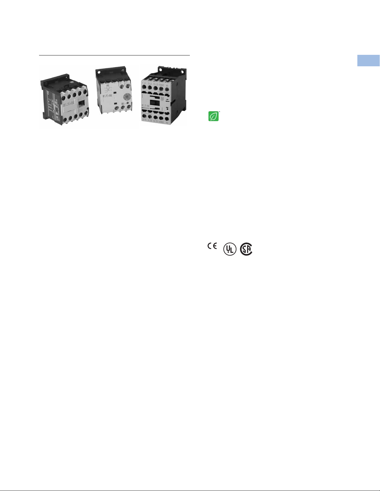
Product Description
Eaton’s new line of XT relays
and timers includes mini and
standard frame control relays
and auxiliary contacts, mini
electronic on-delay and
multi-function timers and
an electronic star-delta
(wye-delta) timer for use
in star-delta (wye-delta)
combinations. Because XT
meets UL
standards, it is the perfect
product solution for IEC
applications all over the
world. The compact, space
saving and easy to install XT
line of IEC contactors and
starters is the efficient and
effective solution for
customer applications.
®
, CSA® and CE
Features
●
For use with mini and
standard frame size
contactors and starters
●
Control relays
●
AC control from 12V to
550V 50 Hz, 600V 60 Hz
●
DC control from
12V to 220V
●
On-delay and multifunction timers
●
24–240 Vac/Vdc control
●
Available with screw or
spring cage terminals
●
Four-pole configurations
●
IP20 finger and back-ofhand proof
●
Large ambient temperature
range: –25° to 50°C [–13°
to 122°F]
●
The XTRE control relays
have positively driven
contacts between the relay
and the auxiliary contact
modules as well as within
the auxiliary contact
modules
Contents
Description Page
Relays and Timers
Catalog Number Selection . . . . . . . . . . . . . . . . V5-T1-4
Product Selection . . . . . . . . . . . . . . . . . . . . . . . V5-T1-5
Accessories . . . . . . . . . . . . . . . . . . . . . . . . . . . V5-T1-6
Technical Data and Specifications . . . . . . . . . . V5-T1-12
Dimensions . . . . . . . . . . . . . . . . . . . . . . . . . . . V5-T1-16
Miniature Controls . . . . . . . . . . . . . . . . . . . . . . . . . V5-T1-18
Contactors and Starters . . . . . . . . . . . . . . . . . . . . V5-T1-35
Thermal Overload Relays . . . . . . . . . . . . . . . . . . . . V5-T1-128
C440/XT Electronic Overload Relay . . . . . . . . . . . . V5-T1-141
Manual Motor Protectors . . . . . . . . . . . . . . . . . . . V5-T1-157
Combination Motor Controllers . . . . . . . . . . . . . . . V5-T1-193
XT Electronic Manual Motor Protector . . . . . . . . . V5-T1-216
EMS—Electronic Motor Starter . . . . . . . . . . . . . . . V5-T1-229
Reference Data . . . . . . . . . . . . . . . . . . . . . . . . . . . V5-T1-231
Standards and Certifications
●
IEC EN 60947
●
CE approved
●
UL
●
CSA
Instructional Leaflets
Pub51219 XTRM Mini Control Relays
Pub51210 XTRE Control Relays
Pub51244 XTTR Electronic Star-Delta (Wye-Delta) Timer
Pub51245 XTMT Mini Electronic On-Delay and
Multi-Function Timers
1
1
1
1
1
1
1
1
1
1
1
1
1
1
1
1
1
1
1
1
1
1
1
1
1
1
1
1
1
1
Volume 5—Motor Control and Protection CA08100006E—November 2015 V5-T1-3
Page 2
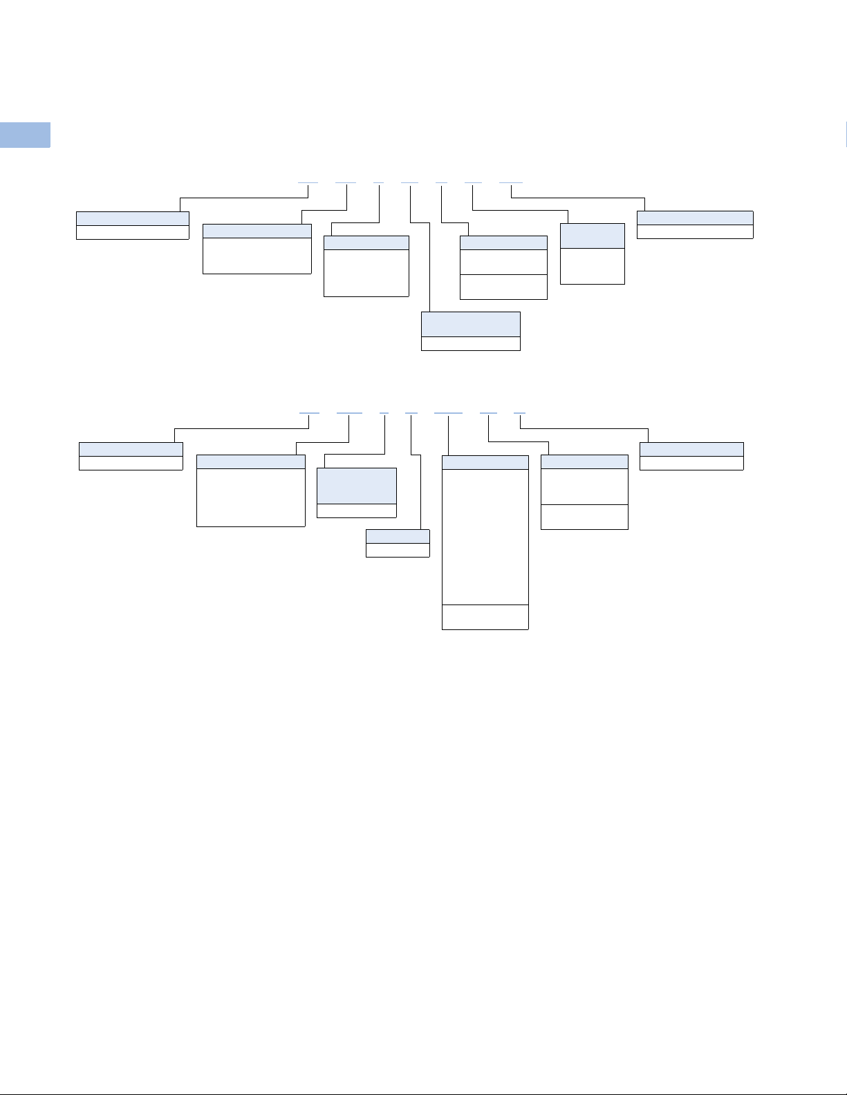
1.1
XT RE C 10 B 22 AD
Product Family Code
RM = Mini IEC control
relay
RE = IEC control relay
Coil Code
See table on Page V5-T1-5.
Product Line Prefix
XT = XT IEC power control
Terminations
Blank =Screw
terminals
C = Spring cage
terminals
Conventional Thermal
Current Rating
10 = 10A
Frame
XTRM
A = 45 mm—mini
XTRE
B = 45 mm—standard
Contact
Configuration
40 = 4NO
31 = 3NO-1NC
22 = 2NO-2NC
Product Family Code
MT = Mini IEC timing
relay
TR = Electronic timing
relay star-delta
(wye-delta)
Coil Code
B = 24–240 Vac/Vdc
Product Line Prefix
XT = XT IEC power control
Function
XTMT
11 = On-delay
70 = Adjustable
XTTE
51 = Star-delta
Time Range Max.
XTMT
30S = 1.5–30s
60H = 05–1s
0.15–3s
0.5–10s
3–60s
0.15–3 min
0.5–3 min
3–60 min
0.15–3h
0.5–3h
3–60h
XTTR
60S =3–60s
XT MT 6 B 30S 11 B
Conventional
Thermal Current
Rating
6 = 6A
Frame
A = 45 mm
Catalog Number Selection
1
XT—Relays
1
1
1
1
1
1
1
1
XT—Timers
1
1
IEC Contactors and Starters
XT IEC Power Control
1
1
1
1
1
1
1
1
1
1
1
1
1
1
1
1
1
1
1
V5-T1-4 Volume 5—Motor Control and Protection CA08100006E—November 2015
Page 3

IEC Contactors and Starters
XTRM10A_
14
13 333443
44
A1
A2
23
24
14
13 2122333443
44
A1
A2
14
13
21
2231324344
A1
A2
XTREC10_
14
13 333443
44
A1
A2
23
24
14
13 2122333443
44
A1
A2
14
13
21
2231324344
A1
A2
XT IEC Power Control
1.1
Product Selection
When Ordering
●
Orders must be placed in multiples of the package quantity listed
●
DC operated control relays have a built-in suppressor circuit
●
Contact terminal numbers to EN50011
●
Coil terminal numbers to EN50005
Mini Control Relays
Conventional
Thermal
(A)
Current I
th
10 4NO 6 3 1.5 XTRM10A40_
10 3NO-1NC 6 3 1.5 XTRM10A31_
10 2NO-2NC 6 3 1.5 XTRM10A22_
Contact
Configuration
Control Relays
Conventional
Thermal
Current Open
at 60°C I
16 4NO 6 4 1.5 XTRE10B40_ XTREC10B40_
th
(A)
Contact
Configuration
Rated Operational Current
(A)
AC-15 I
e
220–240V 380–415V 500V
Rated Operational Current
(A)
AC-15 I
e
220–240V 380–415V 500V
Circuit
Symbol
Circuit
Symbol
Screw Terminal
Catalog Number
1
Screw Terminal
Catalog Number
2
Spring Cage
Ter mi na l
Catalog Number
1
1
1
1
1
1
1
1
1
1
1
1
1
1
1
1
1
1
16 3NO-1NC 6 4 1.5 XTRE10B31_ XTREC10B31_
16 2NO-2NC 6 4 1.5 XTRE10B22_
3
XTREC10B22_
3
Coil Voltage Suffix
Coil Voltage Suffix Code Coil Voltage Suffix Code Coil Voltage Suffix Code Coil Voltage Suffix Code
110V 50 Hz, 120V 60 Hz
220V 50 Hz, 240V 60 Hz
230V 50 Hz
24V 50/60 Hz
24 Vdc
Notes
1
Underscore (_) indicates magnet coil suffix required. See Coil Voltage Suffix table above.
2
DC operated control relays XTRM(C)10A22_ cannot be used with front mount auxiliary contacts.
3
DC operated control relays XTRE(C)10B22_ can only be combined with two-pole auxiliary contacts.
A
B
F
T
TD
415V 50 Hz, 480V 60 Hz
550V 50 Hz, 600V 60 Hz
208V 60 Hz
190V 50 Hz, 220V 60 Hz
240V 50 Hz, 277V 60 Hz
C
D
E
G
H
380V 50 Hz, 440V 60 Hz
380V 60 Hz
12V 50/60 Hz
42V 50 Hz, 48V 60 Hz
48V 50 Hz
L
P
R
W
Y
120 Vdc
220 Vdc
12 Vdc
48 Vdc
AD
BD
RD
WD
1
1
1
1
1
1
1
1
1
1
1
1
1
1
Volume 5—Motor Control and Protection CA08100006E—November 2015 V5-T1-5
 Loading...