

Cutler Hammer, Div of Eaton Corp TR timing relays Catalog
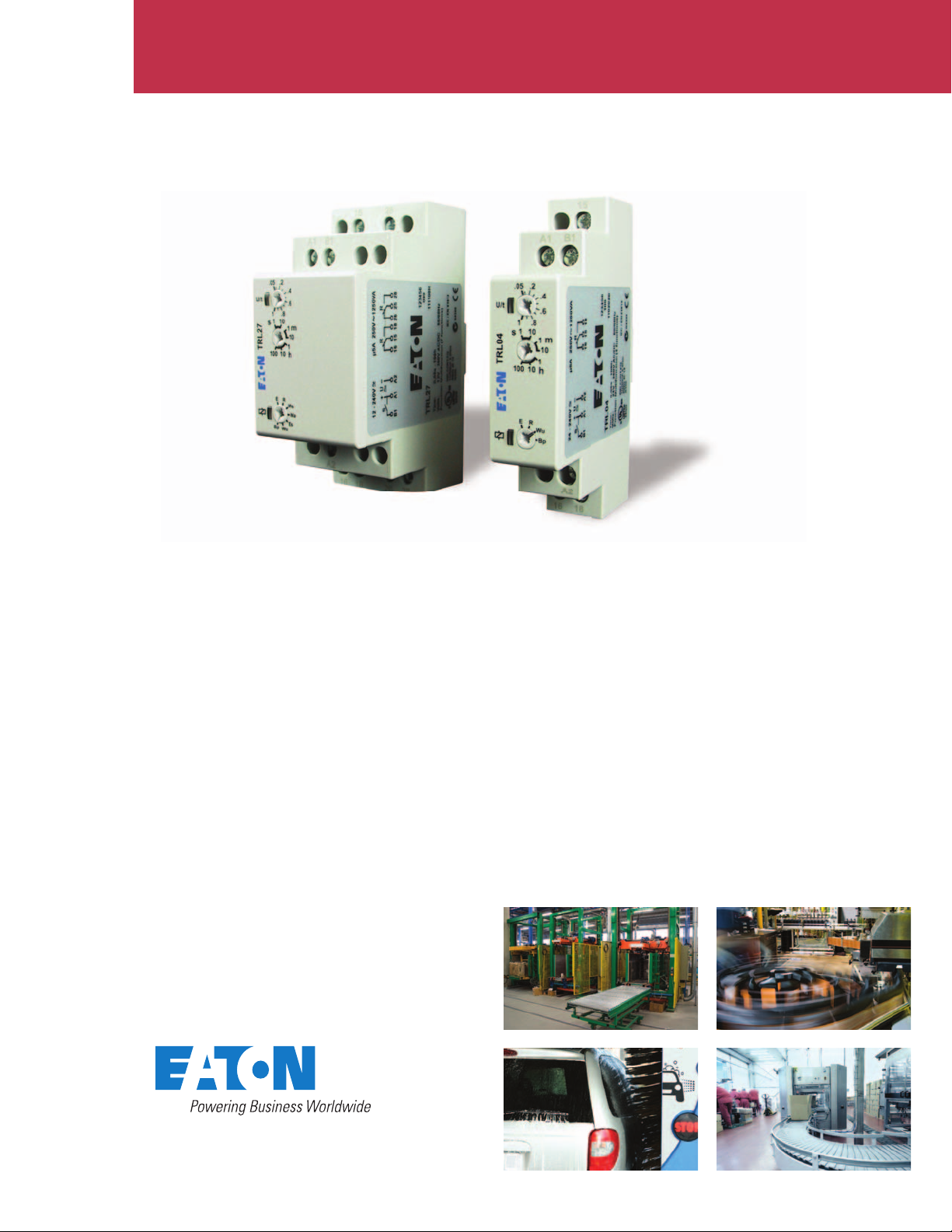
Universal Series timers
TR timing relays
Eaton’s Universal TR Series timers are a versatile and
cost-competitive family of timing relays. The compact
IEC-style housing installs easily onto a standard DIN rail,
and the direct-wire design eliminates the need for
additional sockets and accessories. Each timer has multiple
user-selectable timing functions and timing ranges, and a
universal input voltage of either 12 or 24 volts to 240 volts
AC or DC, depending on the model.
Reducing your inventory costs
With up to seven selectable
timing functions and seven
selectable time ranges from
50 milliseconds to 100 hours,
you can meet the needs of
almost any application with
just one or two stock items.
Do you need 24 Vdc control in
some cases and 120 V
in others? You are covered with
the Universal TR Series timer, as
it has a universal, self-selecting
control voltage input range from
either 12 or 24 volts (depending
on model) to 240 volts AC or
DC. Are you tired of buying
minimum quantities of sockets
and accessories for your plug-in
timing relays? The direct wire
design of the Universal TR
Series gives you everything
youneed in a single item.
ac control
Reducing your labor costs
During initial installation, the
large terminals on the Universal
TR Series make wiring quick
and easy
even allows easy access to the
bottom terminals when the top
wires are installed. The easy-toread set point markings improve
the accuracy of setup, thereby
reducing your startup time. Are
you spending too much time
troubleshooting and replacing
timers? The dual LED indicators
on the Universal TR Series use
multiple modes to signal input
power, relay state and timing
status. The Universal TR Series
also features a high-quality
design with twice the relay life
of many competitors.
. The offset design
Specifi cations
F
Universal TR Timing Relays
Specification TRL04 TRL07 TRL27 TRW27
Functions
Time range
Input
Supply voltage
Duty cycle
Output
Contact configuration
Rated voltage
Switching capacity
Mechanical life
Electrical life
Accuracy
Base accuracy
Adjustment accuracy
Repetition accuracy
Physical
Ambient temperature
8, 9, 10, 14
0.05 sec to 100 hours
24 to 240 Vac/dc
100%
SPDT (one changeover contact)
250 Vac
2000 VA (8A/250V)
20 x 10^6 operations
2 x 10^5 operations at 1000 VA
load, resistive
±1% of maximum scale value
<5% of maximum scale value
<0.5% or ±5 ms
8, 9, 10, 11, 12, 13, 14
0.05 sec to 100 hours
24 to 240 Vac/dc
100%
SPDT (one changeover contact)
250 Vac
2000 VA (8A/250V)
20 x 10^6 operations
2 x 10^5 operations at 1000 VA
load, resistive
±1% of maximum scale value
<5% of maximum scale value
<0.5% or ±5 ms
8, 9, 10, 11, 12, 13, 14
0.05 sec to 100 hours
12 to 240 Vac/dc
100%
DPDT (two changeover contacts)
250 Vac
2000 VA (8A/250V)
20 x 10^6 operations
2 x 10^5 operations at 1000 VA
load, resistive
±1% of maximum scale value
<5% of maximum scale value
<0.5% or ±5 ms
1, 2, 3, 4, 5, 6, 7
0.05 sec to 100 hours
12 to 240 Vac/dc
100%
DPDT (two changeover contacts)
250 Vac
2000 VA (8A/250V)
20 x 10^6 operations
2 x 10^5 operations at 1000 VA
load, resistive
±1% of maximum scale value
<5% of maximum scale value
<0.5% or ±5 ms
–25 to +55°C –25 to +55°C –25 to +55°C –25 to +55°C
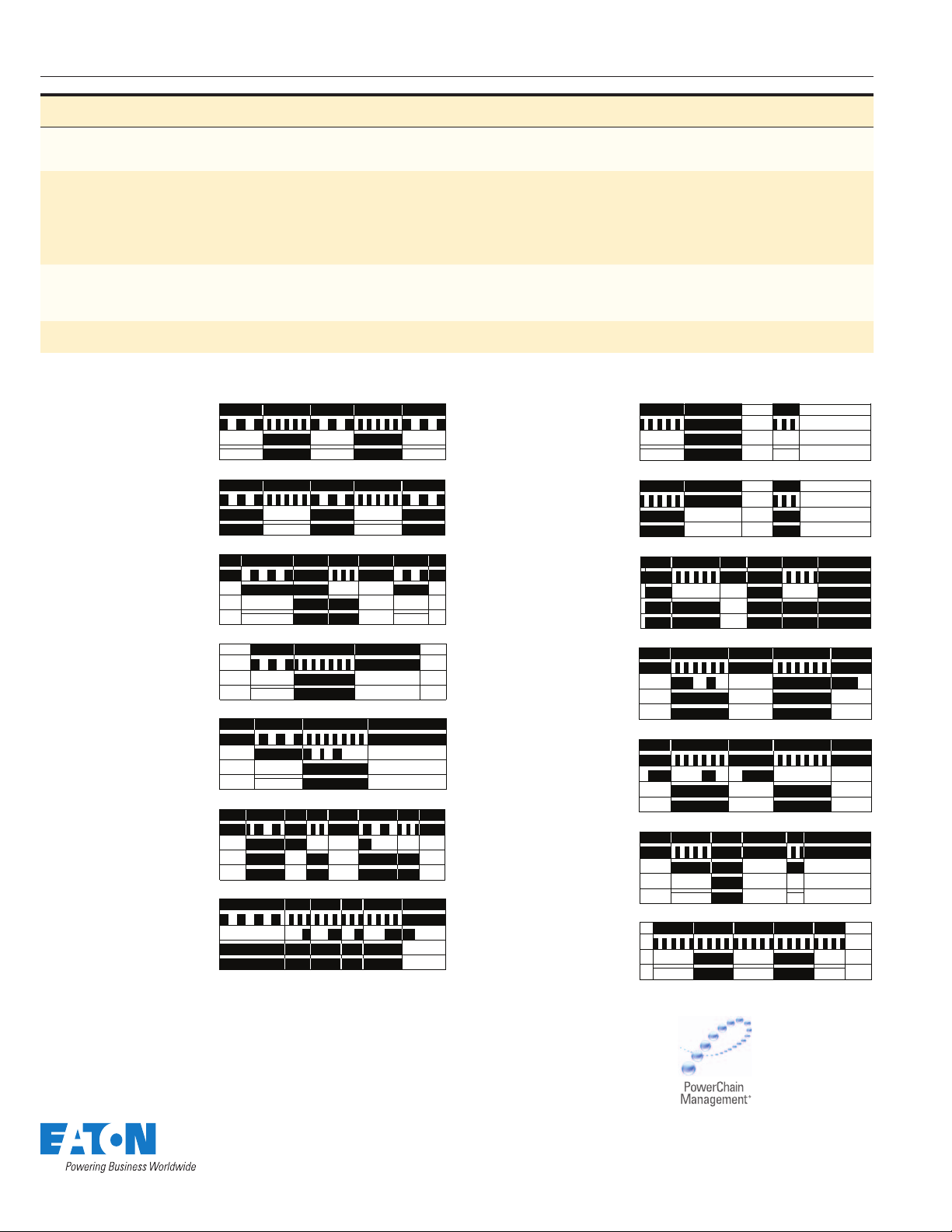
Timer Function Descriptions
unction #1—
Asymmetrical
Flasher,
Pause First (lp)
Input Power (U)
LED U/t*
Output LED**
Output Relay (R)
t2t1 t1 t1t2
Function #8—
ON Delay, Power
Triggered (E)
Input Power (U)
LED U/t*
Output LED**
Output Relay (R)
t<t
Function #2—
Asymmetrical
Flasher,
Pulse First (li)
Function #3—
ON Delay and
OFF Delay with
Control Contact (ER)
Function #4—
ON Delay and Single
Shot Leading Edge
Voltage Controlled
(EWu)
Function #5—
ON Delay and Single
Shot Leading Edge
Control Contact
(EWs)
Function #6—
Single Shot Leading
and Single Shot
Trailing Edge with
Control Contact
(WsWa)
Function #7—
Pulse Sequence
Monitoring (Wt)
Input Power (U)
LED U/t*
Output LED**
Output Relay (R)
Input Power (U)
LED U/t*
Trigger Signal (S)
Output LED**
Output Relay (R)
Input Power (U)
LED U/t*
Output LED**
Output Relay (R)
Input Power (U)
LED U/t*
Trigger Signal (S)
Output LED**
Output Relay (R)
Input Power (U)
LED U/t*
Trigger Signal (S)
Output LED**
Output Relay (R)
Input Power (U)
LED U/t*
Trigger Signal (S)
Output LED**
Output Relay (R)
t2t1 t1 t1t2
t1 <t1t2
t1 t2
t1 t2
t1 <t2 <t2 t2<t2
Function #9—
Single Shot Leading
Edge Voltage
Controlled (Wu)
Function #10—
OFF Delay/Signal
OFF Delay (R)
Function #11—
Single Shot
Leading Edge with
Control Input (Ws)
Function #12—
Single Shot Trailing
Edge with Control
Input (Wa)
Function #13—
ON Delay Control
t2t2t1 t1
Signal Start,
Trailing Edge OFF
(Es)
Function #14—
Flasher,
Pause First (Bp)
Input Power (U)
LED U/t*
Output LED**
Output Relay (R)
Input Power (U)
LED U/t*
Trigger Signal (S)
Output LED**
Output Relay (R)
Input Power (U)
LED U/t*
Trigger Signal (S)
Output LED**
Output Relay (R)
Input Power (U)
LED U/t*
Trigger Signal (S)
Output LED**
Output Relay (R)
Input Power (U)
LED U/t*
Trigger Signal (S)
Output LED**
Output Relay (R)
Input Power (U)
LED U/t*
Output LED**
Output Relay (R)
t<t
<tt
tt
tt
t<t
t <ttttt
PowerChain Management is a registered
trademark of Eaton Corporation.
All other trademarks are property of their
respective owners.
 Loading...