

Page 1
Molded Case Circuit Breakers
Power Defense Molded Case Circuit Breakers—Frame Size 4
Power Defense Molded Case Circ uit Breakers
2.2
Contents
Description Page
Power Defense Molded Case Circuit Breakers
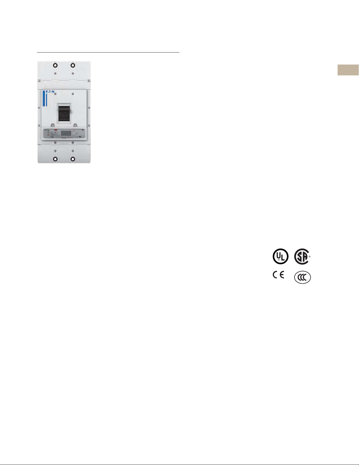
Power Defense Molded Case Circuit Breakers—Frame Size 4
Product Description
Frame Size 4 covers a range
of 300 A through 800 A with
a complete offering of trip
units, including PXR
electronic trip units and fixedadjustable thermal-magnetic
trip units. PD-4 is available in
a single 800 A frame.
Application Description
Frame Size 4 can be used to
meet a wide range of circuit
protection and power
distribution needs, including
ground fault protection and
100% UL ratings. PXR trip
units in PD-4 provide all levels
of protection, including
energy metering with
multiple communication
schemes, breaker health
indication and arc flash
reduction options.
Features and Benefits
Frame Size 4 breakers are
modular and available as
complete breakers from the
factory or as modular
components, including
frames, trip units,
accessories and terminals
to provide flexibility for
customers. PXR trip units
are available with advanced
features to provide
customers unparalleled
situational awareness of
their electrical system.
Frame Size 1 (15–125 A) . . . . . . . . . . . . . . . . . . . V4-T2-22
Frame Size 2 (15–225 A) . . . . . . . . . . . . . . . . . . . V4-T2-29
Frame Size 3 (45–600 A) . . . . . . . . . . . . . . . . . . . V4-T2-42
Frame Size 4 (300–800 A)
Catalog Number / Product Selection . . . . . . V4-T2-58
Accessories . . . . . . . . . . . . . . . . . . . . . . . . . V4-T2-63
Dimensions and Weights . . . . . . . . . . . . . . . V4-T2-69
Frame Size 5 (320–1200 A) . . . . . . . . . . . . . . . . . V4-T2-70
Frame Size 6 (700–2500 A) . . . . . . . . . . . . . . . . . V4-T2-79
Motor Circuit Protectors (3–600 A) . . . . . . . . . . . V4-T2-87
Motor Protection Circuit Breakers (15–600 A). . . V4-T2-98
Terminals, Lugs and Connectors . . . . . . . . . . . . V4-T2-104
Communications and Software . . . . . . . . . . . . . . V4-T2-127
Special Applications. . . . . . . . . . . . . . . . . . . . . . . V4-T2-129
Standards and Certifications
Power Defense breakers are
designed and tested to meet
stringent requirements for:
l
UL
l
CSA
l
IEC (CE)
l
CB (CCC)
2
2
2
2
2
2
2
2
2
2
2
2
2
2
2
2
2
2
2
2
2
2
2
2
2
2
2
2
2
2
Volume 4—Circuit Protection CA08100005E—March 2020 V4-T2-57
Page 2
Molded Case Circuit Breakers
Frame
Size
4 =4
Pole
Options
2 =2-pole
3 =3-pole
4 = 4-pole (100% N)
0 = 4-pole (0% N)
6 = 4-pole (60% N)
Interrupting
Ratings
G = 35 kA at 480 V
K = 50 kA at 480 V
M= 65 kA at 480 V
Canada
G = 18 kA at 600 V
K = 25 kA at 600 V
M= 35 kA at 600 V
Trip Unit
Type Options
TFA = Fixed thermal /
Adjustable magnetic
VFA = 50 °C Fixed thermal /
Adjustable magnetic
(non UL)
Standard Terminal
Options
N = No terminals
J = Line and load terminals
K = Line only terminals
L = Load only terminals
Continuous
Current Ratings
0300 = 300 A
2
0350 = 350 A
2
0400 = 400 A
2
0450 = 450 A
2
0500 = 500 A
0600 = 600 A
0700 = 700 A
0800 = 800 A
Product Series
PD = Power Defense
4 =4 2 =2-pole
3 =3-pole
4 =4-pole
G = 35 kA at 480 V
M= 65 kA at 480 V
G = 18 kA at 600 V
M= 35 kA at 600 V
KNS = Molded Case Switch N = No terminals
J = Line and load terminals
K = Line only terminals
L = Load only terminals
0800 = 800 APD
PD G 4 3 M 0800 TFA J
Certifications/
Standards
G = UL/CSA/IEC/CCC
Molded Case Switches—Globally Rated
3
G = UL/CSA/IEC/CCC
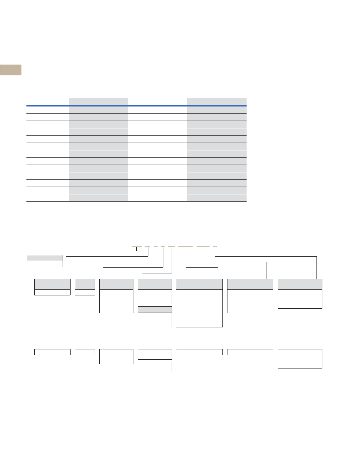
2.2
Catalog Number / Product Selection
2
Power Defense—Frame Size 4 (300–800 A)
2
Frame Size 4 covers a range of 320 A through 800 A using electronic trip units, and 300 A through
800 A using thermal-magnetic trip units. It is available in configurations of 2-pole, 3-pole and 4-pole,
with the 2-pole being in the same physical size of a 3-pole variant.
2
Interrupting Ratings
2
2
ANSI (UL/CSA)
240 Vac 65 85 100
2
480 Vac
600 Vac
2
2
2
2
2
2
1
250 Vdc
IEC
240 Vac 55 55 85 85 100 100
380–415 Vac
440 Vac
480 Vac
525 Vac
660–690 Vac
1
250 Vdc
Power Defense Molded Case Circuit Breakers
GKM
kA rms kA rms kA rms
35 50 65
18 25 35
22 22 25
l
cu
36 36 50 50 70 53
30 22.5 35 35 50 40
25 20 35 22.5 50 30
20 16.5 25 20 30 25
8 410515 7.5
22 22 22 22 25 25
l
cs
l
cu
l
cs
l
cu
l
cs
Power Defense—Frame Size 4 (300–800 A)
2
This information is presented as a tool to develop catalog numbers
for selecting Power Defense circuit breakers and trip units.
2
Molded Case Circuit Breakers with Thermal-Magnetic Trip Units (TMTU)—Globally Rated
2
2
2
2
2
2
2
2
2
2
2
2
Notes
1
2
2
3
2
2
DC ratings available in thermal-magnetic breakers only. 250 Vdc is achieved using 2 poles in series.
Not available in 4-pole 60% neutral protection.
Molded case switch may open above 6000 A.
2
V4-T2-58 Volume 4—Circuit Protection CA08100005E—March 2020
Page 3
Molded Case Circuit Breakers
Frame
Size
4 =4
Pole
Options
2 =2-pole
3 =3-pole
4 =
4-pole
(programmable N)
Interrupting
Ratings
G = 35 kA at 480 V
K = 50 kA at 480 V
M= 65 kA at 480 V
G = 18 kA at 600 V
K = 25 kA at 600 V
M= 35 kA at 600 V
Trip Unit
Type Options
B2N = PXR 10 LSI
E##
1
=PXR 20
D##
1
=PXR 20D
P##
1
=PXR 25
Standard Terminal
Options
N = No terminals
J = Line and load terminals
K = Line only terminals
L = Load only terminals
Continuous
Current Ratings
0800 = 800 A
Product Series
PD = Power Defense
4 =4 3 =3-pole
4 =
4-pole
(programmable N)
G = 35 kA at 600 V
K = 50 kA at 600 V
M= 65 kA at 600 V
G = 18 kA at 600 V
K = 25 kA at 600 V
M= 35 kA at 600 V
B2N = PXR 10 LSI
E##
1
=PXR 20
D##
1
=PXR 20D
P##
1
=PXR 25
N = No terminals
J = Line and load terminals
K = Line only terminals
L = Load only terminals
0800 = 800 APD
PD G 4 3 M 0800 P2M J
Certifications/
Standards
G = UL/CSA/IEC/CCC
Molded Case Circuit Breakers with PXR ETU—Globally Rated (100% UL Rated)
F = UL/CSA/IEC/CCC
(100% UL Rated)
Frame
Size
4 =4
Pole
Options
2 =2-pole
3 =3-pole
4 =4-pole
Interrupting
Ratings
G = 35 kA at 480 V
K = 50 kA at 480 V
M= 65 kA at 480 V
Canada
G = 18 kA at 600 V
K = 25 kA at 600 V
M= 35 kA at 600 V
Trip Unit
Type Options
FNN = Frame Only
Standard Terminal
Options
N = No terminals
Continuous
Current Ratings
0800 = 800 A
Product Series
PD = Power Defense
4 =4 3 =3-pole
4 =4-pole
G = 35 kA at 480 V
K = 50 kA at 480 V
M= 65 kA at 480 V
G = 18 kA at 600 V
K = 25 kA at 600 V
M= 35 kA at 600 V
FNN = Frame Only N = No terminals0800 = 800 APD
PD G 4 3 M 0800 FNN J
Certifications/
Standards
G = UL/CSA/IEC/CCC
Frame Only—Globally Rated (100% UL Rated)
F = UL/CSA/IEC/CCC
(100% UL Rated)
Power Defense Molded Case Circ uit Breakers
2.2
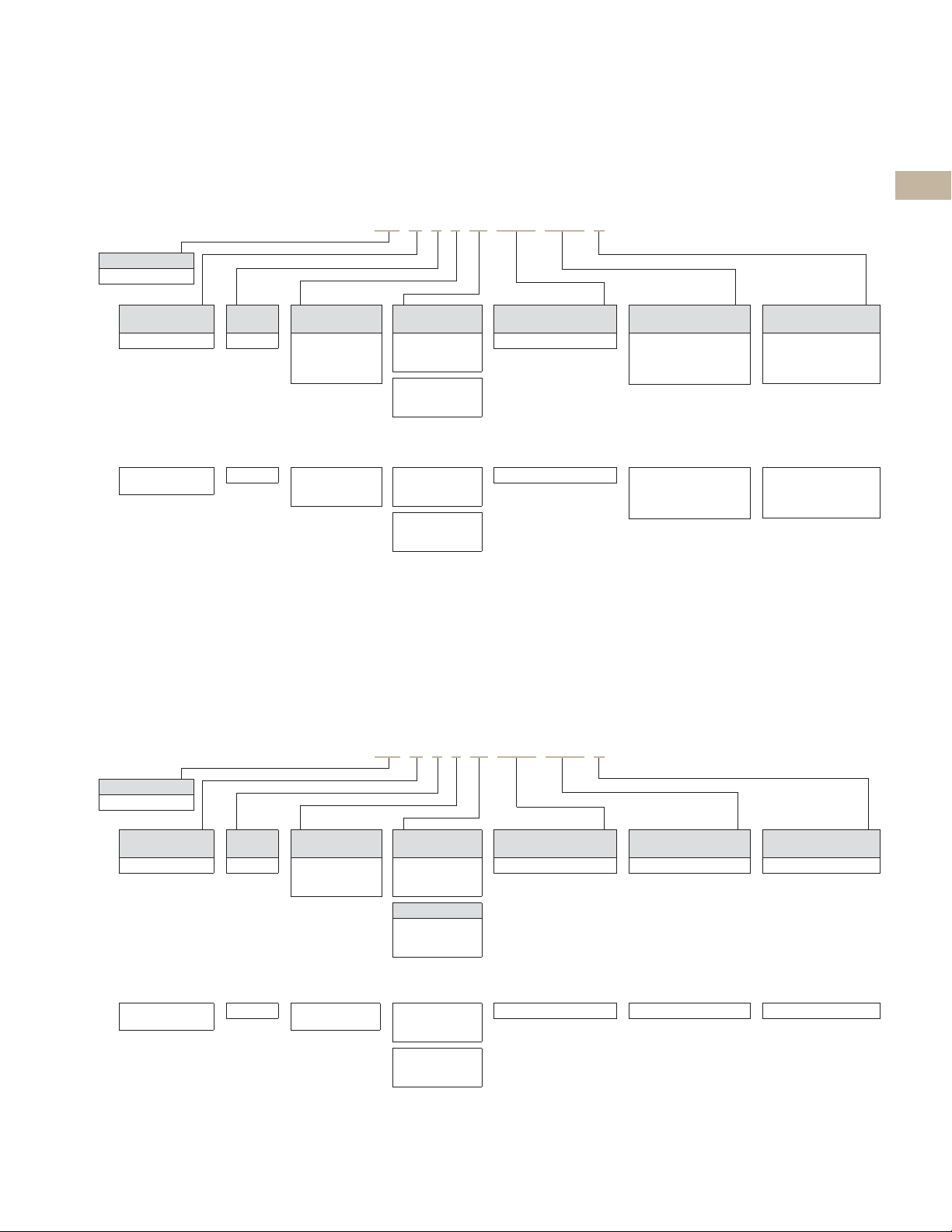
Molded Case Circuit Breakers with Power Xpert Release (PXR) Electronic Trip Units (ETU)
This information is presented as a tool to develop catalog numbers for selecting Power Defense
circuit breakers and trip units.
Molded Case Circuit Breakers with PXR ETU—Globally Rated
Globally Rated Frame Only
PD-4 thermal-magnetic and electronic breakers may also be purchased as separate frames, trip units,
terminals and accessories for field configuration of a final breaker. Each Frame Only device is marked
with interrupting ratings and a maximum continuous current rating; each trip unit is also marked with a
maximum continuous current rating, which must not exceed that of the frame. Additionally, 100% UL
Rated frames are marked as such on the Frame Only device.
This information is presented as a tool to develop catalog numbers for selecting Power Defense
circuit breakers and trip units.
Frame Only—Globally Rated
2
2
2
2
2
2
2
2
2
2
2
2
2
2
2
2
2
2
Note
1
See tables and descriptions on Page V4-T2-61 for protection type (#
) and available configured options (#
(1)
Volume 4—Circuit Protection CA08100005E—March 2020 V4-T2-59
).
(2)
2
2
2
2
2
2
2
2
2
2
2
2
Page 4
Molded Case Circuit Breakers
Frame
Size
4 =4
Separator
Digit
X = Accessory
Trip Unit
Type Options
TFA = Fixed Thermal /
Adjustable Magnetic
VFA = 50 °C Fixed Thermal /
Adjustable Magnetic
(non UL)
Continuous
Current Ratings
0300 = 300 A
1
0350 = 350 A
1
0400 = 400 A
1
0450 = 450 A
1
0500 = 500 A
0600 = 600 A
0700 = 700 A
0800 = 800 A
Product Series
PD = Power Defense
PD G 4 X TFA 3 0800
Certifications/
Standards
G = UL/CSA/IEC/CCC
Pole
Options
2 = 2-pole
3 = 3-pole
4 = 4-pole (100% N)
0 = 4-pole (0% N)
6 = 4-pole (60% N)
Frame
Size
4 =4
Separator
Digit
X = Accessory
Trip Unit
Type Designator
PXR = Power Xpert Release
Trip Unit
Continuous
Current Ratings
0800 = 800 A
Product Series
PD = Power Defense
PD G 4 X PXR 3 0800 E2N
Certifications/
Standards
G = UL/CSA/IEC/CCC
Pole
Options
3 = 3-pole
4 = 4-pole
(programmable N)
Trip Unit
Type and Options
B2N = PXR 10 LSI
E##
2
=PXR 20
D##
2
=PXR 20D
P##
2
=PXR 25
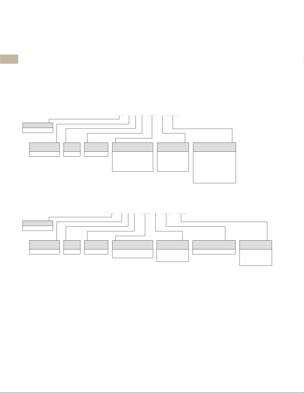
2.2
Trip Units
2
PD-4 thermal-magnetic and electronic breakers may also be purchased as separate
frames, trip units, terminals and accessories for field configuration of a final breaker.
2
For two-pole breakers using electronic trip units, three-pole trip units are used.
PDG designated trip units are for use with PDG and PDF breaker frames. The 100%
2
rating for PDF (100% UL Rated) is marked on the frame, not the trip unit.
2
Trip Units Only
This information is presented as a tool to develop catalog numbers
2
for selecting Power Defense circuit breakers and trip units.
2
Thermal-Magnetic Trip Units
2
2
2
2
2
Power Defense Molded Case Circuit Breakers
2
2
2
Power Xpert Release (PXR) Electronic Trip Units
2
Power Xpert Release (PXR) Electronic Trip Units
2
2
2
2
2
2
Notes
2
1
Not available in 4-pole 60% neutral protection.
2
2
See tables and descriptions on Page V4-T2-61 for protection type (#
2
2
) and available configured options (#
(1)
).
(2)
2
2
2
2
2
V4-T2-60 Volume 4—Circuit Protection CA08100005E—March 2020
Page 5

Molded Case Circuit Breakers
Power Defense Molded Case Circ uit Breakers
2.2
Power Xpert Release (PXR) Trip Unit Options—Frame Size 4
Power Xpert Release (PXR) Trip Unit Options
#
—Protection Type #
(1)
PXR ETU
PXR 10 B
PXR 20 E
PXR 20D D
PXR 25 P
Descriptions of PXR Configured Options
Relays—2 Form A contacts
(rated for 240 Vac, 1 A)
l
Interface: 3 wires (ALM1,
ALM2, ALM Common)
l
Programmable to indicate
breaker conditions
Modbus—Modbus RTU
directly from breaker
l
Interface:
MODBB, MODBG)
l
No additional modules
required
Available Continuous Current (l
Option Setting 800 A
PXR 10, PXR 20 1 320 A
PXR 20D, PXR 25 Programmable from minimum to maximum values in 10 A increments.
LSI LSIG
2 —— — N ————————
2 —— — NRMZ CWX ——
— 34 5 — RMZCWX——
234 5 ——M ——W — DY
234 5 ——M ——W — DY
3 wires (MODBA,
2 350 A
3 400 A
4 450 A
5 500 A
6 550 A
7 600 A
8 630 A
9 700 A
10 = l
n
LSI with
ARMS
Catalog Number Selection and Maximum Setting (ln)
800 A
LSIG with
ARMS
ZSI—Zone Selective
Interlocking
l
Interface: 3 wires
(Zin, Zout, Zcomm)
l
Includes ability to turn
ON and OFF, and
indicate signals
CAM—CAM Link connection
(requires a CAM module per
breaker)
l
Interface: 5 wires (refer to
CAM IL for details)
l
Communications Adapter
Modules available for
Modbus TCP and PROFIBUS
) Settings on PXR Electronic Trip Units
r
—Available Configured Options
(2)
—
—
—
—
Relays
—
—
—
Relays
Modbus
—
—
ARMS—Arcflash Reduction
Maintenance System, or
Maintenance Mode
l
Available as trip unit
Protection Type 4 or 5
l
Interface: Switch and LED
on face of trip unit and two
wires for remote switch
enable option
(24 Vdc required)
l
A programmable relay will
be factory defaulted to
remote indication of ARMS
Relays
—
ZSI
—
Relays
—
—
CAM
Relays
Modbus
ZSI
—
Relays
—
ZSI
CAM
Auxiliary Power
l
Connection included with
all PXR 20, 20D, and 25
trip units
l
Required for
communications, relays,
and metering accuracy
l
24 Vdc, 0.5 A
l
Interface: 2 wires
(Aux +24 V, Aux 0 V)
Relays
Modbus
—
CAM
Relays
Modbus
ZSI
CAM
2
2
2
2
2
2
2
2
2
2
2
2
2
2
2
2
2
2
2
2
2
2
2
2
Volume 4—Circuit Protection CA08100005E—March 2020 V4-T2-61
2
2
2
2
2
2
Page 6

Molded Case Circuit Breakers
2.2
Terminals—Frame Size 4
2
Catalog numbers shown are for a single side of a 3-pole breaker.
For Frame Size 4, terminals are also available in single-pole kits; these are not
2
available in 2-pole or 4-pole configurations, unless otherwise noted.
For single terminals, replace X3 with X1 on the catalog number.
2
Example: PDG4X3TA800 becomes PDG4X1TA800 for a single unit.
Te r m i n a l Ty p e s
2
2
2
2
2
2
PDG4X3TA700
PDG4X3T600
2
PDG4X3TA700CW
2
Note: Pictures are for reference only.
Power Defense Molded Case Circuit Breakers
PDG4X3TA800
PDG4X3TA800SW
PDG4X3TA800CW
PDG4X3TA801
PDG4X3T800
PDG4X3TA801CW
PDG4X3TA800RF
2
Te r m i n a l s
2
Maximum
Breaker
Amperes
2
Standard Terminals
2
700 Aluminum Cu/Al B, C 2 1–500 42.4–253 PDG4X3TA700 — J K L 300–700
800 Aluminum Cu/Al B, C 3 3/0–400 85–203 PDG4X3TA800 — J K L 800
2
Alternate Terminals
800 Aluminum Cu/Al B, C 2 500–750 253–380 PDG4X3TA801 — T U V 300–800
2
Non-Aluminum Terminals
600 Aluminum Cu B, C 2 2/0–500 67.4–238 PDG4X3T600 — W Y Z 300–600
2
800 Aluminum Cu B, C 3 3/0–300 85–152 PDG4X3T800 — W Y Z 700–800
2
StrandAble Terminals
800 Aluminum Cu/Al B, C 3 3/0–400 85–203 PDG4X3TA800SW — A B C 300–800
2
2
Control Wire Terminals
700 Aluminum Cu/Al B, C 2 1–500 42.4–253 PDG4X3TA700CW — 1 2 3 300–700
2
800 Aluminum Cu/Al B, C 3 3/0–400 85–203 PDG4X3TA800CW — 1 2 3 800
800 Aluminum Cu/Al B, C 2 500–750 253–380 PDG4X3TA801CW — 4 5 6 300–800
2
Rear Fed Terminals
2
800 Aluminum Cu/Al B, C 3 3/0–300 85–152 PDG4X3TA800RF Interphase
2
Rear Connectors
800 — ——— — — PDG4X3T800RC — R — — 300–800
2
End Cap Kits/Screw Terminals
800 — ——— — — PDG4X3TS800
2
Notes
2
Wire capacity is based on standard imperial wire sizes; metric sizes provided in table are a direct
conversion to demonstrate maximum capacity, not to denote metric wire sizes.
1
2
Terminal
Body Type
End cap kits are available in 3-pole and 4-pole configurations only.
For 4-pole, use catalog number PDG4X4TS800.
Wire
Typ e
Wire
Class
D, G, H, I,
K, M
Number of
Conductors
per Phase
AWG / kcmil
Range per
Conductor
3/0–300 85–152
Metric (mm
Range per
Conductor
2
)
3-Pole
Catalog Number
Included
Accessories
barriers
1
— S D E 300–800
Digit 14 Designation Factory
Line and
Load
— — — 300–800
Line
Only
2
Load
Only
Config.
Ampere
Range
V4-T2-62 Volume 4—Circuit Protection CA08100005E—March 2020
Page 7

Molded Case Circuit Breakers
Power Defense Molded Case Circ uit Breakers
2.2
Accessories
Internal Accessory Configurations—Frame Size 4
3-Pole Circuit Breakers 4-Pole Circuit Breakers
Tripping
Accessory
Options
None None None
Shunt Trip 1NO (1 space) 1NO (1 space)
UVR 2NC (2 spaces) 2NC (2 spaces)
Alarm Options
(1–2 spaces)
1NC (1 space) 1NC (1 space)
1NO/1NC (2 spaces) 1NO/1NC (2 spaces)
2NO (2 spaces) 2NO (2 spaces)
1
Aux Options
(4 spaces)
2CO (4 spaces)
4NO (4 spaces)
4NC (4 spaces)
Tripping
Accessory
Options
None None None
Shunt Trip 1NO (1 space) 1NO (1 space)
UVR 2NC (2 spaces) 2NC (2 spaces)
Note
1
Frame 4 Power Defense breakers with electronic trip units and communication only have
access to one alarm space. Breakers with thermal-magnetic trip units or electronic trip units
without communication, have access to two alarm spaces.
Alarm Options
(1–2 spaces)
1NC (1 space) 1NC (1 space)
1NO/1NC (2 spaces) 1NO/1NC (2 spaces)
2NO (2 spaces) 2NO (2 spaces)
1
Aux Options
(6 spaces)
2CO (4 spaces)
4NO (4 spaces)
4NC (4 spaces)
3CO (6 spaces)
6NO (6 spaces)
6NC (6 spaces)
2
2
2
2
2
2
2
2
2
2
2
2
2
2
2
2
2
2
2
2
2
2
2
2
2
2
2
2
2
Volume 4—Circuit Protection CA08100005E—March 2020 V4-T2-63
2
Page 8

Molded Case Circuit Breakers
2.2
Alarm and Auxiliary Contact Blocks—Frame Size 4
2
Power Defense breakers
have designated positions for
2
alarm and auxiliary switches
in the right pole accessory
cavity. For Frame 4, the two
2
left-most positions are used
for alarm switches, and the
2
two right-most locations are
used for auxiliary switches.
2
Power Defense breakers
have secondary covers for
2
ease of field installation of
accessories, including alarm
2
and auxiliary switches.
2
2
2
2
Contact Blocks
2
Pigtail (29 in / 0.75 m) Contact Blocks for Alarm and Auxiliary Switch Functionality
2
Catalog Number PDGXAA PDGXAB PDGXAC
Typ e Form A / NO Form B / NC Form C / NO-NC
2
Power Defense Molded Case Circuit Breakers
Power Defense alarm and
auxiliary switches are
available in contact blocks, in
Form A (NO), Form B (NC),
and Form C (NO-NC) types.
Form A and Form B contacts
take one position in the
breaker accessory cavity, and
Form C contacts take two
positions in the cavity.
Identical contact blocks are
used for the alarm and
auxiliary switch functions.
Electronic breakers with
communications options
(Modbus RTU or CAM Link)
lose one alarm switch
position, but are also able to
provide trip position via
communications and the PXR
programmable relays.
2
Screw Terminal Contact Blocks for Alarm and Auxiliary Switch Functionality
Catalog Number PDGXXA PDGXXB PDGXXA + PDGXXB
2
Typ e Form A / NO Form B / NC For NO-NC, use two separate
2
2
Push-In Clamp Contact Blocks for Alarm and Auxiliary Switch Functionality
Catalog Number PDGXUA PDGXUB PDGXUC
2
Typ e Form A / NO Form B / NC Form C / NO-NC
contact blocks
2
2
Pigtail (118 in / 3.0 m) Contact Blocks for Alarm and Auxiliary Switch Functionality
Catalog Number PDGXDA PDGXDB PDGXDC
2
Typ e Form A / NO Form B / NC Form C / NO-NC
2
2
2
2
2
2
2
2
V4-T2-64 Volume 4—Circuit Protection CA08100005E—March 2020
Page 9

Molded Case Circuit Breakers
Power Defense Molded Case Circ uit Breakers
2.2
Factory Installation of Alarm and Auxiliary Switches—Frame Size 4
Alarm and auxiliary switches
are plug-and-play accessories
designed to be field
installable. However, Eaton
also offers installation service
in our factories.
Breaker catalog numbers
with alarm and auxiliary
switch combinations require
a complete 20-digit catalog
number, adding the alarm and
Pigtails—29 in / 0.75 m (A, B, C)
Auxiliary Switch
Three-Pole Four-Pole
None 1NO 1NC 1NO/1NC 2NO 2NC 2NO/2NC 4NO 4NC 3NO/3NC 6NO 6NC
Alarm Switch None
1NO
1NC
1NO/1NC
2NO
2NC
Screw Terminals (X, Y, Z)
Alarm Switch None
1NO
1NC
1NO/1NC
2NO
2NC
Push-In Clamps (U, V, W)
Alarm Switch None
1NO
1NC
1NO/1NC
2NO
2NC
NN AA AB AC AD AE A1 A2 A3 A4 A5 A6
BA CA——————————
BB — CB—————————
BC——CC——C1 — — C4 — —
BD———CD — — C2 — — C5 —
BE————CE — — C3 — — C6
Auxiliary Switch
Three-Pole Four-Pole
None 1NO 1NC 1NO/1NC 2NO 2NC 2NO/2NC 4NO 4NC 3NO/3NC 6NO 6NC
NN XA XB XC XD XE X1 X2 X3 X4 X5 X6
YA ZA——————————
YB — ZB—————————
YC——ZC — — Z1 — — Z4 — —
YD———ZD — — Z2 — — Z5 —
YE————ZE — — Z3 — — Z6
Auxiliary Switch
Three-Pole Four-Pole
None 1NO 1NC 1NO/1NC 2NO 2NC 2NO/2NC 4NO 4NC 3NO/3NC 6NO 6NC
NN DA DB DC DD DE D1 D2 D3 D4 D5 D6
EA FA——————————
EB — FB—————————
EC — — FC — — F1 — — F4 — —
ED———FD — — F2 — — F5 —
EE————FE — — F3 — — F6
auxiliary switch functionality
in digits 15–16 and adhering
to the following conditions
and tables:
l
Digit 15 denotes the type
of accessory(-ies) installed
and the terminal types
l
Switches may be
requested for alarm only,
auxiliary only or a
combination of the two
l
For Eaton factory
installation, the same type
of terminals (i.e., all pigtail
0.75 m, all screw, etc.)
must be used. If a
combination of alarm and
auxiliary switches is
selected, they must be the
same type (i.e., all 1NC, all
1NO/1NC, etc.)
l
Digit 16 denotes number
and type (NO, NC) of
switches installed
l
If no other accessories are
selected, use NNNN for
the final 4 digits of the
catalog number
l
Electronic breakers with
communications lose one
alarm switch position in
order to provide trip status
via communications. They
do not lose an auxiliary
position for this purpose.
2
2
2
2
2
2
2
2
2
2
2
2
2
2
2
2
2
2
2
2
2
2
2
2
2
Volume 4—Circuit Protection CA08100005E—March 2020 V4-T2-65
2
2
2
2
2
Page 10

Molded Case Circuit Breakers
2.2
Factory Installation of Alarm and Auxiliary Switches—Frame Size 4
2
Pigtails—118 in / 3.0 m (D, E, F)
2
2
Alarm Switch None
2
2
2
Pigtails—29 in / 0.75 m (A, B, C)
2
2
Alarm Switch None
2
2
2
Tripping Accessories—Frame Size 4
Power Defense breakers have designated positions for shunt trips and undervoltage releases
2
(UVRs) in the left pole accessory cavity. Each breaker has space for one tripping accessory only.
2
Power Defense breakers have secondary covers for ease of field installation of tripping accessories.
Shunt Trips
2
Voltage Screw Terminals Pigtail (29 in / 0.75 m) Pigtail (118 in / 3.0 m)
2
12 Vdc PDG4XST12DCT PDG4XST12DCS PDG4XST12DCR
48 Vdc PDG4XST48DCT PDG4XST48DCS PDG4XST48DCR
2
60 Vdc PDG4XST60DCT PDG4XST60DCS PDG4XST60DCR
24 Vac/Vdc PDG4XST24ACDCT PDG4XST24ACDCS PDG4XST24ACDCR
2
110–130 Vac/125 Vdc PDG4XST130ACDCT PDG4XST130ACDCS PDG4XST130ACDCR
200–240 Vac/250 Vdc PDG4XST250ACDCT PDG4XST250ACDCS PDG4XST250ACDCR
2
380–440 Vac PDG4XST440ACT PDG4XST440ACS PDG4XST440ACR
2
480–525 Vac PDG4XST525ACT PDG4XST525ACS PDG4XST525ACR
600 Vac PDG4XST600ACT PDG4XST600ACS PDG4XST600ACR
2
1NO
1NC
1NO/1NC
2NO
2NC
1NO
1NC
Power Defense Molded Case Circuit Breakers
Auxiliary Switch
Three-Pole Four-Pole
None 1NO 1NC 1NO/1NC 2NO 2NC 2NO/2NC 4NO 4NC 3NO/3NC 6NO 6NC
NN UA UB UC UD UE U1 U2 U3 U4 U5 U6
VA WA——————————
VB — WB—————————
VC——WC — — W1 — — W4 — —
VD———WD — — W2 — — W5 —
VE————WE — — W3 — — W6
Auxiliary Switch
Three-Pole Four-Pole
None 1NO 1NC 1NO/1NC 2NO 2NC 2NO/2NC 4NO 4NC 3NO/3NC 6NO 6NC
NN AA AB AC AD AE A1 A2 A3 A4 A5 A6
BA CA — CF CG — CP CQ — CT CU —
BB — CB CH — CJ CR — CS CV — CW
2
Undervoltage Releases (UVRs)
Voltage Screw Terminals Pigtail (29 in / 0.75 m) Pigtail (118 in / 3.0 m)
2
12 Vdc PDG4XUV12DCV PDG4XUV12DCU PDG4XUV12DCW
24 Vdc PDG4XUV24DCV PDG4XUV24DCU PDG4XUV24DCW
2
48 Vdc PDG4XUV48DCV PDG4XUV48DCU PDG4XUV48DCW
2
60 Vdc PDG4XUV60DCV PDG4XUV60DCU PDG4XUV60DCW
125 Vdc PDG4XUV125DCV PDG4XUV125DCU PDG4XUV125DCW
2
250 Vdc PDG4XUV250DCV PDG4XUV250DCU PDG4XUV250DCW
24 Vac PDG4XUV24ACV PDG4XUV24ACU PDG4XUV24ACW
2
130 Vac PDG4XUV130ACV PDG4XUV130ACU PDG4XUV130ACW
240 Vac PDG4XUV240ACV PDG4XUV240ACU PDG4XUV240ACW
2
440 Vac PDG4XUV440ACV PDG4XUV440ACU PDG4XUV440ACW
2
525 Vac PDG4XUV525ACV PDG4XUV525ACU PDG4XUV525ACW
600 Vac PDG4XUV600ACV PDG4XUV600ACU PDG4XUV600ACW
2
Note: Use PDG4XUV18DCW when using Time Delay UVR.
2
V4-T2-66 Volume 4—Circuit Protection CA08100005E—March 2020
Page 11

Molded Case Circuit Breakers
Power Defense Molded Case Circ uit Breakers
2.2
Factory Installed Tripping Accessories—Frame Size 4
Shunt trips and undervoltage
releases (UVRs) are plug-andplay accessories designed to
be field installable. However,
Eaton also offers the service
of installation in our factories.
Shunt Trips
Voltage Screw Terminals Pigtail (29 in / 0.75 m) Pigtail (118 in / 3.0 m)
12 Vdc TH SH RH
48 Vdc TJ SJ RJ
60 Vdc TK SK RK
24 Vac/Vdc TN SN RN
110–130 Vac/125 Vdc TP SP RP
200–240 Vac/250 Vdc TR SR RR
380–440 Vac TC SC RC
480–525 Vac TD SD RD
600 Vac TE SE RE
Undervoltage Releases (UVRs)
Voltage Screw Terminals Pigtail (29 in / 0.75 m) Pigtail (118 in / 3.0 m)
12 Vdc VH UH WH
24 Vdc VG UG WG
48 Vdc VJ UJ WJ
60 Vdc VK UK WK
125 Vdc VL UL WL
250 Vdc VM UM WM
24 Vac VF UF WF
130 Vac VA UA WA
240 Vac VB UB WB
440 Vac VC UC WC
525 Vac VD UD WD
600 Vac VE UE WE
Note: Use suffix US for 18 Vdc when using Time Delay UVR.
Breaker catalog numbers
with shunt trips or UVRs
require a complete 20-digit
catalog number, adding the
tripping accessory
functionality in digits 17 and
18 and adhering to the
following conditions and
tables.
l
Digit 17 denotes the type
of accessory installed and
the terminal type
l
Digit 18 denotes the
voltage of the accessory
l
If no additional accessories
are selected, use NN for
digits 15-16 and 19-20 of
the catalog number
l
Each breaker has space for
one shunt trip or UVR
tripping accessory only
2
2
2
2
2
2
2
2
2
2
2
2
2
2
2
2
2
2
2
2
2
2
Volume 4—Circuit Protection CA08100005E—March 2020 V4-T2-67
2
2
2
2
2
2
2
2
Page 12

Molded Case Circuit Breakers
2.2
Handle Mechanisms—Frame Size 4
2
Direct Rotary Handle Mechanism
2
Description
2
Standard lockable handle and mechanism PDG4XHMCS HA
Standard lockable handle and mechanism with door interlock PDG4XHMCSN HB
2
Standard lockable handle and mechanism with mechanical padlock PDG4XHMCSP HC
Standard lockable handle and mechanism with door interlock and
2
mechanical padlock
Emergency lockable handle and mechanism PDG4XHMCE H1
2
Emergency lockable handle and mechanism with door interlock PDG4XHMCEN H2
Emergency lockable handle and mechanism with mechanical padlock PDG4XHMCEP H3
2
Emergency lockable handle and mechanism with door interlock and
mechanical padlock
2
Power Defense Molded Case Circuit Breakers
1
NEMA 1/12
Catalog Number
PDG4XHMCSNP HE
PDG4XHMCENP H5
Factory Installed
Digits 19–20
2
Variable Depth Rotary Handle Mechanism
2
Description
Standard lockable handle and mechanism PDG4XHMDS DA
2
Standard lockable handle and mechanism with mechanical padlock PDG4XHMDSP DC
Emergency lockable handle and mechanism PDG4XHMDE D1
2
Emergency lockable handle and mechanism with mechanical padlock PDG4XHMDEP D3
2
9 in (245 mm) handle mechanism shaft PDG34XHMS245 —
17 in (445 mm) handle mechanism shaft PDG34XHMS445 —
2
Standard NFPA79-compliant shaft handle PDG34XHM79S —
Emergency NFPA79-compliant shaft handle PDG34XHM79E —
2
2
Flex Shaft Handle Mechanism
Metal Handle,
2
Cable Length (ft)
4 PDG4XFS04 PDG4XFS04HP PDG4XFS04X PDG4XFS04HPX
2
5 PDG4XFS05 PDG4XFS05HP PDG4XFS05X PDG4XFS05HPX
2
6 PDG4XFS06 PDG4XFS06HP PDG4XFS06X PDG4XFS06HPX
10 PDG4XFS10 PDG4XFS10HP PDG4XFS10X PDG4XFS10HPX
2
Note
1
2
Standard handles are black and gray; Emergency handles are red and yellow.
NEMA 1/3R/12
Catalog Number
1
NEMA 1/3R/12/4/4X
Catalog Number
High Performance Handle,
NEMA 1/3R/12
Catalog Number
Factory Installed
Digits 19–20
Metal Handle,
NEMA 4/4X
Catalog Number
2
High Performance Handle,
NEMA 4/4X
Catalog Number
2
2
2
2
2
2
2
2
V4-T2-68 Volume 4—Circuit Protection CA08100005E—March 2020
Page 13

Molded Case Circuit Breakers
Power Defense Molded Case Circ uit Breakers
2.2
Accessories—Frame Size 4
External Accessories
Description Fit Type Catalog Number
Padlockable hasp Top PDG4XPLKT L4
Padlockable hasp,
OFF only
Padlockable handle
block
Kirk lock provision—
1
left side
Kirk lock provision—
1
right side
Walking beam
23
interlock
Electrical operator 24 Vdc PDG4XROP24DC RG
Interphase barriers Single-pole PDG4XIB —
Neutral CTs for
ground fault (PXR)
Service entrance
barrier kit
Top PDG4XPLKTOFF L1
On handle PDG4XPHB —
Left side PDG4XKLKPSF L8
Right side L9
Two-, three-, and four-pole PDG4XWBI234P —
48–60 Vdc PDG4XROP60DC RJ or RK
125 Vdc PDG4XROP125DC RL
250 Vdc PDG4XROP250DC RM
110–130 Vac PDG4XROP130AC RA
200–240 Vac PDG4XROP240AC RB
380–440 Vac PDG4XROP440AC RC
Three-pole PDG4XIB3P —
Four-pole PDG4XIB4P —
Bus bar Type PDG4XNCTB0800 —
Three-pole PRLSEBPD4 —
Factory
Installed
Digits 19–20
Dimensions and Weights—Frame Size 4
Approximate Dimensions in Inches (mm)
Number of Poles Width Height Depth
2 8.25 (209.6) 16 (406.4) 4.38 (111.2)
3 8.25 (209.6) 16 (406.4) 4.38 (111.2)
4 11.0 (279.4) 16 (406.4) 4.38 (111.2)
Approximate Shipping Weight in lb (kg)
Breaker Type 2-Pole 3-Pole 4-Pole
PDG4 800 A 30 (13.6) 30 (13.6) 39.9 (18.08)
Notes
1
Provision only. For use with Type F Kirk keylock (sold separately).
Bolt projection in withdrawn position is 0.375 in (9.525 mm).
2
Breaker must be ordered with walking beam interlock ready modification from plant
(factory suffix WB).
3
Requires two breakers.
2
2
2
2
2
2
2
2
2
2
2
2
2
2
2
2
Base Mounting Hardware
Description Catalog Number
Two-, three-, four-pole metric BMH4M
Two-, three-, four-pole English BMH4
Note: Base mounting hardware is included with a circuit breaker or
molded case switch.
2
2
2
2
2
2
2
2
2
2
2
2
2
2
Volume 4—Circuit Protection CA08100005E—March 2020 V4-T2-69
 Loading...