

Page 1
April 2009
Control Relays & Timers
General Purpose Plug-In Relays
D3PR/DP3F Series — Standard and Full Featured
3-23
D3PR/D3PF Series
D3 Series Relay
Features
D3PR
■
Compact relay capable of breaking
relatively large load currents
The contact operation can be easily
■
checked by push-to-test button
■
Panel and DIN rail mounting
■
8- or 11-pin octal plug-in
D3PF
■ Flag indicator shows relay status in
manual or powered condition
LED status lamp shows coil “ON” or
■
“OFF” status — ideal for use in low
light applications
Push-to-test button allows for man-
■
ual operation of relay without the
need for coil power
Lock-down door holds pushbutton
■
and contacts in the operate position
when activated
Finger-grip cover allows operator to
■
remove relays from sockets easily
■
I.D. tag/write label to identify relays
in multiple-relay circuits
Bi-polar LED allows for reverse
■
polarity applications
Standards and Certifications
(CSA approval not applicable to D3PR5 Relays)
When used with accompanying Cutler-Hammer® screw terminal socket
(for D3PF only).
UL Listed
Technical Data and Specifications
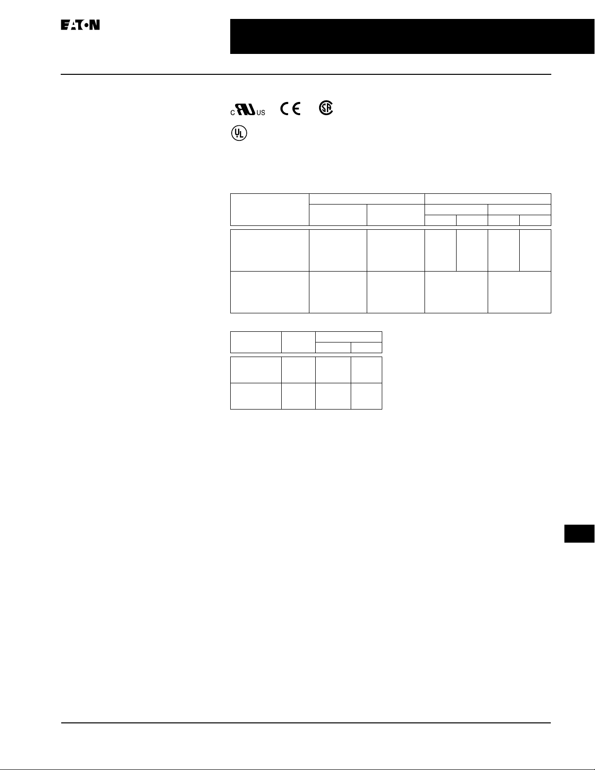
Table 3-30. Coil Resistance for D3PR Series
Coil Voltage Ohms mA
D3PR2/PR3 D3PR5 – DC
6V AC
12V AC
24V AC
120V AC
240V AC
6V DC
12V DC
24V DC
48V DC
110V DC
4.2
18
72
2200
7200
32
120
470
1900
10000
Table 3-31. Coil Resistance for D3PF Series
Coil Voltage Ohms mA
50 Hz 60 Hz
24V AC
120V AC
240V AC
12V DC
24V DC
110V DC
1,700
7,200
120
470
10,000
72
398.0
76.0
28.0
100.0
49.9
13.2
340
65
24
—
—
—
(Each Coil)
—
—
52
1200
3200
—
88
350
—
4000
D3PR2/PR3 – AC D3PR5 – AC
50 Hz 60 Hz 50 Hz 60 Hz
550
275
137
458
229
11 4
28
13
23
11
187
100
50
25
11
—
—
13
3.5
1. 7
—
—
11
2.8
1. 6
—
136
69
—
27
3
Page 2
3-24
Control Relays & Timers
General Purpose Plug-In Relays
D3PR/DP3F Series — Standard and Full Featured
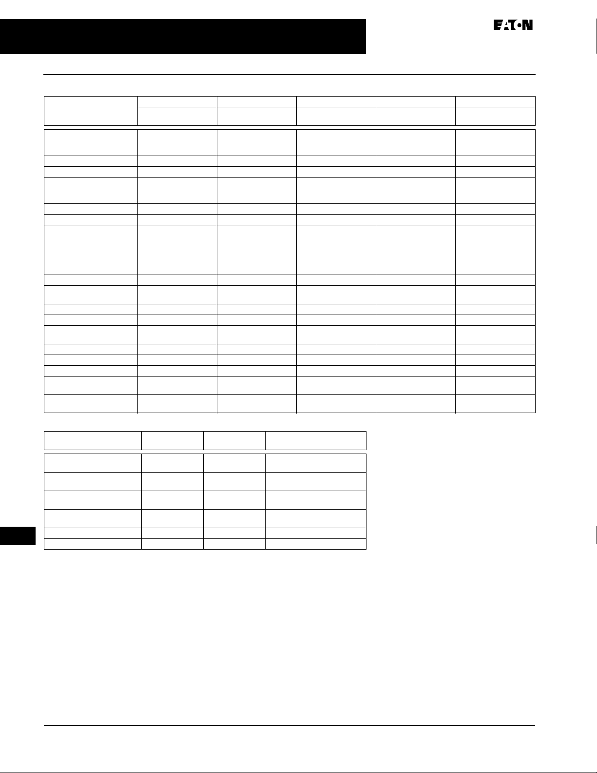
Table 3-32. Relay Specifications
D3PR2/D3PR3 D3PR2/D3PR3 D3PF2/D3PF3 D3PR5 D3PR5
Resistive Load
(p.f. = 1)
Rated Load 240V AC 10A
Carry Current 10A 10A 12 Amps 10A 10A
Max. Operating Voltage 240V AC/DC 240V AC/DC 110% of nominal 240V AC/DC 240V AC/DC
Contact Resistance 50 milli Ω’s Max. @
Dielectric Strength 1500V 1500V 1500V 1500V 1500V
Approx. Weight 3.5 oz (99.2g) 3.5 oz (99.2g) 3.1 oz (88g) 3.5 oz (99.2g) 3.5 oz (99.2g)
Temperature —
Operating
Storage
Contact Material AgCdO (Au Flashed) AgCdO (Au Flashed) AgCdO (Au Flashed) AgCdO (Au Flashed) AgCdO (Au Flashed)
Max. Switching Capacity 2500 VA
Min. Permissible Load 100 mA @ 12V 100 mA @ 12V 100 mA 100 mA @ 12V 100 mA @ 12V
Pickup Voltage (max.) 80% 80% 85% AC; 80% DC — —
Drop Out Voltage (min.) 10% 10% 30% AC
Set/Reset Voltage (max.) — — — 80% 80%
Voltage (max.) 110% 110% 110% 110% 110%
Mechanical Life (min.) 10,000,000 10,000,000 5 million (No Load) 10,000,000 10,000,000
Electrical Life @
All Contact Ratings (min.)
Maximum hp Ratings 1/3 hp (120V AC)
120V AC 12A
28V DC 10A
10 Amps 120V AC or
24V DC
-49 – 131°F
(-45 – 55°C) AC
-49 – 158°F
(-45 – 70°C) DC
-40 – 221°F (-40 – 105°C)
280W
100,000 100,000 200,000 operations at
1/2 hp (240V AC)
Inductive Load
(p.f. = 0.4, L/R = 7 ms)
240V AC 7A
120V AC 7A
28V DC 7A
50 milli Ω’s Max. @
10 Amps 120V AC or
24V DC
-49 – 131°F
(-45 – 55°C) AC
-49 – 158°F
(-45 – 70°C) DC
-40 – 221°F (-40 – 105°C)
1750 VA
196W
1/3 hp (120V AC)
1/2 hp (240V AC)
Resistive Load
(p.f. = 1.0)
240V AC 12A
120V AC 12A
28V DC 12A
50 milli Ω’s Max. @
10 Amps 120V AC or
24V DC
-22 – 122°F (-30 – 50°C)
-22 – 212°F (-30 – 100°C)
12 Amps 1100 VA
10% DC
Rated Res. Load
1/3 hp, 120V AC
1/2 hp, 240V AC
Resistive Load
(p.f. = 1)
240V AC 10A
120V AC 12A
30V DC 10A
50 milli Ω’s Max. @
10 Amps 120V AC or
24V DC
-49 – 131°F
(-45 – 55°C) AC
-49 – 158°F
(-45 – 70°C) DC
-40 – 221°F (-40 – 105°C)
72W
——
100,000 100,000
1/3 hp (120V AC)
1/2 hp (240V AC)
Inductive Load
(p.f. = 0.4, L/R = 7 ms)
240V AC 7A
120V AC 7A
50 milli Ω’s Max. @
10 Amps 120V AC or
24V DC
-49 – 131°F
(-45 – 55°C) AC
-49 – 158°F
(-45 – 70°C) DC
-40 – 221°F (-40 – 105°C)
440 VA
60W
1/3 hp (120V AC)
1/2 hp (240V AC)
April 2009
30V DC 7A
Table 3-33. Socket Specifications
Catalogue
Number
D3PA2 10A, 600V
D3PA3-A2 5A, 600V
D3PA6 5A, 600V
D3PA7 5A, 600V
D3PA4 10A, 260V N/A AWG 14 Max.
3
D3PA5 10A, 260V N/A AWG 14 Max.
Electrical
Ratings
15A, 300V
15A, 300V
16A, 300V
16A, 300V
Mounting
Torque
8 – 10 in-lbs AWG 12 to 22
8 – 10 in-lbs AWG 12 to 22
8 – 10 in-lbs AWG 12 to 20
8 – 10 in-lbs AWG 12 to 20
Hook-Up Wire
Range
Solid or Stranded
Solid or Stranded
Solid or Stranded
Solid or Stranded
Page 3

April 2009
Control Relays & Timers
General Purpose Plug-In Relays
D3PR/DP3F Series — Standard and Full Featured
3-25
Catalogue Number Structure
Table 3-34. D3 Series Catalogue Numbering System
D 3 P R 2 3 A
Family Type
D3PR — Standard Relay
D3PF — Full Featured Relay
Contact Configuration
2 = DPDT (8-Pin)
3 = 3PDT (11-Pin)
5 = DPDT Latching (11 Pin)
Blank = Relay with Test Button
A = LED, Test Button, Flag Indicator, Lock-
Down Door, Finger-Grip Cover, I.D. Tag
For deciphering Catalogue Numbers. Do not use for ordering as not all
combinations are readily available.
D3PR only.
Options
Table 3-35. Relay/Socket Quick Reference
Relay
Type
D3PR2 8 Pin Octal D3PA2
D3PF2 8 Pin Octal D3PA2 PQC-1344
D3PR3 11 Pin Octal D3PA3-A2
D3PF3 11 Pin Octal D3PA3-A2 PQC-1351
D3PR5 11 Pin Octal D3PA3-A2
Socket Type Socket Hold Down
D3PA4
D3PA6
8 Pin Octal —
Finger-safe terminals
11 Pin Octal —
Finger-safe terminals
D3PA6 PQC-1332
D3PA5
D3PA7
D3PA7 PQC-1332
D3PA5
D3PA7
Coil Voltage
A =
120V AC
A1 =
110V DC
B =
240V AC
P =
P1 =
R =
12V AC
R1 =
12V DC
T =
24V AC
T1 =
24V DC
W1 =
48V DC
Spring/Clip
PQC-1344
Not Available
PQC-1332
PQC-1351
Not Available
PQC-1332
PQC-1351
Not Available
PQC-1332
6V AC
6V DC
Product Selection
Table 3-36. D3 Product Selection
Std.
Pack
Standard DPDT with Test Button
Coil Voltage:
12V AC
24V AC
120V AC
240V AC
12V DC
24V DC
110V DC
1
1
1
1
1
1
1
DPDT Full Featured Relay
24V AC
120V AC
240V AC
12V DC
24V DC
110V DC
1
1
1
1
1
1
Standard 3PDT with Test Button
Coil Voltage:
24V AC
120V AC
240V AC
12V DC
24V DC
110V DC
1
1
1
1
1
1
3PDT Full Featured Relay
24V AC
120V AC
240V AC
24V DC
110V DC
DPDT Latching
24V AC
120V AC
1
1
1
1
1
1
1
DIN Rail Sockets
2-Pole (8-Pin)
2-Pole (8-Pin) Finger-Safe
3-Pole (11-Pin)
3-Pole (11-Pin) Finger-Safe
10
1
10
1
Panel Mount Sockets
2-Pole
3-Pole
10
10
Accessories
Hold Down Clip
Hold Down Clip
Hold Down Clip
Hold Down Clip
Coil Buss Jumper for
D3PA6 & D3PA7
DIN Rail End Stop
Additional coil voltages available — consult Contact Customer Support
Centre 1-800-268-3578.
Dimensions on Page 31.
CSA approval is not applicable to D3PR5 Latching Relays.
IP20 Rated.
10
25
10
100
25
100
Catalogue
Number
D3PR2R
D3PR2T
D3PR2A
D3PR2B
D3PR2R1
D3PR2T1
D3PR2A1
D3PF2AT
D3PF2AA
D3PF2AB
D3PF2AR1
D3PF2AT1
D3PF2AA1
D3PR3T
D3PR3A
D3PR3B
D3PR3R1
D3PR3T1
D3PR3A1
D3PF3AT
D3PF3AA
D3PF3AB
D3PF3AT1
D3PF3AA1
D3PR5T
D3PR5A
D3PA2
D3PA6
D3PA3
D3PA7
D3PA4
D3PA5
PQC-1344
PQC-1332
PQC-1351
PWC-1325
D3PJ1
PFP-M
3
Page 4

3-26
Dimensions
Control Relays & Timers
General Purpose Plug-In Relays
April 2009
D3PR/DP3F Series — Standard and Full Featured
6-32 x 0.312 Combination
Head Screw and Pressure Clamping Plate
2.14
(54.3)
2.03
(51.4)
(8 Places)
Two 0.165
(4.2) Dia.
Slots
1.30
(32.9)
1.60
(40.5)
Max.
Tolerances: ± 0.010
± (0.25)
Unless Otherwise Shown
0.97
(24.6)
Max.
0.82 (20.8)
0.58 (14.7)
Figure 3-31. D3PA2 — Approximate Dimensions in Inches (mm)
1.37
(34.8)
Max.
1.37
(34.8)
Max.
8 1
7
2
6
3
45
D3PR2
Terminal Arrangement
(Bottom View)
0.03
(0.8)
2.25
(57.2)
Max.
10
9
8
D3PR3
11 1
2
3
4
567
Figure 3-32. D3PR2/D3PR3 — Approximate Dimensions in Inches (mm)
Terminal Arrangement
218 7
3456
1.37 (34.8)
Max.
1.37
(34.8)
Max.
RESET
(–)
(+)
6
7
5
4 8
3
(–)
210
111
9
(+)
COM
OPERATE
DC Operated AC Operated
Single Wound AC Coil
Recommended diodes used in
AC versions 1N4007 or equivalent.
2.33 (59.2)
Max.
RESET
6
7
5
4 8
3
9
210
111
OPERATE
Figure 3-33. D3PR5 — Approximate Dimensions in Inches (mm)
6-32 x 0.312 Combination
3
Head Screw and Pressure Clamp
2.05
(52.07)
Max.
(11 Places)
2.06
(52.3)
2.33 (59.1)
Max.
0.125 – 0.156
(3.17 – 3.96))
Tolerances: ± 0.010
± (0.25)
Unless Otherwise Shown
Two 0.17
(4.3) Dia.
Holes
0.97
(24.6)
Figure 3-34. D3PA3-A2 — Approximate Dimensions in Inches (mm)
0.15 (3.6)
0.58 (14.7)
0.77 (19.6)
Terminal Arrangement
2 1 11 10
3
9
4
8765
Page 5

April 2009
D3PJ1
Break-Away
Terminals
0.09
(2.3)
0.10
(2.5)
Max.
Control Relays & Timers
General Purpose Plug-In Relays
D3PR/DP3F Series — Standard and Full Featured
10 2
INPUT INPUT
A1
A2
1
11
2
10
3
9
4
8
39
5
7
6
NEMA:
0.13 (3.3)
Max.
(16.2)
0.64
14
11
1.44
(36.6)
Figure 3-38. D3PA7 — Approximate Dimensions in Inches (mm)
IEC:
6211
54
34
11
31
8 7
32 24 22 12
(38.1)
1.50
3.01
(76.5)
3-27
Bottom View
1.26 (32.0)
1.40 (35.6)
0.02
(0.6)
0.32
(8.1)
Figure 3-35. D3PJ1 — Approximate Dimensions in Inches (mm)
1.55
(39.4)
0.33
(8.4)
2.20
(55)
2.00
(50.8)
2.14
(54.4)
1.00
(25.4)
90°
20°
0.15
(3.8)
0.14 (3.5)
Max.
Figure 3-36. PQC-1332 — Approximate Dimensions in Inches (mm)
2
7
INPUT
INPUT
A2
A1
NEMA:
IEC:
8
1
2
1.44
(36.6)
7
3
6
54
8
6
3
14
24
21
4
5
1
12
22
11
1.41
(35.8)
3.01
(76.5)
Bottom View
0.79
(20.1) Max.
D3
PL
2 – 0.08 (2.0) Dia. Holes
0.15 (3.8)
Bottom View
1.99
1.57
(50.5)
(39.9)
Max.
2 – 0.14 (3.6) Dia. Mounting
Holes or 2 – M3 Mounting
Screw Holes
1.57
1.22
(31.0)
Dia. Holes
Mounting Holes
(39.9)
1.32
(33.5) Max.
2.26
(57.4)
(30.0)
0.14
(3.6)
1.18
Dia.
Figure 3-39. D3PA4 — Approximate Dimensions in Inches (mm)
2 – 0.08 (2.0) Dia. Holes
2.01
(51.1)
Max.
1.57
(39.9)
1.18
(30.0)
Dia.
0.15 (3.8)
0.24 (6.1)
0.04 (1.01)
Bottom View
2 – 0.14 (3.6) Dia. Mounting
Holes or 2 – M3 Mounting
Screw Holes
1.57
1.22
(31.0)
Dia. Holes
Mounting Holes
(39.9)
0.14 (3.6)
1.38
(35.1) Max.
2.26
(57.4)
0.83 (21.1) Max
D3
PL
Figure 3-40. D3PA5 — Approximate Dimensions in Inches (mm)
3
Figure 3-37. D3PA6 — Approximate Dimensions in Inches (mm)
Page 6

3-28
0
)
.
.
)
6
3
5
8
5
8
6
3
0
)
.
)
.
)
5
8
9
0
6
3
0
8
9
5
6
3
Control Relays & Timers
General Purpose Plug-In Relays
April 2009
D3PR/DP3F Series — Standard and Full Featured
Schematic Diagram
1.32 (33.5)
Max.
Plastic
ID Tag
(34.3)
Max.
1.35
1.38 (34.9)
Max
1.4
(35.6
Max
Terminal Arrangement (Bottom View
2.25 (57.2) Max.
2.28 (57.9) Max.
0.54
(13.7)
Max.
Schematic Diagram
1.32 (33.5)
Max.
Plastic
ID Tag
(34.3)
Max.
Terminal Arrangement (Bottom View
1.35
1.38 (35.1
Max
1
2.25 (57.2) Max.
2.28 (57.9) Max.
(35.6
Figure 3-41. D3PF2 — Approximate Dimensions in Inches (mm) Figure 3-42. D3PF3 — Approximate Dimensions in Inches (mm)
1.4
Max
0.54
(13.7)
Max.
3
 Loading...