

Page 1
Effective February 2015
Instruction Leaflet IL 29C104E
Supersedes IL 29C104D Dated 02/12
Installation Instruc tions for DK, KDB, KD, HKD, KDC, KW, HKW,
KWC, CKD, CHKD Circuit Breakers and Molded Case Switches
Contents
Introduction . . . .. . . . .. . . .. . . .. . . . . . .. . . .. . . . .2
Installation . . . . .. . . . .. . . .. . . .. . . .. . . . . . .. . . . 3
Replacement of Existing Eaton Circuit Breakers
Types DA, JA, KA, HKA, LB, LBB, HLB . . 6
Manual Operation and Thermal Magnetic Trip
Unit Adjustment . . . . . .. . . . . . . . . .. .7
Inspection and Field Testing .. . . .. . . .. . . .. . . .. 8
Page noitpircseD
Page 2
Effective February 2015
Installation Instructions for DK, KDB, KD, HKD, KDC, KW, HKW,
KWC, CKD, CHKD Circuit Breakers and Molded Case Switches
WARNING
DO NOT ATTEMPT TO INSTALL OR PERFORM
MAINTENANCE ON EQUIPMENT WHILE IT IS ENERGIZED. DEATH, SEVERE PERSONAL INJURY, OR
SUBSTANTIAL PROPERTY DAMAGE CAN RESULT
FROM CONTACT WITH ENERGIZED EQUIPMENT.
ALWAYS VERIFY THAT NO VOLTAGE IS PRESENT
BEFORE PROCEEDING WITH THE TASK, AND
ALWAYS FOLLOW GENERALLY ACCEPTED SAFETY PROCEDURES.
EATON IS NOT LIABLE FOR THE MISAPPLICATION
OR MISINSTALLATION OF ITS PRODUCTS.
The user is cautioned to observe all recommendations,
warnings, and cautions relating to the safety of personnel and equipment as well as all general and local
health and safety laws, codes, and procedures.
The recommendations and information contained herein
are based on Eaton experience and judgment, but
should not be considered to be all-inclusive or covering
every application or circumstance which may arise. If
any questions arise, contact Eaton for further informa-
tion or instructions.
1. INTRODUCTION
General Information
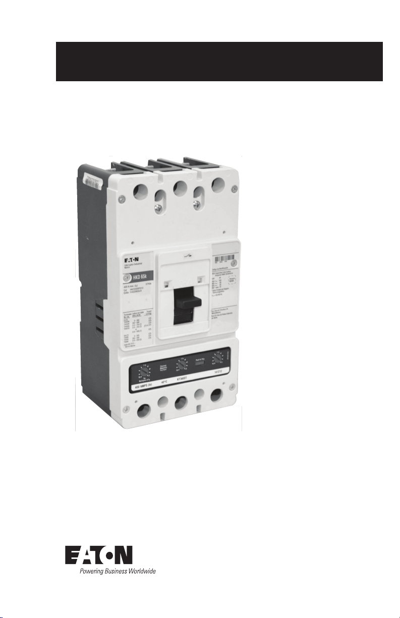
The K-frame Series C circuit breaker (Figure 1-1) types
KD, HKD, and KDC are 600 Vac maximum rated
devices with interchangeable thermal-magnetic or electronic (Seltronic) trip units rated 400A maximum continuous current. Circuit breaker types KW, HKW, and KWC
are 660 Vac maximum rated devices using interchangeable adjustable thermal/adjustable magnetic or electronic trip units rated up to 400A continu
type KDB noninterchangeable trip circuit breaker is rated
600 Vac maximum with a maximum continuous current
rating of 400A. The type DK 240 Vac maximum circuit
breaker is also a noninterchangeable trip device with trip
unit ratings from 250A to 400A. Refer to Table 4-1 on
page 9 for all av
breakers are listed in accordance with Underwriters
Laboratories, Inc. Standard UL489 and satisfy the (P1)
requirements of the International Electrotechnical
Commission Recommendations No. IEC 157-1. Model
W circuit breakers satisfy the requirements of IEC C947-
2. Molded case switches are listed in accordance with
UL 489.
ailable trip unit ratings. Model D circuit
o
us current. The
100 Percent Rated K-Frame Circuit Breakers
CKD and CHKD circuit breakers are suitable for continuous operation at 100 percent of the frame rating if
used with an 90°C insulated wire and AL9CU terminals
in an enclosure which measures at least 24” high x 15”
wide x 6” deep. Ventilation is not required in an enclosure having these minimum dimensions. CKD and
CHKD 100 percent rated circuit breakers use electronic
trip units only.
Figure 1-1 K-Frame Model D Series C Circuit Breaker
Frame with KT Trip Unit Installed
2
EATON CORPORATION
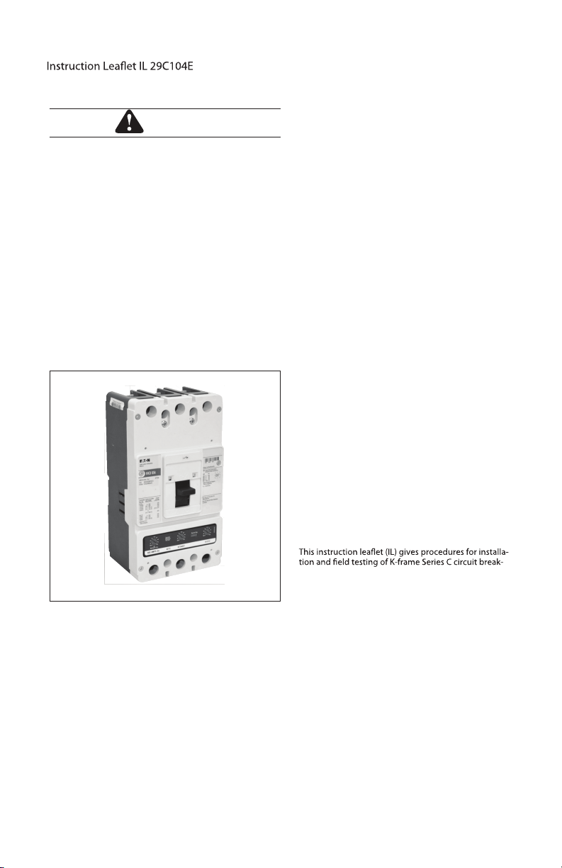
ers. Instructions are also provided for replacement of
existing Eaton circuit breaker types DA, LB, LBB, HLB,
JA, KA, and HKA. For this publication, the term circuit
breaker shall also include the molded case switch.
Page 3
Installation Instructions for DK, KDB, KD, HKD, KDC, KW, HKW,
KWC, CKD, CHKD Circuit Breaker and Molded Case Switches
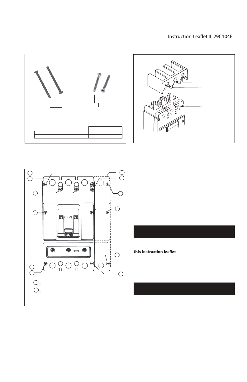
Pan Head Screws
3 - Pole 4 - Pole
No. 8 x 1.63 in, Flat - Head 6 3
.190 - 32 x 3.125 in, Pan - Head 2 7
Flat Head, Thread
Forming Screws
Figure 2-1 Cover Mounting Hardware
Terminal Cover
e installation procedure consists of
Figure 2-3 Terminal Cover Installation
,
Effective February 2015
Dovetails
Mounting
Slots
1
3P
4P
2
2
1
3
1
3P
2
4P
Screw, No. 8x 1.63 Inch, Flat Head, Cross-Recessed,
1
Thread Forming.
Screw .190-32 x 3.125 Inch Pan Head, Cross-Recessed.
2
Note: Hatched lines show additional pole and screw for
4-pole circuit breaker.
Figure 2-2 Cover Screw Installation Positions
2. INSTALLATION
1
3P
2
The installation procedure consist of inspecting the cir-
4P
cuit breaker and, as applicable, installing the trip unit and
rating plug, accessories, interphase barriers, and terminals; mounting the circuit breaker; connecting the line
2
and load conductors; torquing terminals; and attaching
terminal shields. Circuit breaker frames, trip units, rating
plugs, accesories, mounting hardware, and unmounted
1
terminals may be supplied in separate packages. To
install the circuit breaker, perform the following steps.
NOTICE
If circuit breaker is replacing a DA, JA, KA, HKA, LB,
LBB, or HLB circuit breaker, refer to section 3 of
2
DK and KDB circuit breakers are factory sealed for
reverse feed applications under UL489. UL requires
that internal accessories be installed at the factory
in these types of circuit breakers.
1
3P
NOTICE
If required, internal accessory installation in any
type of circuit breaker should be done before the
EATONON CORPORATION
3
Page 4

Instruction Leaft IL 29C104E
Effective February 2015
circuit breaker is mounted and connected. Refer to
2-1. Make sure that the circuit breaker is suitable for the
intended installation by comparing nameplate data with
existing equipment ratings and system requirements.
Inspect the circuit breaker for completeness, and check
for damage before mounting. Uninstalled cover mounting hardware is supplied in a plastic bag with the circuit
breaker frame. (See Figure 2-1.)
2-2. Remove installed cover screws and cover.
Installation Instructions for DK, KDB, KD, HKD, KDC, KW,
KWC, CKD, CHKD Circuit Breakers and Molded Case Switches
TA300K / TA350K
T300K / T350K Terminals
Circuit Breaker
Terminal Conductors
NOTICE
The circuit breaker handle must be in the tripped or
OFF position to remove the cover. Instructions for
installing the trip unit and accessories are supplied
with the devices.
2-3. If not already installed, mount trip unit and accessories (if required) in circuit breaker frame. Rating plug
must be installed in Seltronic trip units.
CAUTION
WHEN REMOVED AND REINSTALLED, THREADFORMING SCREWS WILL TRY TO REFORM THE
THREADS IN THE BASE. CARE SHOULD BE TAKEN
EVERY TIME A THREAD-FORMING SCREW IS USED
TO ENSURE THE SCREW STARTS IN THE ORIGINAL
THREADS. DAMAGED THREADS CAN RESULT IN
IMPROPER CIRCUIT BREAKER COVER RETENTION.
2-4. Replace cover and install pan-head screws followed by thread-forming screws as shown in Figure 2-2.
Torque cover screws to 18-23 lb-in (2-2.6 N.m.).
2-5. If not already installed, mount terminals as shown
in Figure 2-4. Secure the terminals to the circuit breaker
using a 7/32-inch socket wrench, and torque to 6-8 lb-ft
(8-11 N.m). After mounting the circuit breaker and
before installation of the conductors, the terminal mounting screw can be checked or retightened through the
terminal when the conductor screw is removed. If
Warning label is supplied with terminal, place on upper
portion of circuit breaker cover.
WARNING
THE VOLTAGE IN ENERGIZED EQUIPMENT CAN
Conductor
Screws
Terminal Mounting Screw
Terminal
Mounting
Screw
TA400K, TA401K, TA402K,
T400K Terminals
Figure 2-4 Terminal Installation
CAUSE DEATH OR SEVERE PERSONAL INJURY.
BEFORE MOUNTING THE CIRCUIT BREAKER IN AN
ELECTRICAL SYSTEM, MAKE SURE THERE IS NO
VOLTAGE PRESENT WHERE WORK IS TO BE PERFORMED. SPECIAL ATTENTION SHOULD BE PAID
TO REVERSE FEED APPLICATIONS TO ENSURE
NO VOLTAGE IS PRESENT.
NOTICE
Depending on the equipment configuration, the circuit breaker can be mounted using different styles
of hardware. The following steps describe how to
mount the circuit breaker using standard hardware.
When special hardware is needed (for example, with
the electrical operator), the instruction leaflet
describing the accessory also describes the special
mounting arrangements.
2-6. To mount the circuit breaker, perform the following
steps:
a. For individual surface mounting, drill mounting panel
using the drilling plan shown in Figure 2-5. For panelboard mounting, only load end support mounting
4
EATON CORPORATION
Page 5

Installation Instructions for DK, KDB, KD, HKD, KDC, KW HKW,,
KWC, CKD, CHKD Circuit Breakers and Molded Case Switchese
Effective February 2015
C
Circuit
L
Breaker
Handle
1.719
(43.66)
.250-20 (M6-1.0) TAP
- 6 Holes
4 Pole Breaker
(21.44)
1.719
(43.66)
.844
4.922
(125.01)
(214.32)
3.516
(89.31)
8.438
2, 3 Pole Breaker
CLCircuit Breaker Handle
1.719
(43.66)
.250-20 (M6-1.0) TAP
- 4 Holes
.859
(21.82)
Figure 2-5 Circuit Breaker Mounting Bolt Drilling Plans
holes are required. For deadfront cover applications,
cut out cover to correct escutcheon dimensions, see
Figure 2-6.
b. If circuit breaker includes factory or field installed
internal accessories, make sure accessory wiring can
be reached when the circuit breaker is mounted.
c
. Position circuit breaker on mounting surface.
NOTICE
Labels with accesory connection schematic diagrams are provided on the side of the circuit breaker.
A note should be made of the diagrams if the labels
cannot be seen when the circuit breaker is mounted.
.d. Install circuit breaker mounting screws, washers, and
nuts. Tighten screws firmly, but do not exceed 28
pounds-inches (3 N.m.).
CAUTION
WHEN ALUMINUM CONDUCTORS ARE USED, THE
APPLICATION OF A SUITABLE JOINT COMPOUND
IS RECOMMENDED TO REDUCE THE POSSIBILITY
Circuit Breaker HandleC
L
.344R
(8.74)
Circuit Breaker HandleC
L
1.88R
(4.77)
Trip Unit
Access Area
2.625
(66.67)
Figure 2-6 Circuit Breaker Escutcheon Dimensions for
3- and 4-Pole Circuit Breakers
OF TERMINAL OVERHEATING. OVERHEATING CAN
CAUSE NUISANCE TRIPPING AND DAMAGE TO
THE CIRCUIT BREAKER.
4.782
(121.46)
.921
(23.39)
3.750
(95.25)
1.313
(33.35)
1.640
(41.66)
1.250
(31.75)
(60.73)
2.391
NOTICE
When a dual conductor terminal (Catalog No.
TA401K, TA400K, or T400K) is installed on the circuit breaker and a single conductor is used, the
conductor should be installed in the terminal opening nearest to the circuit breaker terminal mounting
conductor.
2-7. Connect line and load conductors and accessory
leads.
2-8. When step-type terminals (Cat. No. TA400K,
TA401K, TA402K, and T400K) are used, terminal
shields (supplied with the terminals) must be installed
on the circuit breaker (Figure 2-3). Warning label supplied with the kit must be attached to the circuit breaker
front cover.
2-9. If required, install terminal shield on circuit breaker
cover with mounting screws provided.
2-10. After the circuit breaker is installed, check all
mounting hardware and terminal connecting hardware
for correct torque loading. Torque values for line/load
EATON CORPORATION
5
Page 6

Effective February 2015
Installation Instructions for DK, KDB, KD, HKD, KDC, KW, HKW
KWC, CKD, CHKD Circuit Breakers and Molded Case Switchese
Table 2-1 Terminal Types
Terminal Terminal Screw AWG
Cat. No. Material Head Wire Wire Type Value
Body Type Range Range lb-in
TA300K Aluminum Socket 3-350(1) 35-185
TA350K Aluminum Socket 250-500(1) 120-240 Cu/Al 375 (42)
TA400K Aluminum Socket 3/0-250(2) 95-120(2) Cu/Al 275 (31)
TA401K Aluminum Socket 250(2) 120(2) Cu/Al 275 & 375
TA402K Aluminum Socket 500-750(1) 240-300 Cu/Al 550 (62)
T300K Copper Socket 3-350(1) 35-185 Cu Only 275 (31)
T350K Copper Socket 250-500(1) 120-240 Cu Only 375 (42)
T400K Copper Socket 3/0-250(2) 95-120(2)Cu Only 275 (31)
terminals are given in Table 2-1 and on the circuit
breaker nameplate.
3. REPLACEMENT OF EXISTING EATON CIRCUIT
BREAKERS TYPES DA, JA, KA, HKA, LB, LBB,
AND HLB
Although the physical size of the K-frame Series C circuit breakers is the same as the DA, JA, KA, HKA, LB,
LBB, and HLB family, there are certain differences that
must be considered when making replacements.
Circuit breaker mounting details, panel cutouts, and
terminal centerline locations are identical.
Handle locations, handle throw, and terminal connec-
tion details are different. Therefore, existing handle
mechanisms and externally-mounted accessories,
including electrical operator, key interlocks, etc., must
be replaced or mounting detail modified. Consult
Eaton for additional information.
Metric
Wire Torque
(N.m.)
Cu/Al
275 (31)
or or (31 &42)
500(1) 240(1) Cu/Al 375 (42)
WARNING
DO NOT ATTEMPT TO INSTALL OR PERFORM
MAINTENANCE ON EQUIPMENT WHILE IT IS ENERGIZED. DEATH, SEVERE PERSONAL INJURY, OR
SUBSTANTIAL PROPERTY DAMAGE CAN RESULT
FROM CONTACT WITH ENERGIZED EQUIPMENT.
ALWAYS VERIFY THAT NO VOLTAGE IS PRESENT
BEFORE PROCEEDING WITH THE TASK, AND
ALWAYS FOLLOW GENERALLY ACCEPTED SAFETY PROCEDURES.
NOTICE
When replacing an existing circuit breaker of the
types listed above, make sure the voltage, continuous current, and interrupting rating of the new circuit breaker is suitable.
3-1. If existing circuit breaker is equipped with a handle
mechanism, remove the mechanism. Contact Eaton
Customer Service for ordering information on new
handle mechanisms.
3-2. Disconnect accessory electrical leads and main
conductors.
3-3. Remove all external accessories that would
impede removal of the circuit breaker.
3-4. Remove circuit breaker from installation.
3-5. Install K-Frame Series C circuit breaker that has
been prepared using steps 2-1 through 2-3 to fit installation requirements given below.
Panelboard Installation
Two types of panelboard construction/circuit breaker
mounting arrangements are covered in the following
procedures: convertible distribution panels (CDP),
where the circuit breakers are mounted in a dual horizontal arrangement; and other panelboard constructions, where the existing circuit breaker is used as a
main disconnect and mounted vertically.
CAUTION
TO AVOID OVERHEATING, DO NOT INSTALL KFRAME SERIES C CIRCUIT BREAKERS WITH TRIP
UNITS RATED ABOVE 225A ON EXISTING 225A JA,
KA, OR HKA PANELBOARD CONNECTING STRAPS.
NOTICE
When existing CDP panel board connecting straps
are retained, a supplementary adapter and clip
(Catalog No. TAD3) must be used to compensate for
the change in height of the new circuit breaker terminal connections. The adapter may be used on either
6
EATON CORPORATION
Page 7

Installation Instructions for DK, KDB, KD, HKD, KDC, KW, HKW,
KWC, CKD, CHKD Circuit Breakers and Molded Cases Switches
Effective February 2015
side of the circuit breaker terminal mounting conductor permitting continued use of top or bottom
mounted connecting straps. If series C panelboard
connecting straps that mount from the rear of the
circuit breaker are used, the adapter is not required.
3-6. When required, position the TAD3 adapter under
those circuit breaker terminal connectors that will be
bolted to the panelboard connecting straps. Secure
adapters with the spring clips supplied. Refer to instructions supplied with adapter.
3-7. Position circuit breaker in correct location on panelboard chassis.
3-8. Install socket-head bolts through circuit breaker
terminal connectors and screw into panelboard connecting straps. Torque to 120 pound-inches (16.9 N.m).
3-9. Install circuit breaker mounting screws, washers,
and nuts in load end of circuit breaker. Tighten screws
3-10. After mounting the circuit breaker, refer to section
2 for instructions how to connect main conductors and
accessory leads, as required.
Individually Mounted Devices
With the change in height of the circuit breaker terminal
connector, K-frame Series C circuit breakers can be
used to replace individually mounted existing types DA,
JA, KA, HKA, LB, LBB, and HLB circuit breakers only
when the following conditions are considered:
Fixed Rear Connecting Studs
Contact Eaton Customer Service for ordering information.
Plug-In Support Blocks
New male plug-in adapters will be required. Existing stationary support block receptacles can be used with new
Series C male plug-in adapters. Contact Eaton Customer Service for ordering information.
Front or Rear Connected Bus Bars
Use existing connecting details coupled with K-Frame
terminal adapter kit (Catalog No. TAD3).
4. MANUAL OPERATION, AND THERMALMAGNETIC TRIP UNIT ADJUSTMENT
Manual Operation
Manual operation of the circuit breaker is controlled by
the circuit breaker handle and the PUSH-TO-TRIP but-
ton in the trip unit. The circuit breaker handle has three
positions, two of which are shown on the cover with
raised lettering to indicate ON and OFF. On the sliding
handle barrier, ON, OFF, and trip are also shown by a
color-coded strip for each circuit breaker handle position: red for ON, white for tripped, and green for OFF.
(See Figure 4-1.)
Circuit Breaker Reset
After an automatic or accessory initiated trip, or a manual PUSH-TO-TRIP operation, the circuit breaker is reset
by moving the circuit breaker handle to the extreme
OFF position.
NOTICE
In the event of a thermal trip in a thermal magnetic
type trip unit, the circuit breaker cannot be reset
until the thermal element in the trip unit cools. A circuit breaker with an electronic type trip unit can be
reset immediately.
No circuit breaker should be reclosed until the cause of
Handle Postition Indicator
Color: Red - On
White - Trip
On
Trip
(Reset)
International
Symbols
On
Thermal-Magnetic
Trip Unit Adjustment
Button (3 Places)
Figure 4-1 Circuit Breaker Manual Controls
On/
Push-to-Trip
Button
EATON CORPORATION
7
Page 8

Effective February 2015
Installation Instructions for DK, KDB, KD, HKD, KDC, KW, HKW,
KWC, CKD, CHKD Circuit Breakers and Molded Case Switches
PUSH-TO-TRIP Button
The PUSH-TO-TRIP button checks the circuit breaker
tripping function and is used to periodically exercise the
operating mechanism in thermal-magnetic trip units. The
button is designed to be operated by a small screwdriver.
The rating plug in Electronic trip Units is the PUSH-TOTRIP button and is operated by finger pressure. There is
no PUSH-TO-TRIP button in the molded case switch.
Thermal-Magnetic Trip Unit Adjustment
The magnetic element of each pole of the trip unit can
be adjusted by rotating the adjustment buttons on the
front face of the trip unit with a screwdriver. The buttons
have several settings as indicated on the nameplate
with values in multiples of the trip unit ampere rating (I
as shown in Figure 4-2. To adjust the setting, rotate
each button clockwise until arrow button points to
desired setting.
)
h
t
Interchangeable Trip Units
For additional information on thermal-magnetic trip
units, refer to I.L. 29C603, and for electronic (Seltronic)
trip units, refer to I.L. 29C604. (IL supplied with trip unit.)
5. INSPECTION AND FIELD TESTING
Series C molded case circuit breakers are designed to
provide years of almost maintenance-free operation.
The following procedure describes how to inspect and
test a circuit breaker in service.
Inspection and Field Testing
Circuit breakers in service should be inspected periodically. The inspection should include the following checks
5-1 through 5-8.
Adjustment Buttons
Thermal
Magnetic
Trip Unit
7.5
10 5
7.5
Push-to-Trip
10 5
Amps
C
Cat
(I
)
No.
th
7.5
10 5
Magnetic (Im)
Multiples Of I
th
Figure 4-2 Trip Unit Magnetic Adjustment Buttons
WARNING
THE VOLTAGES IN ENERGIZED EQUIPMENT CAN
CAUSE DEATH OR SEVERE PERSONAL INJURY.
BEFORE INSPECTING THE CIRCUIT BREAKER IN
AN ELECTRICAL SYSTEM, MAKE SURE THERE IS
NO VOLTAGE PRESENT WHERE WORK IS TO BE
PERFORMED. SPECIAL ATTENTION SHOULD BE
PAID TO REVERSE FEED APPLICATIONS TO
ENSURE NO VOLTAGE IS PRESENT.
CAUTION
SOME COMMERCIAL CLEANING AGENTS WILL
DAMAGE THE NAMEPLATES OR MOLDED PARTS.
MAKE SURE THAT CLEANING AGENTS OR SOLVENTS USED TO CLEAN THE CIRCUIT BREAKER
ARE SUITABLE FOR THE JOB.
5-1. Remove dust, dirt, soot, grease, or moisture from
the surface of the circuit breaker using a lint-free dry
cloth, brush, or vacuum cleaner. Do not blow debris into
circuit breaker. If contamination is found, look for the
source and eliminate the problem.
5-2. Switch circuit breaker to ON and OFF several
times to be sure that the mechanical linkages are free
and do not bind. If mechanical linkages are not free,
replace circuit breaker.
NOTICE
On molded case switches, there is no PUSH-TO
TRIP feature. Omit step 5-3 when inspecting a
molded case switch and proceed with step 5-4.
5-3. With the circuit breaker in the ON position, press
the PUSH-TO-TRIP button to mechanically trip the circuit breaker. Trip, reset, and switch circuit breaker ON
several times. If mechanism does not reset each time
the circuit breaker is tripped, replace the circuit breaker.
5-4. Check base, cover, and operating handle for
cracks, chipping, and discoloration. Circuit breakers
should be replaced if cracks or severe discoloration is
found.
5-5. Check terminals and connectors for looseness or
signs of overheating. Overheating will show as discoloration, melting, or blistering of conductor insulation, or
8
EATON CORPORATION
Page 9

Installation Instructions for DK, KDB, KD, HKD, KDC, KW, HKW,
KWC, CKD, CHKD Circuit Breakers and Molded Case Switches
Effective February 2015
as pitting or melting of conductor surfaces due to arcing.
If there is no evidence of overheating or looseness, do
not disturb or tighten the connections. If there is evidence of overheating, terminations should be cleaned or
replaced. Before re-energizing the circuit breaker, all
terminations and cable should be refurbished to the condition when originally installed.
5-6. Check circuit breaker mounting hardware, and
tighten if necessary.
hazards. Exposure to certain types of chemicals can
cause deterioration of electrical connections.
5-8. The operation of circuit breakers with Seltronic trip
test kit.
Field Testing
applicable NEMA Standard.
5-7. Check area where circuit breaker is installed for
Table 4-1 Available Trip Unit Ratings
Trip Unit Types
Circuit Fixed Adjustable Adjustable Fixed Adjustable Adjustable
Breaker
KWC
Not available with types DK or KDB
Not UL listed
For adjustable thermal trip units, the magnetic setting is a multiple of the maximum thermal setting. For Seltronic trip units, the
instantaneous/short time setting is a multiple of the rating plug rating.
Thermal-Magnetic Amperes I
Thermal Thermal
300
350
400
100
250 250-315
300 313-400
350
400
th
Magnetic Rating
of I
th
01 ot 5052KD
Electronic (Seltronic
003571
053002-061002,WKH ,WK
004052-002522
Rating
) Amperes I
004-052522521CDK ,DKH
004-513052051
th
Instantaneous/
Short-timegulPgulPMultiplessepyT
Multiples
of I
th
8 ot 2004-002002 ,DK ,BDK
EATON CORPORATION
www.eaton.com
9
Page 10

Instruction leaflet IL 29C104E
Effective February 2015
The instructions for installation, testing, maintenance, or repair
herein are provided for the use of the product in general commercial
applications and may not be appropriate for use in nuclear applications. Additional instructions may be available upon specific request
to replace, amend, or supplement these instructions to qualify them
for use with the product in safety-related applications in a nuclear
facility.
The information, recommendations,descriptions,and safety notations in this document are based on Eaton’s experience and judgment with respect to Retrofitting of Power Breakers. This instruction-
al literature is published solely for information purposes and should
not be considered all-inclusive. If further information is required, you
should consult an authorized
The sale of the product shown in this literature is subject to the
terms and conditions outlined in appropriate Eaton selling policies
or other contractual agreement between the parties. This literature
is not intended to and does not enlarge or add to any such contract.
The sole source governing the rights and remedies of any purchaser
of this equipment is the contract between the purchaser and Eaton.
NO WARRANTIES, EXPRESSED OR IMPLIED, INCLUDING
WARRANTIES OF FITNESS FOR A PARTICULAR PURPOSE OR
MERCHANTABILITY, OR WARRANTIES ARISING FROM COURSE
OF DEALING OR USAGE OF TRADE, ARE MADE REGARDING
THE INFORMATION, RECOMMENDATIONS, AND DESCRIPTIONS
CONTAINED HEREIN,
purchaser or user in contract, in tort (including negligence), strict
liability or otherwise for any special, indirect, incidental or consequential damage or loss whatsoever,including but not limited to
damage or loss of use of equipment, plant or power system, cost
of capital, loss of power, additional expenses
power facilities, or claims against the purchaser or user by its customers resulting from the use of the information, recommendations
and description contained herein.
Eaton
sales represent
In no event will Eaton be responsible to the
ative.
in the use of existing
Installation Instructions for DK, KDB, KD, HKD, KDC, KW, HKW,
KWC, CKD, CHKD Circuit Breakers and Molded Case Switches
© 2013 Eaton Corporation
All Rights Reserved
Printed in Dominican Republic
Publication No. IL 29C104E / TBG000518
Part No. 6632C41H06
February 2015
 Loading...