

Page 1
V7-T3-162 Volume 7—Logic Control, Operator Interface and Connectivity Solutions CA08100008E—February 2014
3
3
3
3
3
3
3
3
3
3
3
3
3
3
3
3
3
3
3
3
3
3
3
3
3
3
3
3
3
3
3.7
Control Relays and Timers
Machine Tool Relays
D26 Series—Type M, 600 Vac Multipole with Convertible Contacts
Contents
Description Page
D15 Series—Freedom 600V Multipole. . . . . . . . . . V7-T3-146
BF/BFD Series—Fixed Contact Industrial
Control. . . . . . . . . . . . . . . . . . . . . . . . . . . . . . . . . V7-T3-151
AR/ARD Series—Convertible Contact
Industrial Control . . . . . . . . . . . . . . . . . . . . . . . . . V7-T3-157
D26 Series—Type M, 600 Vac Multipole
with Convertible Contacts
Product Selection . . . . . . . . . . . . . . . . . . . . . . . V7-T3-163
Technical Data and Specifications . . . . . . . . . . V7-T3-165
Dimensions . . . . . . . . . . . . . . . . . . . . . . . . . . . V7-T3-166
D26 Series—Type M, DC Multipole
with Convertible Contacts . . . . . . . . . . . . . . . . . V7-T3-167
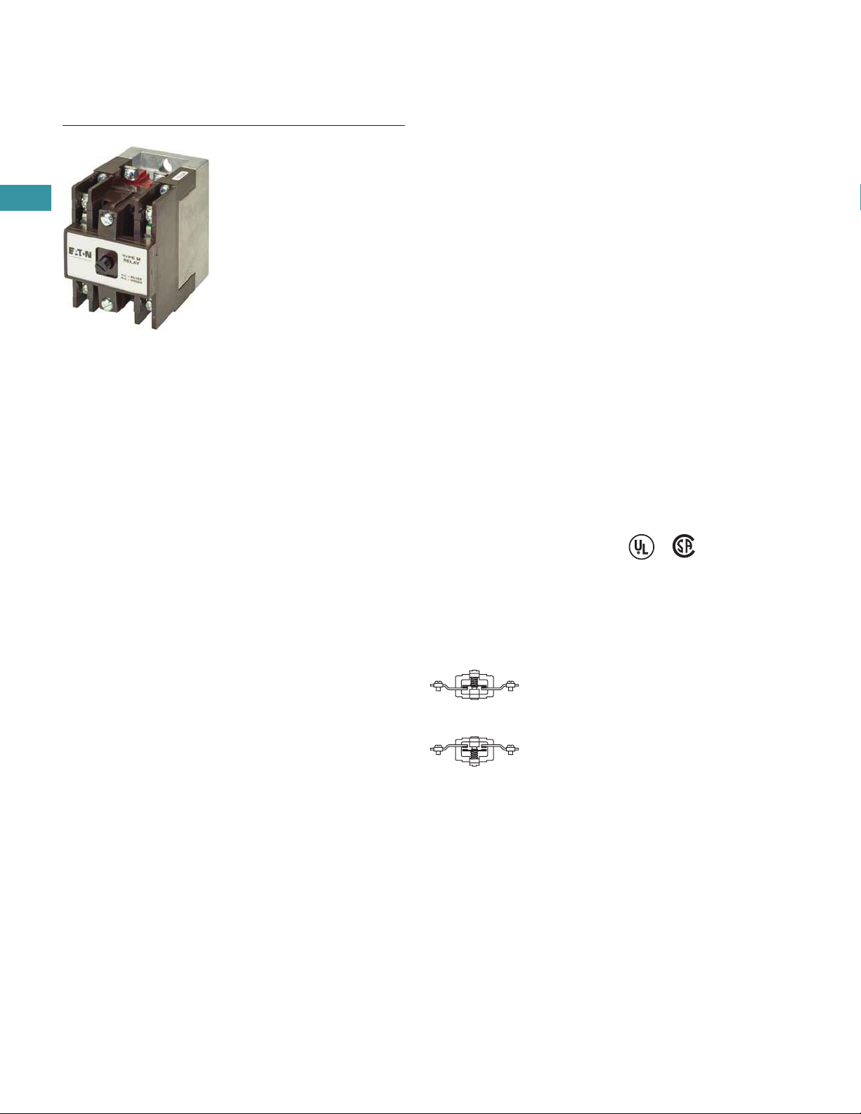
D26 Series—Type M, 600 Vac Multipole with Convertible Contacts
Product Description
Relays can be ordered as
complete devices in any pole
combination up to a
maximum of 12NO or 8NC
and 4NO poles, or can be
assembled from components
shown on Page V7-T3-164.
Relay base assembly
(D26MB) will accept from 1
to 4 rear poles (D26MPR,
D26MPS and/or D26MPL).
Features
Contact poles D26MPR and
D26MPF in 2- through 8-pole
relays are convertible NO to
NC or vice versa. Simply
reverse the terminal screws
and rotate the unit pole 180°
(in either direction).
Options
Adding a front deck, the total
number of poles can be
increased to 8, all convertible
NO to NC.
Adding a D26MF, 4-pole fixed
NO attachment, builds a 12pole relay with 8 convertible
poles and 4 fixed NO poles.
Relays with mechanical latch
are available in any
convertible pole combination
up to eight poles maximum.
To obtain overlapping
contacts, use D26MPS (NO
early closing) and D26MPL
(NC late opening) rear poles,
in related circuits.
Standards and Certifications
●
UL listed—Class No.
NKCR2, File E1230(N)
●
CSA certified—File LR353
Normally Closed
Contact
Normally Open
Contact
Page 2
Volume 7—Logic Control, Operator Interface and Connectivity Solutions CA08100008E—February 2014 V7-T3-163
3
3
3
3
3
3
3
3
3
3
3
3
3
3
3
3
3
3
3
3
3
3
3
3
3
3
3
3
3
3
3.7
Control Relays and Timers
Machine Tool Relays
Product Selection
Complete AC Relays
When Ordering, Specify
●
Catalog number and magnet coil suffix letter.
●
Example: For a 4-pole relay having 4NO contacts, order Catalog Number D26MR40, with a 120V,
60 Hz coil, order D26MR40A.
●
For fast delivery and minimum inventory, it is recommended that component parts or complete
relays with NO poles be ordered.
Complete AC Relays—Open Type
M
agnet Coil Selection
Notes
1
1
0- and 12-Poles: The 6 and 8 contact relays (without mechanical latch only) listed above can be provided
with four additional NO non-convertible contacts. Add suffix number 4 to above listed catalog number plus
magnet coil suffix. Example: For a 12 contact relay, order D26MR804A.
2
Consult Customer Support Center for availability.
Number
of Contacts
Type of Contact Relay Only
Relay with
Mechanical Latch
NO (Form A) NC (Form B)
Catalog
Number
Catalog
Number
2 2 0 D26MR20 D26MR202
1 1 D26MR11 D26MR112
0 2 D26MR02 D26MR022
3 3 0 D26MR30 D26MR302
2 1 D26MR21 D26MR212
1 2 D26MR12 D26MR122
0 3 D26MR03 D26MR032
4 4 0 D26MR40 D26MR402
3 1 D26MR31 D26MR312
2 2 D26MR22 D26MR222
1 3 D26MR13 D26MR132
0 4 D26MR04 D26MR042
6
1
6 0 D26MR60 D26MR602
5 1 D26MR51 D26MR512
4 2 D26MR42 D26MR422
3 3 D26MR33 D26MR332
2 4 D26MR24 D26MR242
1 5 D26MR15 D26MR152
0 6 D26MR06 D26MR062
8
1
8 0 D26MR80 D26MR802
7 1 D26MR71 D26MR712
6 2 D26MR62 D26MR622
5 3 D26MR53 D26MR532
4 4 D26MR44 D26MR442
3 5 D26MR35 D26MR352
2 6 D26MR26 D26MR262
1 7 D26MR17 D26MR172
0 8 D26MR08 D26MR082
Volts/Hertz Suffix Code Volts/Hertz Suffix Code
120/60–110/50 A 32/60
2
V
240/60–220/50 B 12/60
2
R
208/60
2
E 6/60 P
24/60 T 380/50
2
L
277/60 H 480/60 or 440/50 C
600/60 or 550/50
2
D
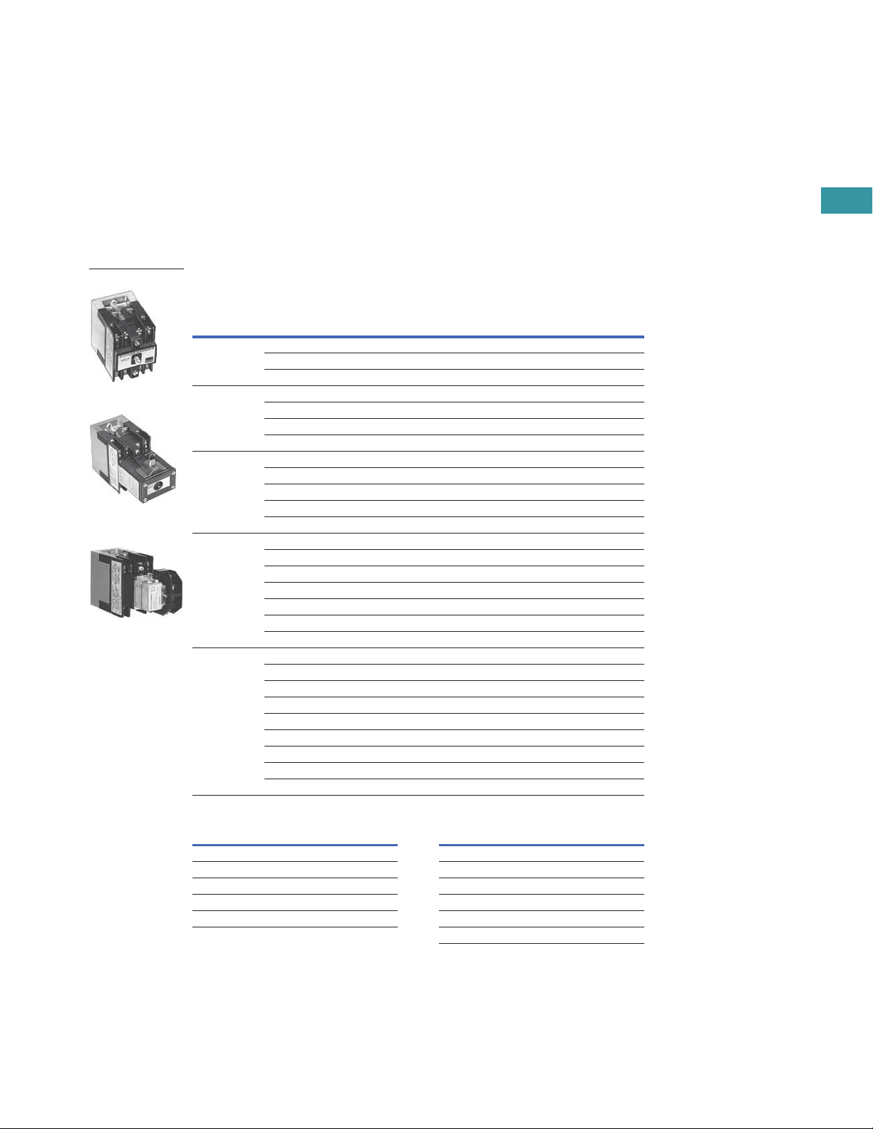
4-Pole
4-Pole with Latch
4-Pole with Pneumatic
Timer Attachment
Page 3
V7-T3-164 Volume 7—Logic Control, Operator Interface and Connectivity Solutions CA08100008E—February 2014
3
3
3
3
3
3
3
3
3
3
3
3
3
3
3
3
3
3
3
3
3
3
3
3
3
3
3
3
3
3
3.7
Control Relays and Timers
Machine Tool Relays
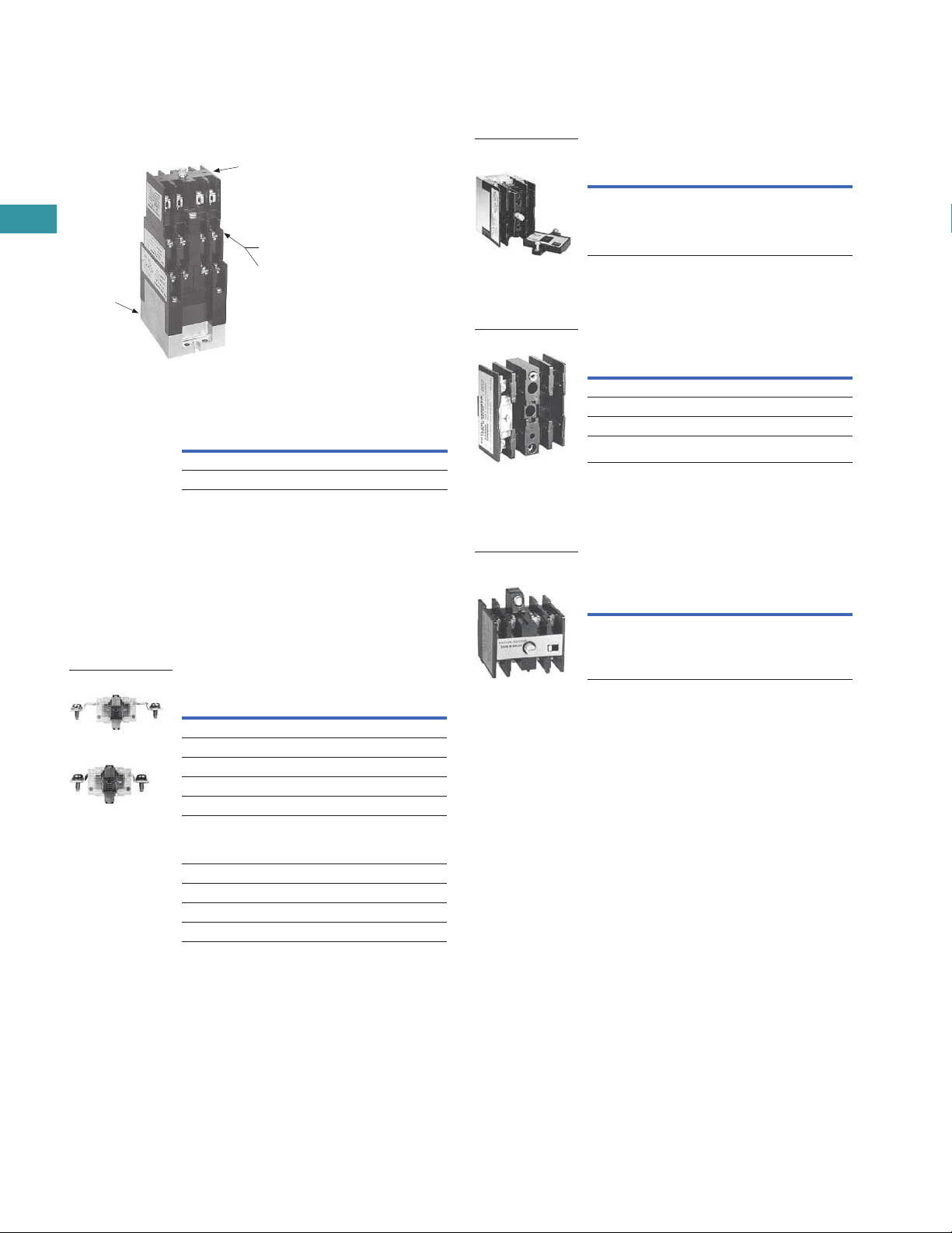
Relay Component Parts Location
Relay with Pneumatic Timer Attachment
Factory Installed (without Relay Contacts)
The relays listed above will
a
ccept up to four catalog
number D26MPR contacts
(convertible—NO or NC) for
instantaneous operation.
Order contacts separately.
For additional information
on timer attachment, see
Page V7-T3-165.
For assembly of relays from
component parts and relay
accessories, see components
tables below.
Separate Contacts
Contact
Positions
1
Timer
Operation
Catalog
Number
2
4 ON delay D26MR005
4 OFF delay D26MR006
D26MB
Relay Base
Assembly
D26MF
Front Attachment
Timer Attachments or
Mechanical Latch
D26MD10
Front Deck
Pneumatic Timer or
Mechanical Latch
D26MF
Front Attachment
Description
Catalog
Number
Convertible Contacts
Rear pole—NO D26MPR
Rear pole—NC D26MPR02
Front pole—NO D26MPF
Front pole—NC D26MPF02
Gold plated
(for low power circuits)
Rear pole—NO D26MPR03
Front pole—NO D26MPF03
Non-Convertible Contacts
Rear pole NO early closing
3
D26MPS
Rear pole NC late opening
3
D26MPL
Rear Pole
Front Pole
Relay Base Assembly (without Poles)
Basic four-pole D26 relay
w
ithout contacts. Provision
for adding one to four poles
as needed, D26MPR,
D26MPL and/or D26MPS
rear pole type.
Front Deck (Convertible Contact Poles)
Provides up to four additional
front pole type D26MPF
contacts. Convertible, NO
to NC.
Four-Pole Front Attachment
(4NO Fixed Circuit)
Can be added to any two- to
e
ight-pole Type M, D26 relay
to provide up to a 12-pole
relay. Four NO, nonconvertible contacts are
included in this assembly.
Notes
1
Number of available instantaneous contact positions (order contacts
separately—Catalog Number D26MPR).
2
Consult Customer Support Center for availability.
3
To obtain overlapping contacts, these two special poles must be used in related circuits.
4
Add magnet coil suffix letter, see Page V7-T3-163. Example: D26MBA.
Description
Catalog
Number
Relay base assembly D26MB
4
Relay Base
Assembly
Description
Catalog
Number
Front Deck with …
1NO contact pole D26MD10
2NO contact poles D26MD20
4NO contact poles D26MD40
Rear Pole
Description
Catalog
Number
Front attachment D26MF
Four-Pole Front
Attachment
Page 4
Volume 7—Logic Control, Operator Interface and Connectivity Solutions CA08100008E—February 2014 V7-T3-165
3
3
3
3
3
3
3
3
3
3
3
3
3
3
3
3
3
3
3
3
3
3
3
3
3
3
3
3
3
3
3.7
Control Relays and Timers
Machine Tool Relays
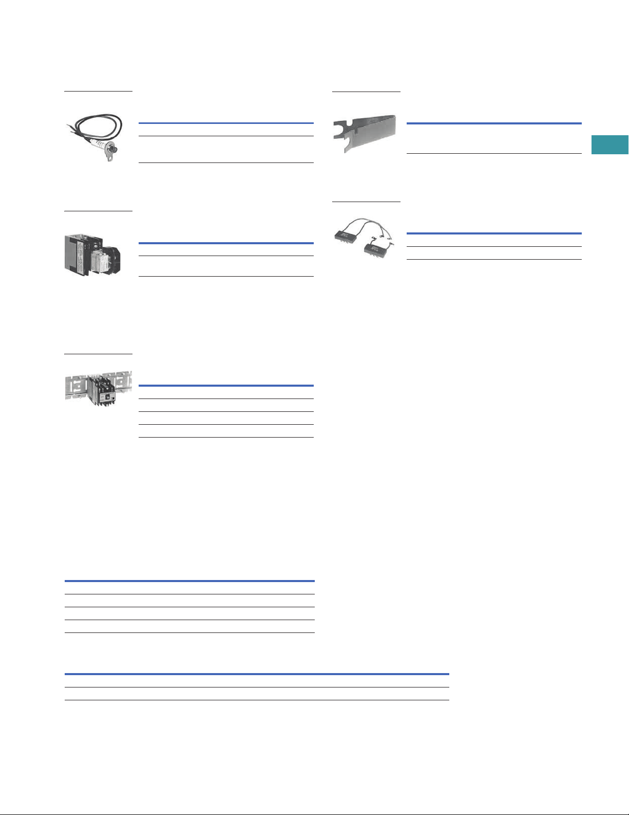
Relay State Indicating Light
Light provided with leads and
b
racket for mounting on two-
to 12-pole relays. May be
used to monitor state
of magnet coil or relay
contact operation.
Pneumatic Timer Attachment
Attachment mounts on any 0to four-pole D26 relay without
latch. Timer unit has DPDT
timed contacts (circuits in
each pole must be the same
polarity). Adjustable timing
range—0.1 to 180 seconds,
repeat accuracy ±10%.
Units are convertible from
OFF delay to ON delay or
vice versa.
Mounting Channel
Pre-spaced mounting for
a
djacent relay installation.
Indexed for cutting to desired
length. Captive mounting
screws provided in channel
for easier installation.
Technical Data and Specifications
General
Note
1
F
or DC contact ratings, see Page V7-T3-169.
Description
Catalog
Number
120 Vac, 50/60 Hz D26MAP120
240 Vac, 50/60 Hz D26MAP240
Relay State
Indicating Light
Description
Catalog
Number
ON delay D26MTE
OFF delay D26MTD
Pneumatic Timer
Attachment
Description
Catalog
Number
10 in length for 4 relays D26MC4
20 in length for 8 relays D26MC8
30 in length for 12 relays D26MC12
40 in length for 16 relays D26MC16
Mounting Channel
Contact Ratings (Amperes) A600
AC Volts
1
Make and
Emergency
Interrupting
Capacity Break
Continuous
Thermal Rating
120 60 6 10
240 30 3 10
480 15 1.5 10
600 12 1.2 10
Coil Power Operating Time
Watts VA
Range in
MillisecondsRelay Inrush Sealed Inrush Sealed
Two- to 12-pole 95.0 9 155 22 Pickup: 6–13
Latch coil 18.5 11 41 17 Dropout: 8–26
Manual Test Accessory
Tool to manually hold relays
in the energized position for
circuitry testing on completed
panel. (10 per box, order in
multiples of
10.)
Transient Suppressor
May be mounted on any
1
20 Vac relay magnet coil
or latch coil or 120 Vdc latch
coil—connects directly across
coil terminals. All DC magnet
coils have a built-in varistor
for transient suppression.
Limits high voltage transients
produced in the circuit when
power is removed from the
coil.
Description
Catalog
Number
Manual test accessory D26MTA
Manual Test Accessory
Description
Catalog
Number
Magnet coil transient suppressor D26MAS1
Latch coil transient suppressor D26MAS2
Transient Suppressor
Page 5

V7-T3-166 Volume 7—Logic Control, Operator Interface and Connectivity Solutions CA08100008E—February 2014
3
3
3
3
3
3
3
3
3
3
3
3
3
3
3
3
3
3
3
3
3
3
3
3
3
3
3
3
3
3
3.7
Control Relays and Timers
Machine Tool Relays
Dimensions
Approximate Dimensions in Inches (mm)
AC and DC D26 Relays
Mounting Channel
Note: C
hannel mounts through keyholes with #10 screws
(two each end and one every fourth relay). Relays mount with screws
captive in channel. All screws must be tightened firmly.
AC Relay
D
26
DC Relay
D26 Dimension A
Ship. Wt.
Lbs (kg)
1–4 poles 1–3 poles 4.00 (101.6) 2.5 (1.1)
1–4 poles with timer D26 or D87 1–3 poles with timer D26 or D87 6.00 (152.4) 3.3 (1.5)
1–4 poles with latch 1–2 poles with latch 6.13 (155.7) 3.5 (1.6)
1–4 poles with D26MF 1–3 poles with D26MF 5.81 (147.6) 2.8 (1.3)
5–8 poles 4–7 poles 5.25 (133.4) 2.8 (1.3)
5–8 poles with timer D87 4–7 poles with timer D87 7.25 (184.2) 3.5 (1.6)
5–8 poles with latch 3–6 poles with latch 7.31 (185.7) 3.8 (1.7)
9–12 poles 8–11 poles 7.00 (177.8) 3.0 (1.4)
Catalog
Number Dimension A Dimension B
D26MC16 40 (1016) 37.5 (952.5)
D26MC12 30 (762) 27.5 (698.5)
D26MC8 20 (508) 17.5 (444.5)
D26MC4 10 (254) 7.5 (190.5)
2.38 (60.5)
Max.
D26MAS2
D26MAS1
0.75
(19.1)
3.13
(79.5)
0.44
(11.2)
0.44
(11.2)
3.50
(88.9)
A
1 Slot
#10 Screw
2 Holes
#10 Screw
2.50
(63.5)
2.50
(63.5)
2.38
(60.5)
B
0.69
(17.5)
1.06
(26.9)
A
1.25
(31.8)
3.63
(92.2)
1.38
(35.1)
0.38
(9.7)
Type
M
Relay
D26
 Loading...