

Page 1

Control Relays and Timers
D8 Series Relay
General Purpose Plug-In Relays
3.4
D8 Series
Product Description
The D8 Series power relays
are perfect for loads up to 30
A, with versions for flange
mounting and e-clip mounting
available.
Features
●
Allows switching of 25 A
and 30 A loads
●
A high-capacity, highwithstand voltage relay
compatible with
momentary voltage drops
●
No contact chattering for
momentary voltage drops
up to 50% of rated voltage
●
UL Class B construction
standard
●
Wide-range AC-activated
coil that handles 100 to 120
Vac at either 50
or 60 Hz
●
Panel, DIN rail and flange
mounting
Contents
Description Page
D1RR/D1RF Series . . . . . . . . . . . . . . . . . . . . . . . . . V7-T3-53
D2RR/D2RF Series . . . . . . . . . . . . . . . . . . . . . . . . . V7-T3-57
D3RR/D3RF Series . . . . . . . . . . . . . . . . . . . . . . . . . V7-T3-67
D4 Series . . . . . . . . . . . . . . . . . . . . . . . . . . . . . . . . V7-T3-76
D5RR/D5RF Series . . . . . . . . . . . . . . . . . . . . . . . . . V7-T3-80
D7PR/D7PF Series . . . . . . . . . . . . . . . . . . . . . . . . . V7-T3-89
D8 Series
Catalog Number Selection . . . . . . . . . . . . . . . . V7-T3-104
Product Selection . . . . . . . . . . . . . . . . . . . . . . . V7-T3-104
Technical Data and Specifications . . . . . . . . . . . V7-T3-105
Dimensions . . . . . . . . . . . . . . . . . . . . . . . . . . . . V7-T3-105
D9 Series . . . . . . . . . . . . . . . . . . . . . . . . . . . . . . . . V7-T3-108
Accessories . . . . . . . . . . . . . . . . . . . . . . . . . . . . . . V7-T3-112
Standards and Certifications
File # E1491
File # LR701520
3
3
3
3
3
3
3
3
3
3
3
3
3
3
3
3
3
3
3
3
3
3
3
3
3
3
3
3
3
3
3
3
3
3
3
3
3
3
3
3
Volume 7—Logic Control, Operator Interface and Connectivity Solutions CA08100008E—July 2015 www.eaton.com V7-T3-103
Volume 7—Logic Control, Operator Interface and Connectivity Solutions CA08100008E—July 2015 www.eaton.com V7-T3-103
3
3
3
3
3
3
3
3
3
3
3
3
3
3
3
3
3
3
3
3
Page 2
Control Relays and Timers
D 8 P R 6 T E A
Family Type
D8PR
Contact Configuration
6 = SPST-NO
7 = DPST-NO
Options
TE = E-bracket
TF = Flange mount
Coil Voltage
A = 120 Vac
B = 240 Vac
R1 = 12 Vdc
T = 24 Vac
T1 = 24 Vdc
D8 Series Relay
3.4
Catalog Number Selection
3
3
D8 Series
3
3
3
3
3
3
3
3
3
3
3
3
3
3
3
3
Product Selection
3
3
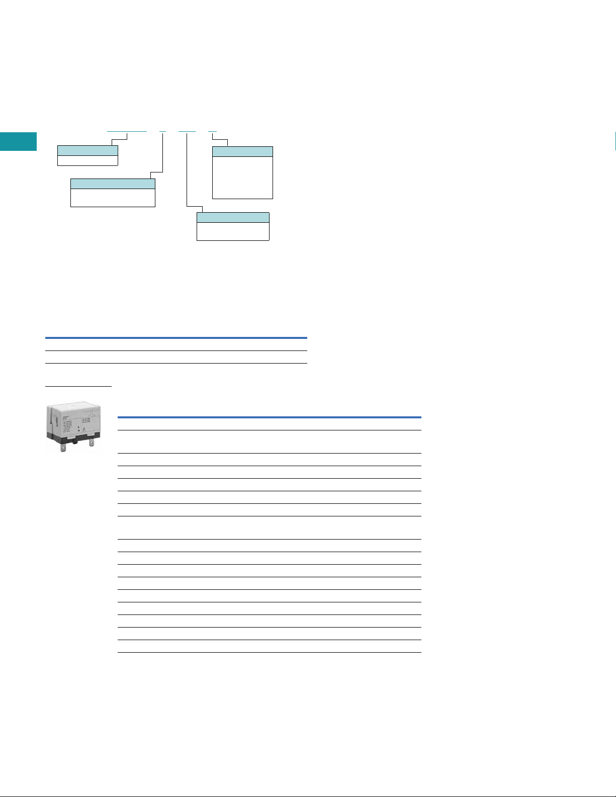
D8 Relay/Socket Quick Reference
3
3
Relay
Typ e
3
3
D8PR6TE D8PA5 D8PA1 D8PA2
D8PR7TE D8PA5 D8PA1 D8PA2
3
3
1
General Purpose Plug-In Relays
Mounting
Bracket
Adapter Track/
Panel Mount
Front Connecting
Sockets Track/
Panel Mount
3
3
3
3
3
3
3
3
3
3
3
3
3
3
3
3
3
3
3
3
3
3
3
3
3
3
3
3
3
3
3
3
3
3
2
D8 Series
Typ e
SPST E-Bracket
Coil voltage
24 Vac 1 D8PR6TET
24 Vdc 1 D8PR6TET1
SPST Flange Mount
120 Vac 1 D8PR6TFA
24 Vdc 1 D8PR6TFT1
DPST E-Bracket
Coil voltage
120 Vac 1 D8PR7TEA
DPST Flange Mount
120 Vac 1 D8PR7TFA
24 Vdc 1 D8PR7TFT1
Sockets
DIN rail adapter 10 D8PA1
Screw terminal adapter 10 D8PA2
Bracket adapter 10 D8PA5
Accessory
DIN rail end stop 100 PFP-M
Notes
1
V7-T3-104 Volume 7—Logic Control, Operator Interface and Connectivity Solutions CA08100008E—July 2015 www.eaton.com
V7-T3-104 Volume 7—Logic Control, Operator Interface and Connectivity Solutions CA08100008E—July 2015 www.eaton.com
For deciphering catalog numbers. Do not use for ordering as not all combinations are readily available.
2
Additional coil voltages available—consult Sales Office or Customer Support Center.
Standard
Pack
Catalog
Number
Page 3

Control Relays and Timers
Two 0.18 (4.5) Dia. Holes
or M4 Tapped Holes
2.70 (68.5) Max.
1.32 (33.5)
Max.
0.08 (2.0)
1.85
(47.0)
Max.
0.18
(4.5)
0.03
(0.8)
2.36 (60.0)
1.99 (50.5)
Max.
0.25 (6.4)
0.43
(11.0)
0.12 (3.0)
01
46
2.362 0.007
(60.0 0.2)
Mounting Holes
(Bottom View)
Terminal Arrangement/
Internal Connections
(Top View)
General Purpose Plug-In Relays
3.4
Technical Data and Specifications
Coil Resistance
Coil Voltage Ohms mA
24 Vac 303 71
110/120 Vac 5260 20.4
220/240 Vac 21,000 10.2
12 Vdc 75 158
24 Vdc 303 79
D8 Relays
Description D8PR6 D8PR7
Rated load 220 Vac 30 A 220 Vac 25 A
Carry current 30 A 25 A
Max. operating voltage 250 Vac 250 Vac
Max. switching current 30 A 25 A
Contact material AgCdO AgCdO
Max. switching capacity 6600 VA 5500 VA
Min. permissible load 100 mA at 5 Vdc 100 mA at 5 Vdc
Mechanical life (min.) 5,000,000 operations 5,000,000 operations
Electrical life at all contact ratings (min.) 100,000 operations 100,000 operations
Maximum hp ratings 1-1/2 hp (120 Vac)
3 hp (240/265/277 Vac)
Coil Data
Coil Voltage Must Operate Must Release Maximum Voltage
24 Vdc/Vac, 12 Vdc 75% maximum 15% minimum 110%
120 Vac 75 V 18 V 132 V
240 Vac 150 V 36 V 264 V
1-1/2 hp (120 Vac)
3 hp (240/265/277 Vac)
3
3
3
3
3
3
3
3
3
3
3
3
3
3
3
3
3
3
3
3
3
3
3
3
3
3
3
3
3
3
3
3
Dimensions
Approximate Dimensions in Inches (mm)
D8PR6TF
Volume 7—Logic Control, Operator Interface and Connectivity Solutions CA08100008E—July 2015 www.eaton.com V7-T3-105
Volume 7—Logic Control, Operator Interface and Connectivity Solutions CA08100008E—July 2015 www.eaton.com V7-T3-105
3
3
3
3
3
3
3
3
3
3
3
3
3
3
3
3
3
3
3
3
3
3
3
3
3
3
3
3
Page 4

Control Relays and Timers
Two 0.18 (4.5) Dia. Holes
or M4 Tapped Holes
2.70 (68.5) Max.
1.32 (33.5)
Max.
0.08 (2.0)
1.85
(47.0)
Max.
0.18
(4.5)
0.03
(0.8)
2.36 (60.0)
1.99 (50.5)
Max.
0.25 (6.4)
0.43
(11.0)
0.12
(3.0)
01
24
68
2.362 0.007
(60.0 0.2)
Mounting Holes
(Bottom View)
Terminal Arrangement/
Internal Connections
(Top View)
Two 0.18 (4.5) Dia. Holes
or M4 Tapped Holes
1.32 (33.5)
Max.
0.08 (2.0)
2.09
(53.0)
Max.
0.03
(0.8)
2.07 (52.5) Max.
1.99
(50.5) Max.
0.25 (6.4)
0.43
(11.0)
01
46
1.574 0.003
(40.0 0.1)
Mounting Holes
(Bottom View)
Terminal Arrangement/
Internal Connections
(Top View)
Two 0.18 (4.5) Dia. Holes
or M4 Tapped Holes
1.32 (33.5)
Max
0.08 (2.0)
2.09
(53.0)
Max.
0.03
(0.8)
2.07 (52.5) Max.
1.99
(50.5) Max.
0.25 (6.4)
01
24
68
1.574 0.003
(40.0 0.1)
Mounting Holes
(Bottom View)
Terminal Arrangement/
Internal Connections
(Top View)
0.43
(11.0)
2.19 (55.5)
Max.
2.03
(51.5)
Max.
0.20
(5.0)
1.574 0.003
(40.0 0.1)
1.39 (35.2)
Max.
0.57
(14.5)
1.574 0.003
(40.0 0.1)
Two M4 or
0.18 (4.5) Dia. Holes
Mounting Holes
(Bottom View)
3.4
Approximate Dimensions in Inches (mm)
3
3
D8PR7TF
3
3
3
3
3
3
3
3
3
3
3
3
3
3
D8PR6TE with D8PA5 Bracket Attached
3
3
3
3
3
3
General Purpose Plug-In Relays
3
3
3
3
3
3
D8PR7TE with D8PA5 Bracket Attached
3
3
3
3
3
3
3
3
3
3
3
3
3
3
D8PA1
3
3
3
3
3
3
3
3
3
3
3
3
3
3
3
3
3
3
Note: Minimum spacing around relay = 0.20 inches (5 mm).
V7-T3-106 Volume 7—Logic Control, Operator Interface and Connectivity Solutions CA08100008E—July 2015 www.eaton.com
V7-T3-106 Volume 7—Logic Control, Operator Interface and Connectivity Solutions CA08100008E—July 2015 www.eaton.com
Page 5

Control Relays and Timers
2.19 (55.5)
Max.
0.36 (9.2)
2.03
(51.5)
Max.
0.20
(5.0)
1.574 0.003
(40.0 0.1)
1.81 (46.0)
Max.
0.98
(25.0)
1.574 0.003
(40.0 0.1)
Two M4 or
0.18 (4.5) Dia. Holes
Two M3.5 Screws
for Coil
Four M4 Screws
for Contact
0.31 (8.0)
Mounting Holes
(Bottom View)
0.78
(19.7)
0.12
(3.0)
0.17
(4.4)
0.20
(5.0)
0.20
(5.0)
1.20 (50.0)
1. 18
(30.0)
1.81
(46.0)
1.57
(40.0)
1.02
(26.0)
0.94
(24.0)
0.70
(17.8)
0.94
(24.0)
0.27
(7.0)
0.39
(10.0)
Two
0.18 (4.5)
Dia. Holes
1.574 0.003
(40.0 0.1)
Mounting
Holes
(Bottom View)
Two M4 or 0.18 (4.5)
Dia. Holes
General Purpose Plug-In Relays
3.4
Approximate Dimensions in Inches (mm)
D8PA2
D8PA5 PFP-M DIN Rail End Stop
M4 Spring Washer
M4 x 8 Pan
Head Screw
0.45
(11.5)
0.39
(10.0)
0.19
(4.8)
0.39
(10.0)
1.97
(50.0)
0.24
(6.2)
0.07
(1.8)
0.07
(1.8)
0.05
(1.3)
1.39
(35.3)
1.47
(37.3)
3
3
3
3
3
3
3
3
3
3
3
3
3
3
3
3
3
3
3
3
3
3
3
3
3
3
3
3
3
3
3
3
3
3
Volume 7—Logic Control, Operator Interface and Connectivity Solutions CA08100008E—July 2015 www.eaton.com V7-T3-107
Volume 7—Logic Control, Operator Interface and Connectivity Solutions CA08100008E—July 2015 www.eaton.com V7-T3-107
3
3
3
3
3
3
3
3
3
3
3
3
3
3
3
3
3
3
3
3
3
3
3
3
3
3
 Loading...