

Page 1
Definite Purpose Contactors and Starters
25–60A, Single- and Three-Phase—A25, B25
Incomplete catalog number
A25CNC30 A
Magnet coil suffix
Starters
4.3
25–60A, Single- and Three-Phase—A25, B25
Product Description
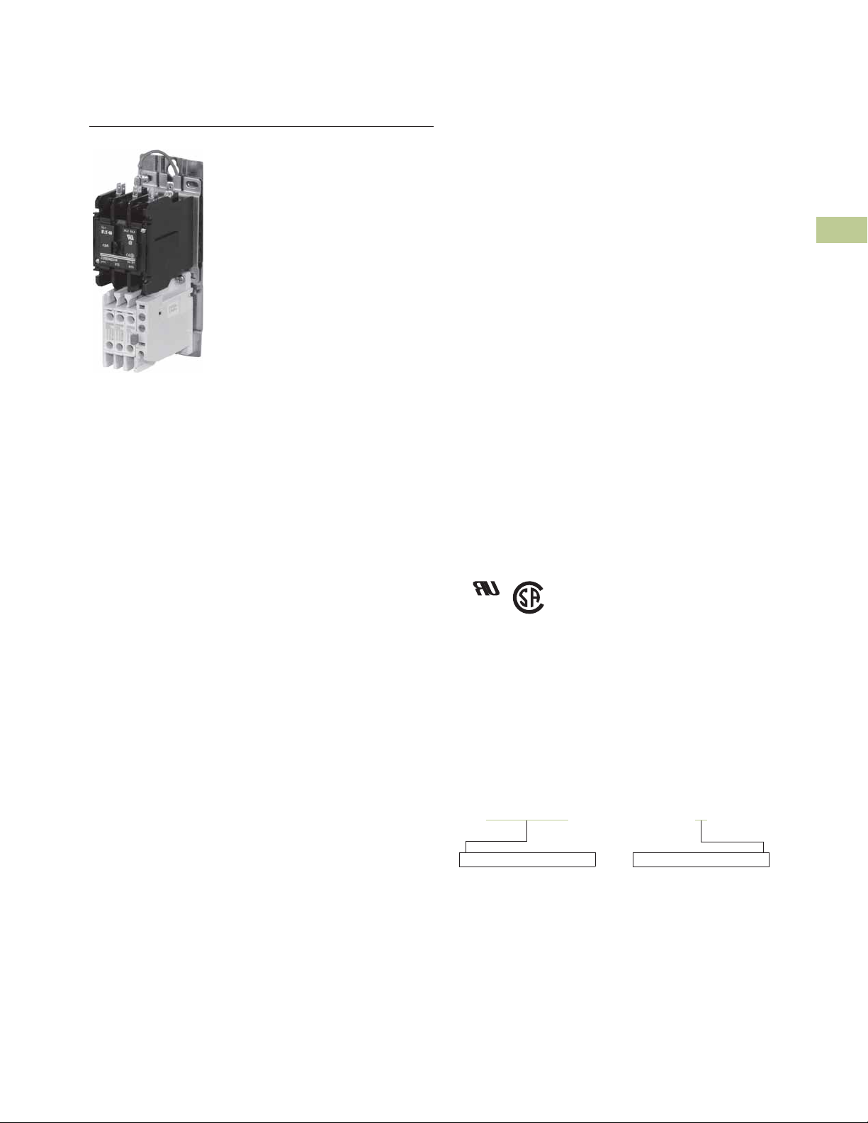
A25 and B25 Definite
Purpose Starters from Eaton’s
Electrical Sector combine the
features and flexibility of the
C25 Definite Purpose
Contactors and Freedom
Series Bi-metallic Ambient
Compensated Overload
Relays mounted on a common
mounting plate.
Features and Benefits
Overload Relay
●
Selectable manual or
automatic reset operation
●
Interchangeable heater
packs adjustable ±24% to
match motor FLA and
calibrated for use with 1.0
and 1.15 service factor
motors
●
Class 10 or 20 heater packs
●
Bimetallic, ambient
compensated operated.
Trip free mechanism
●
Electrically isolated NO-NC
contacts (pull RESET
button to test)
●
Overload trip indication
●
Shrouded or fingerproof
terminals to reduce
possibility of electrical
shock
●
Single-phase sensitivity
Contents
Description Page
25–60A, Single- and Three-Phase—A25, B25
Product Selection . . . . . . . . . . . . . . . . . . . . . . . V5-T4-24
Accessories . . . . . . . . . . . . . . . . . . . . . . . . . . . V5-T4-26
Technical Data and Specifications . . . . . . . . . . V5-T4-27
Trip Curves . . . . . . . . . . . . . . . . . . . . . . . . . . . . V5-T4-28
Wiring Diagrams . . . . . . . . . . . . . . . . . . . . . . . . V5-T4-28
Dimensions . . . . . . . . . . . . . . . . . . . . . . . . . . . V5-T4-29
15–45A, Single- and Three-Phase—A27, B27 . . . . V5-T4-30
15–75A, Single- and Three-Phase—A30, B30 and
C440/XT Electronic Overload Relay . . . . . . . . . . V5-T4-38
Standards and Certifications
●
UL Recognized
Components UL File
#E-1491, Guide NLDX2
●
CSA Certified Components
File #LR353, Guide
380W-1.14 Class 3211 04
Catalog Number Selection
25–60A, Single- and Three-Phase—A25, B25
4
4
4
4
4
4
4
4
4
4
4
4
4
4
4
4
4
4
4
4
4
4
4
When Ordering Specify
●
Catalog number plus magnet coil suffix, see Page V5-T4-24
Example, order catalog number A25CNC30A
●
Heater packs for specific FLA of motor,
see Pages V5-T4-26 and V5-T4-27
Volume 5—Motor Control and Protection CA08100006E—August 2018 V5-T4-23
4
4
4
4
4
4
4
Page 2
4.3
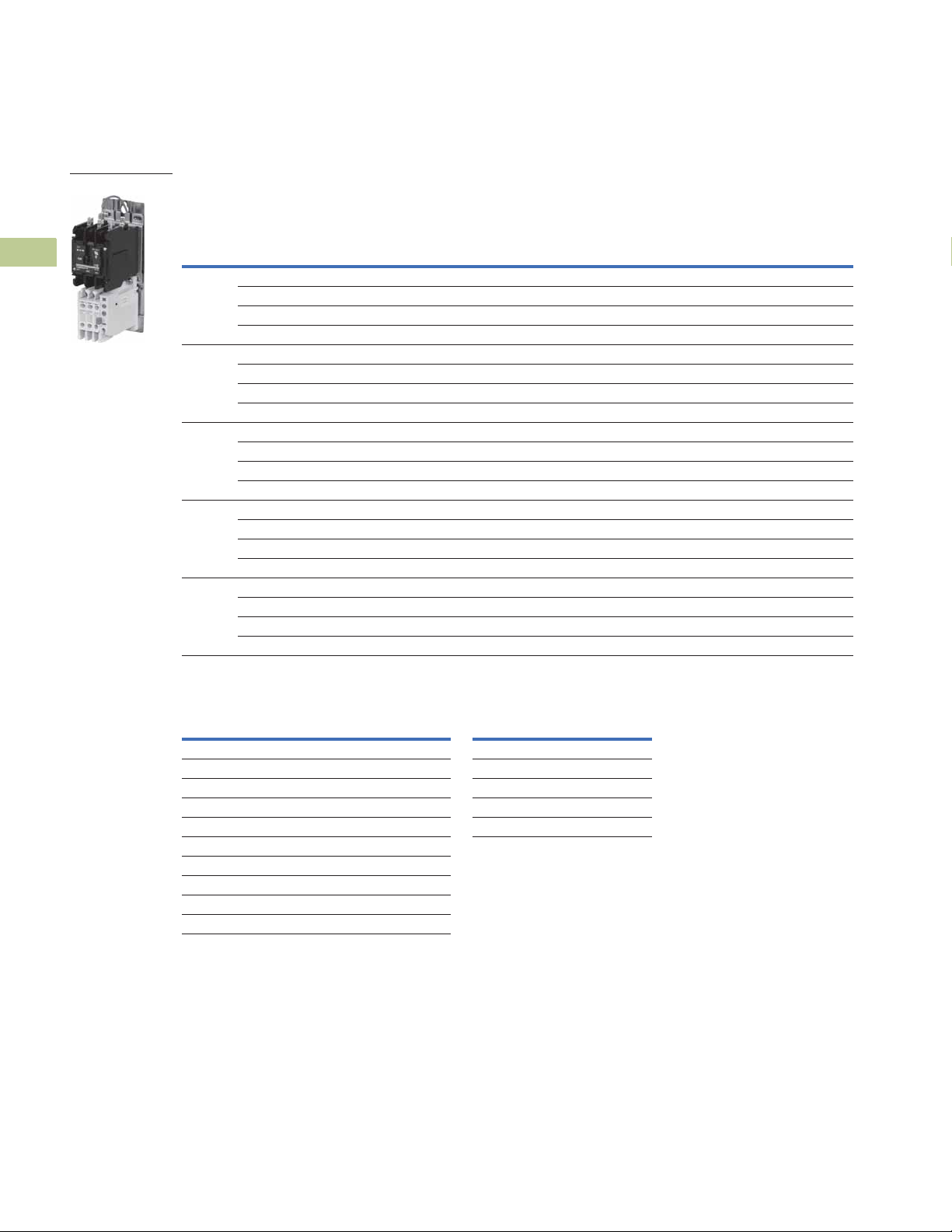
A25 Starter
Product Selection
4
4
4
4
4
4
4
4
4
4
4
4
4
4
4
4
Definite Purpose Contactors and Starters
Starters
Single- and Three-Phase Starters—Open Type
Single-Phase
Ampere Rating
Inductive
Full Load
25 115 150 2 — 1.5 — B25CNC25_ B25SNC25_ A25CNC25_ A25SNC25_
30 115 180 2 — 1.5 — B25CNC30_ B25SNC30_ A25CNC30_ A25SNC30_
40 115 240 3 — 2.2 — B25CNE40_ B25SNE40_ A25CNE40_ A25SNE40_
50 115 300 — — — — N/A N/A A25CNE50_ A25SNE50_
60 115 360 — — — — N/A N/A A25CNE60_ A25SNE60_
Line
Voltage
230 150 3 7-1/2 2.2 5.5 B25CNC25_ B25SNC25_ A25CNC25_ A25SNC25_
460 125 — 10 — 7.5 B25CNC25_ B25SNC25_ A25CNC25_ A25SNC25_
575 100 — 10 — 7.5 B25CNC25_ B25SNC25_ A25CNC25_ A25SNC25_
230 180 5 10 3.7 7.5 B25CNC30_ B25SNC30_ A25CNC30_ A25SNC30_
460 150 — 15 — 11 B25CNC30_ B25SNC30_ A25CNC30_ A25SNC30_
575 120 — 15 — 11 B25CNC30_ B25SNC30_ A25CNC30_ A25SNC30_
230 240 7-1/2 10 5.5 7.5 B25CNE40_ B25SNE40_ A25CNE40_ A25SNE40_
460 200 — 20 — 15 B25CNE40_ B25SNE40_ A25CNE40_ A25SNE40_
575 160 — 20 — 15 B25CNE40_ B25SNE40_ A25CNE40_ A25SNE40_
230 300 — 15 — 11 N/A N/A A25CNE50_ A25SNE50_
460 250 — 30 — 22 N/A N/A A25CNE50_ A25SNE50_
575 200 — 30 — 22 N/A N/A A25CNE50_ A25SNE50_
230 360 — 20 — 15 N/A N/A A25CNE60_ A25SNE60_
460 300 — 40 — 30 N/A N/A A25CNE60_ A25SNE60_
575 240 — 40 — 30 N/A N/A A25CNE60_ A25SNE60_
Locked
Rotor
Maximum Motor
(hp)
SinglePhase
ThreePhase
Maximum Motor
(kW)
SinglePhase
ThreePhase
Common
Control
Catalog
Number
12
Separate
Control
Catalog
3
Number
3
Three-Phase
Common
Control
Catalog
Number
1
Separate
Control
Catalog
3
Number
3
4
4
4
4
4
4
4
4
4
4
4
4
4
4
Magnet Coil Suffix
Voltage
60 Hertz 50 Hertz Coil Suffix
4
AC
12 12 R 12 1R
24 24 T 24 1T
5
110–120
208–240 208–240 B 120 1A
6
240
277 — H
— 380–415 L
440–480 440–480 C
550–600 550–600 D
Notes
1
Starters do not include heater packs. Select heater pack from tables, see Pages V5-T4-26 and V5-T4-27.
2
Set of three heater packs required for single-phase applications.
3
Incomplete catalog number. Replace underscore (_) with magnet coil suffix from table above.
4
Class H AC coils available as option for 15A–50A contactor. Add 2 before AC coil suffix letter.
5
104–120V 50/60 Hz for 60A contactor.
6
Available through 50A.
7
Starters with DC coils include an early breaking auxiliary contact, C320KGD1. See Page V5-T4-62 for more detail.
5
110–120
220 J
A 48 1W
Voltage
60 Hertz Coil Suffix
7
DC
V5-T4-24 Volume 5—Motor Control and Protection CA08100006E—August 2018
Page 3

Definite Purpose Contactors and Starters
AD
CB
1. 0
Service
Factor
1. 15
Service
Factor
Starters
4.3
Overload Relay
General
Overload relays are provided
to protect motors, motor
control apparatus and motorbranch circuit conductors
against excessive heating
due to motor overloads and
failure to start. This definition
does not include: 1) motor
circuits over 600 volts, 2)
short-circuits, 3) ground faults
and 4) fire pump control.
(NEC Art. 430-31)
Time Current
Characteristics
The time-current
characteristics of an overload
relay is an expression of
performance which defines
its operating time at various
multiples of its current
setting. Tests are run at
Underwriters Laboratory (UL)
in accordance with NEMA
Standards and the NEC.
UL requires—
●
When tested at 100
percent of its current
rating, the overload relay
shall trip ultimately
●
When tested at 200
percent of its current
rating, the overload relay
shall trip in not more than 8
minutes
●
When tested at 600
percent of its current
rating, the overload relay
shall trip in not more than
10 or 20 seconds,
depending on the Class of
the relay or heater packs
“Current Rating” is defined
as the minimum current at
which the relay will trip. Per
NEC, an overload must
ultimately trip at 125% of FLA
(Full Load Amperes) current
(heater) setting for a 1.15
service factor motor and
115% FLA for a 1.0 service
factor motor.“Current
Setting” is defined as the
FLA of the motor and thus
the overload heater pack
setting.
Example: 600% of current
rating is defined as 750%
(600 x 1.25) of FLA current
(heater) setting for a 1.15
service factor motor. A 10
ampere heater setting must
trip in 20 seconds or less at
75 amperes motor current for
a Class 20 relay.
Overload Relay Setting
FLA Dial Adjustment—
For motors having a 1.15
service factor, rotate the FLA
adjustment dial to correspond
to the motor’s FLA rating.
Estimate the dial position
when the motor FLA falls
between two letter values as
shown in the example.
For motors having a 1.0
service factor, rotate the FLA
dial single-half position
counterclockwise (CCW).
Manual/Automatic Reset—
The overload relay is factory
set at M for manual reset
operation. For automatic
reset operation, turn the reset
adjustment dial to the A
position as shown in the
illustration.
Automatic reset is not
intended for two-wire control
devices.
Test for Trip Indication—
To test overload relay for trip
indication when in manual
reset, pull out the blue RESET
button. An orange flag will
appear indicating that the
device has tripped. Push
RESET button in to reset.
4
4
4
4
4
4
4
4
4
4
4
4
4
4
FLA Dial Adjustment Reset Adjustment Dial
A
M
Example of 12.0 FLA
setting for heater pack
number H2011B showing
position for 1.0 or 1.15
service factor motors.
Replacement Overload with Connectors
Starter Size Overload Part Number
25 and 30A 10-7125
40 and 50A 10-7132
60A 10-7131
Example of setting for manual
reset.
4
4
4
4
4
4
4
4
4
4
4
4
4
4
4
4
Volume 5—Motor Control and Protection CA08100006E—August 2018 V5-T4-25
Page 4

Definite Purpose Contactors and Starters
Locking Cover
4.3
Accessories
4
Contactor Accessories, see Pages V5-T4-11 and V5-T4-12.
Locking Cover for Overload Relay
4
Snap-on transparent or opaque plastic panel for covering access port to the overload relay trip
setting dial—helps prevent accidental or unauthorized changes to trip and reset setting.
4
4
4
4
4
4
4
Separate Enclosures
4
4
4
Starters
Locking Cover for Overload Relay
Minimum Order
Description
Clear cover, no accessibility 50 C320PC3
Gray cover, no accessibility, with auto only nib 50 C320PC4
Gray cover, no accessibility, with manual only nib 50 C320PC5
Gray cover with FLA dial accessibility, A, B, C, D positions
and auto only nib
Gray cover with FLA dial accessibility, A, B, C, D positions
and manual only nib
Separate Enclosures—NEMA 1
Application Catalog Number
25 and 30A C799B11
40, 50 and 60A C799B13
Quantity
(Std. Pkg.) Catalog Number
50 C320PC6
50 C320PC7
4
4
4
4
4
4
4
4
4
4
4
4
4
4
4
4
4
4
Heater Packs
Fast Trip—Class 10 Heater Packs
Manual or Automatic Reset
Heater packs are shipped three to a carton.
Catalog numbers listed below are for three heater packs.
Fast Trip Ratings
Motor Full Load Ampere Rating
Dial Position
ABCD
0.26 0.313 0.367 0.42 H2101B-3
0.384 0.464 0.543 0.623 H2102B-3
0.57 0.688 0.806 0.924 H2103B-3
0.846 1.02 1.2 1.37 H2104B-3
1.28 1.55 1.83 2.1 H2105B-3
1.92 2.33 2.74 3.15 H2106B-3
2.3 2.79 3.28 3.77 H2107B-3
3.38 4.1 4.82 5.54 H2108B-3
4.96 6.03 7.09 8.16 H2109B-3
7.07 8.58 10.1 11.6 H2110B-3
9.6 11.2 12.8 14.4 H2111B-3
14.4 17.5 20.7 23.8 H2112B-3
18.7 21.8 25 28.1 H2113B-3
23.5 27.3 31 34.8 H2114B-3
28.3 32.6 37 41.3 H2115B-3
36.6 42.3 48.1 53.8 H2116B-3
53.8 60.8 67.9 74.9 H2117B-3
Trip Curves, see Page V 5-T4-28.
Notes
1
For motor full load amperes between listed values, adjust dial clockwise for higher or counterclockwise for lower motor currents. The currents listed are for 1.5 service factor motors.
A position adjustment is provided for 1.0 service factor motors.
2
Set of three heater packs are required for both single- and three-phase applications.
1
Catalog Number
(Includes Three Heater
Packs)
2
V5-T4-26 Volume 5—Motor Control and Protection CA08100006E—August 2018
Page 5

Definite Purpose Contactors and Starters
Starters
4.3
Standard Trip—Class 20 Heater Packs
Manual or Automatic Reset
Heater packs are shipped three to a carton.
Catalog numbers listed below are for three heater packs.
Standard Trip Ratings
Motor Full Load Ampere Rating
Dial Position
ABCD
0.254 0.306 0.359 0.411 H2001B-3
0.375 0.452 0.53 0.607 H2002B-3
0.56 0.676 0.791 0.907 H2003B-3
0.814 0.983 1.15 1.32 H2004B-3
1.2 1.45 1.71 1.96 H2005B-3
1.79 2.16 2.53 2.9 H2006B-3
2.15 2.6 3.04 3.49 H2007B-3
3.23 3.9 4.56 5.23 H2008B-3
4.55 5.5 6.45 7.4 H2009B-3
6.75 8.17 9.58 11 H2010B-3
9.14 10.8 12.4 14 H2011B-3
14 16.9 19.9 22.8 H2012B-3
18.7 22.7 26.7 30.7 H2013B-3
23.5 28.5 33.5 38.5 H2014B-3
29 34 39.1 44.1 H2015B-3
39.6 45.5 51.5 57.4 H2016B-3
53.9 60.9 67.9 74.9 H2017B-3
Trip Curves, see Page V5-T4-28.
1
Catalog Number
(Includes Three Heater
Packs)
4
4
4
2
4
4
4
4
4
4
4
4
4
4
4
4
Technical Data and Specifications
Terminal Wire Sizes
Line Side (Contactor)
Terminal Type Power Terminals Coil Terminals
Screw/pressure plate 8–14 AWG 12–16 AWG
Box lug: 25–50A 4–14 AWG 12–16 AWG
Box lug: 60A 3–14 AWG 12–16 AWG
Power Terminals—Load—Cu Only (Stranded or Solid)
Terminal Range Torque Rating
25 and 30A 14–6 AWG 20 lb-in (14–10 AWG)
40, 50 and 60A 14–2 AWG 35 lb-in (14–10 AWG)
Control Terminals—Cu Only
12–16 AWG stranded, 12–14 AWG solid
Notes
1
For motor full load amperes between listed values, adjust dial clockwise for higher or counterclockwise for lower motor currents. The currents listed are for 1.5 service factor motors.
A position adjustment is provided for 1.0 service factor motors.
2
Set of three heater packs are required for both single- and three-phase applications.
3
Line side (contactor) torque ratings can be found on Page V5-T4-14.
3
Wire Range—Solid or Stranded
40 lb-in (8 AWG)
45 lb-in (6–4 AWG)
50 lb-in (3–2 AWG)
4
4
4
4
4
4
4
4
4
4
4
4
4
4
Volume 5—Motor Control and Protection CA08100006E—August 2018 V5-T4-27
4
Page 6
Definite Purpose Contactors and Starters
0
1
2
3
4
5
10
20
30
40
50
100
200
300
400
500
1000
2000
3000
4000
5000
10,000
246810
From
Hot Start
From
Cold Start
Multiples of Current Setting
Trip Time
(Seconds)
0
1
2
3
4
5
10
20
30
40
50
100
200
300
400
500
1000
2000
3000
4000
5000
10,000
246810
From
Hot Start
From
Cold Start
Multiples of Current Setting
Trip Time
(Seconds)
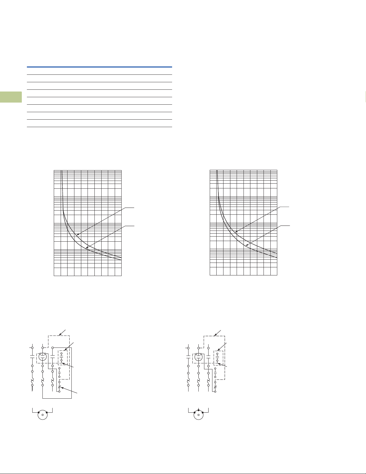
1NO Aux. Contact
(When Supplied)
Reset
Wire “D”
(Supplied with
1NO Aux. Contact)
Wire “C”
(Supplied with Common Control)
1
13
14
L1 L2
T1
4/T22/T1
T2
AC Motor
98
97
96
95
4.3
Overload Relay UL/CSA Contact Ratings Control Circuit
4
AC Volts 120V 240V 480V 600V
NC Contact B600
4
Make and break 30A 15A 7.5A 6A
Break 3A 1.5A 0.75A 0.6A
4
Continuous 5A 5A 5A 5A
4
NO Contact C600
Make and break 15A 7.5A 3.375A 3A
4
Break 1.5A 0.75A 0.375A 0.3A
Continuous 2.5A 2.5A 2.5A 2.5A
4
4
Trip Curves
4
Bimetallic Ambient Compensated Overload Relay—25°C Open Rating
Class 10 Overload Relay Class 20 Overload Relay
4
4
4
Starters
4
4
4
4
4
4
4
4
Wiring Diagrams
4
Single-Phase Connections Three-Phase Connections
4
4
4
4
4
4
4
4
4
4
V5-T4-28 Volume 5—Motor Control and Protection CA08100006E—August 2018
T2
6/T32/T1 4/T2
T3
Wire “C”
1NO Aux. Contact
13
14
98
97
96
95
(When Supplied)
Wire “D”
(Supplied with
1NO Aux. Contact)
(Supplied with Common Control)
L1 L2 L3
1
T1
AC Motor
Page 7
Definite Purpose Contactors and Starters
G D
C
Mtg. for #10-32 Screw
AHH
B
E
Starters
4.3
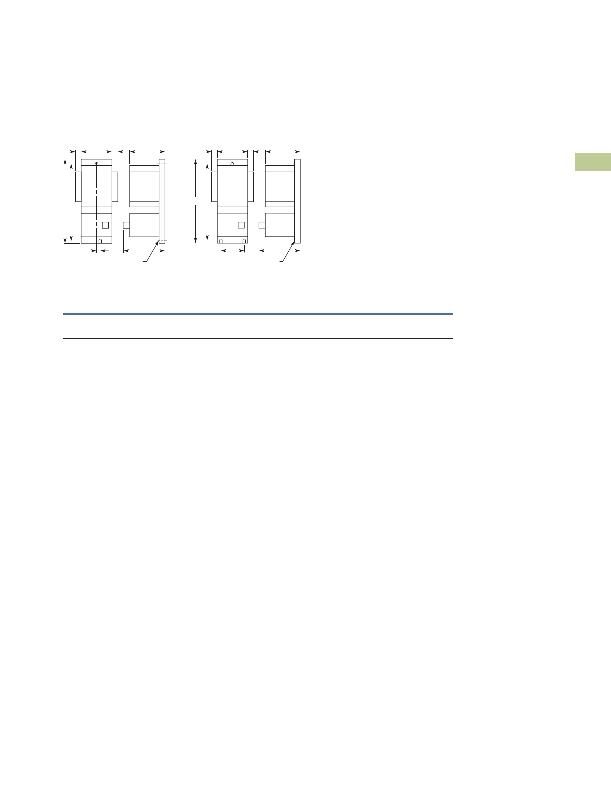
Dimensions
Approximate Dimensions in Inches (mm)
A25 and B25 Starers—Open Type
25 and 30 Ampere
Dimensions and Shipping Weights
Ampere Size
25 and 30 2.50 (64.0) 7.14 (181.0) 3.56 (90.4) 3.69 (93.7) 6.55 (166.0) 0.20 (5.1) 0.54 (13.7) 1.8 (0.8)
40 2.56 (65.0) 8.08 (205.0) 3.50 (89.0) 3.66 (93.0) 7.50 (190.5) 2.00 (51.0) 0.54 (13.7) 1.8 (0.8)
50 and 60 2.56 (65.0) 8.08 (205.0) 4.15 (105.0) 3.66 (93.0) 7.50 (190.5) 2.00 (51.0) 0.54 (13.7) 3.6 (1.6)
Wide
A
High
B
40, 50 and 60 Ampere
B
E
Mtg. for #10-32 Screw
Deep
C
G D
Deep
D
CAHH
MountingEMounting
G
Auxiliary
Contact Adder
H
Shipping
Weight
Lbs (kg)
4
4
4
4
4
4
4
4
4
4
4
4
4
4
4
4
4
4
4
4
4
4
4
4
4
4
4
4
4
4
Volume 5—Motor Control and Protection CA08100006E—August 2018 V5-T4-29
Page 8

4.3
15–45A, Single- and Three-Phase—A27, B27
Incomplete catalog number
A27CNE30 A
Magnet coil suffix
040
Overload relay suffix
Definite Purpose Contactors and Starters
Starters
4
4
4
4
4
4
4
4
4
4
4
15–45A, Single- and Three-Phase—A27, B27
Product Description
4
A27 and B27 Definite
Purpose Starters from
4
Eaton’s Electrical Sector
combine the features and
4
flexibility of the C25 Definite
Purpose Contactors and XT
4
Series Bi-metallic Ambient
Compensated Overload
4
Relays.
4
Features and Benefits
●
●
●
●
●
4
4
●
Selectable manual or
automatic reset operation
Class 10 trip class
Bimetallic, ambient
compensated operated.
Trip free mechanism
Electrically isolated NO-NC
contacts (pull TEST button
to test)
Shrouded or fingerproof
terminals to reduce
possibility of electrical
shock
Single-phase sensitivity
Contents
Description Page
25–60A, Single- and Three-Phase—A25, B25 . . . . V5-T4-23
15–45A, Single- and Three-Phase—A27, B27
Product Selection . . . . . . . . . . . . . . . . . . . . . . . V5-T4-31
Renewal Parts . . . . . . . . . . . . . . . . . . . . . . . . . V5-T4-33
Technical Data and Specifications . . . . . . . . . . V5-T4-33
Trip Curve . . . . . . . . . . . . . . . . . . . . . . . . . . . . . V5-T4-36
Wiring Diagrams . . . . . . . . . . . . . . . . . . . . . . . V5-T4-36
Dimensions . . . . . . . . . . . . . . . . . . . . . . . . . . . V5-T4-37
15–75A, Single- and Three-Phase—A30, B30 and
C440/XT Electronic Overload Relay . . . . . . . . . . V5-T4-38
Standards and Certifications
●
UL Recognized
Components UL File
#E-1491, Guide NLDX2
●
CSA Certified Components
File #LR353, Guide 3
80W-1.14 Class 3211 04
●
IEC/EN 60947
●
VDE 0660
●
UL
●
CSA
●
CE
4
4
4
4
4
4
4
4
4
4
4
V5-T4-30 Volume 5—Motor Control and Protection CA08100006E—August 2018
Catalog Number Selection
15–45A, Single- and Three-Phase—A27, B27
When Ordering Specify
●
Catalog number plus magnet coil suffix plus overload relay
suffix, see Page V5-T4-32
Example, order catalog number A27CNE30A040
Page 9

Definite Purpose Contactors and Starters
A27 Starter
Starters
4.3
Product Selection
Three-Phase Starter—Open Type
Common Control Separate Control
Ampere Rating
Inductive
Full Load
15 115 90 — — A27CNC15_ A27CRC15_ A27SNC15_ A27SRC15_
25 115 150 — — A27CNC25_ A27CRC25_ A27SNC25_ A27SRC25_
30 115 180 — — A27CNE30_ A27CRE30_ A27SNE30_ A27SRE30_
40 115 240 — — A27CNE40_ A27CRE40_ A27SNE40_ A27SRE40_
45 115 270 — — A27CNE45_ A27CRE45_ A27SNE45_ A27SRE45_
Note
1
Incomplete catalog number. Replace underscore (_) with magnet coil suffix and overload relay suffix from Page V5-T4-32.
Line
Voltage
230 90 3 2.2 A27CNC15_ A27CRC15_ A27SNC15_ A27SRC15_
460 75 5 3.7 A27CNC15_ A27CRC15_ A27SNC15_ A27SRC15_
575 60 5 3.7 A27CNC15_ A27CRC15_ A27SNC15_ A27SRC15_
230 150 7-1/2 5.5 A27CNC25_ A27CRC25_ A27SNC25_ A27SRC25_
460 125 10 7.5 A27CNC25_ A27CRC25_ A27SNC25_ A27SRC25_
575 100 10 7.5 A27CNC25_ A27CRC25_ A27SNC25_ A27SRC25_
230 180 10 7.5 A27CNE30_ A27CRE30_ A27SNE30_ A27SRE30_
460 150 15 11 A27CNE30_ A27CRE30_ A27SNE30_ A27SRE30_
575 120 15 11 A27CNE30_ A27CRE30_ A27SNE30_ A27SRE30_
230 240 10 7.5 A27CNE40_ A27CRE40_ A27SNE40_ A27SRE40_
460 200 20 15 A27CNE40_ A27CRE40_ A27SNE40_ A27SRE40_
575 160 20 15 A27CNE40_ A27CRE40_ A27SNE40_ A27SRE40_
230 270 15 11 A27CNE45_ A27CRE45_ A27SNE45_ A27SRE45_
460 225 30 22 A27CNE45_ A27CRE45_ A27SNE45_ A27SRE45_
575 180 30 22 A27CNE45_ A27CRE45_ A27SNE45_ A27SRE45_
Locked
Rotor
Maximum
Motor (hp)
Maximum
Motor (kW)
Metal
Mounting Plate
Catalog
1
Number
DIN Rail
Adapter
Catalog
Number
Metal
Mounting Plate
1
Catalog
Number
1
DIN Rail
Adapter
Catalog
Number
4
4
4
1
4
4
4
4
4
4
4
4
4
4
4
4
4
4
4
4
4
4
4
4
4
4
4
4
4
4
4
Volume 5—Motor Control and Protection CA08100006E—August 2018 V5-T4-31
Page 10

Definite Purpose Contactors and Starters
4.3
Single-Phase Starter—Open Type, B27
4
4
Ampere Rating
Inductive
Full Load
4
15 115 90 3/4 0.4 B27CNC15_ B27CRC15_ B27SNC15_ B27SRC15_
4
4
25 115 150 2 1.5 B27CNC25_ B27CRC25_ B27SNC25_ B27SRC25_
4
4
4
30 115 180 2 1.5 B27CNE30_ B27CRE30_ B27SNE30_ B27SRE30_
4
4
40 115 240 3 2.2 B27CNE40_ B27CRE40_ B27SNE40_ B27SRE40_
4
4
45 115 270 3 2.2 B27CNE45_ B27CRE45_ B27SNE45_ B27SRE45_
4
4
4
Magnet Coil Suffix
4
Voltage
60 Hertz 50 Hertz Coil Suffix
4
4
4
4
4
4
4
4
4
4
4
4
4
2
AC
12 12 R 12 1R
24 24 T 24 1T
110–120 110–120 A 48 1W
208–240 208–240 B 120 1A
3
240
277 — H
— 380–415 L
440–480 440–480 C
550–600 550–600 D
Notes
1
Incomplete catalog number. Replace underscore (_) with magnet coil suffix and overload
relay suffix from tables above.
2
Class H AC coils available as option. Add 2 before AC coil suffix letter.
3
Available through 45A.
4
Starters with DC coils include an early breaking auxiliary contact, C320KGD1.
See Page V5-T4-62 for more detail.
220 J
Starters
Common Control Separate Control
Metal
Mounting Plate
Line
Voltage
230 90 2 1.5 B27CNC15_ B27CRC15_ B27SNC15_ B27SRC15_
460 75 — — B27CNC15_ B27CRC15_ B27SNC15_ B27SRC15_
575 60 — — B27CNC15_ B27CRC15_ B27SNC15_ B27SRC15_
230 150 3 2.2 B27CNC25_ B27CRC25_ B27SNC25_ B27SRC25_
460 125 — — B27CNC25_ B27CRC25_ B27SNC25_ B27SRC25_
575 100 — — B27CNC25_ B27CRC25_ B27SNC25_ B27SRC25_
230 180 5 3.7 B27CNE30_ B27CRE30_ B27SNE30_ B27SRE30_
460 150 — — B27CNE30_ B27CRE30_ B27SNE30_ B27SRE30_
575 120 — — B27CNE30_ B27CRE30_ B27SNE30_ B27SRE30_
230 240 7-1/2 5.5 B27CNE40_ B27CRE40_ B27SNE40_ B27SRE40_
460 200 — — B27CNE40_ B27CRE40_ B27SNE40_ B27SRE40_
575 160 — — B27CNE40_ B27CRE40_ B27SNE40_ B27SRE40_
230 270 7-1/2 7.5 B27CNE45_ B27CRE45_ B27SNE45_ B27SRE45_
460 225 — — B27CNE45_ B27CRE45_ B27SNE45_ B27SRE45_
575 180 — — B27CNE45_ B27CRE45_ B27SNE45_ B27SRE45_
Locked
Rotor
Maximum
Motor (hp)
Voltage
60 Hertz Coil Suffix
4
DC
Maximum
Motor (kW)
Catalog
1
Number
Overload Relay Suffix
Motor Full Load Amperes Suffix Code
Frame C
0.1–0.16 P16 15–25A
0.16–0.24 P24 15–25A
0.24–0.4 P40 15–25A
0.4–0.6 P60 15–25A
0.6–1 001 15–25A
1–1.6 1P6 15–25A
1.6–2.4 2P4 15–25A
2.4–4 004 15–25A
4–6 006 15–25A
6–10 010 15–25A
10–16 016 15–25A
16–24 024 15–25A
24–32 032 15–25A
Frame D
6–10 010 30–45A
10–16 016 30–45A
16–24 024 30–45A
24–40 040 30–45A
40–57 057 30–45A
DIN Rail
Adapter
Catalog
Number
Metal
Mounting Plate
1
Catalog
Number
1
DIN Rail
Adapter
Catalog
1
Number
For use with Contactor
Ampere Range
4
V5-T4-32 Volume 5—Motor Control and Protection CA08100006E—August 2018
Page 11

Definite Purpose Contactors and Starters
Starters
4.3
Renewal Parts
Overload Relays
Motor Full
Load Amperes Suffix Code
Frame C
0.1–0.16 P16 15–25A XTOBP16CC1DP
0.16–0.24 P24 15–25A XTOBP24CC1DP
0.24–0.4 P40 15–25A XTOBP40CC1DP
0.4–0.6 P60 15–25A XTOBP60CC1DP
0.6–1 001 15–25A XTOB001CC1DP
1–1.6 1P6 15–25A XTOB1P6CC1DP
1.6–2.4 2P4 15–25A XTOB2P4CC1DP
2.4–4 004 15–25A XTOB004CC1DP
4–6 006 15–25A XTOB006CC1DP
6–10 010 15–25A XTOB010CC1DP
10–16 016 15–25A XTOB016CC1DP
16–24 024 15–25A XTOB024CC1DP
24–32 032 15–25A XTOB032CC1DP
Frame D
6–10 010 30–45A XTOB010DC1DP
10–16 016 30–45A XTOB016DC1DP
16–24 024 30–45A XTOB024DC1DP
24–40 040 30–45A XTOB040DC1DP
40–57 057 30–45A XTOB057DC1DP
For use with
Contactor
Ampere Range
Overload Relay
Catalog Number
4
4
4
4
4
4
4
4
4
4
4
4
4
4
4
Technical Data and Specifications
Terminal Wire Sizes
Line Side (Contactor)
Terminal Type Power Terminals Coil Terminals
Screw/pressure plate 8–14 AWG 12–16 AWG
Box lug: 15–45A 4–14 AWG 12–16 AWG
Note
1
Line side (contactor) torque ratings can be found on Page V5-T4-14.
1
Wire Range—Solid or Stranded
Power Terminals—Load—Cu Only (Stranded or Solid)
Terminal Range Torque Rating
15 and 25A 14–8 AWG 16 lb-in (14–8 AWG)
30, 40 and 45A 14–2 AWG 31 lb-in (14–2 AWG)
Control Terminals—Cu Only
12–16 AWG stranded, 12–14 AWG solid
4
4
4
4
4
4
4
4
4
4
4
4
4
4
Volume 5—Motor Control and Protection CA08100006E—August 2018 V5-T4-33
4
Page 12

Definite Purpose Contactors and Starters
4.3
Overload Relays
4
These tripping characteristics are the mean values of the spread at 20°C ambient temperature
in a cold state.
4
Tripping time depends on response current. With devices at operating temperature, the
tripping time of the overload relay reduces to approximately 25% of the read off value.
4
Specific characteristics for each individual setting range can be found in MN03402001E.
4
Overload Relays
4
Description
General
4
Climatic proofing Damp heat, constant, to IEC 60068-2-78;
4
Ambient temperature range
Temperature compensation Continuous Continuous
4
Mechanical shock resistance (IEC/EN 60068-2-27)
Half-sinusoidal shock 10 ms 10g 10g
4
Degree of protection IP20 IP20
4
Protection against direct contact when actuated
from front (IEC 536)
Insulation voltage (U
4
Overvoltage category/pollution degree III/3 III/3
4
Impulse withstand voltage (U
Operational voltage (U
4
Safe isolation to VDE 0106 Part 101 and Part 101/A1
Between auxiliary contacts and main contacts (Vac) 440 440
4
Between main contacts (Vac) 440 440
Overload relay setting range 0.1–32A 6–75A
4
Temperature compensation residual error >20°C (%/K)
4
Current heat loss (3 conductors)
Lower value of setting range, W 2.5 3
4
Upper value of setting range, W 6 7.5
Terminal capacity 2 x (1–6) 2 x (1–6)
4
Solid, mm
Flexible with ferrule, mm
4
Solid or stranded, AWG 14-8 14-2
4
Terminal screw M4 M6
Tightening torque Nm (lb-in) 1.8 (16) 3.5 (31)
4
Too ls
Pozidrive screwdriver Size 2 Size 2
4
Standard screwdriver 1 x 6 1 x 6
Notes
4
1
Ambient temperature operating range to IEC/EN 60947, PTB: –5° to 50°C [23° to 122°F].
2
4
6 mm2 flexible with ferrules to DIN 46228.
3
Main contact terminal capacity, solid and stranded conductors with ferrules: When using two conductors use identical cross-section.
4
) Vac 690 690
i
e
2
Starters
XTOB … CC1
Specification
Damp heat, cyclic, to IEC 60 068-2-30
1
) Vac 6000 6000
imp
) Vac 690 690
2
–25° to 50°C [–13° to 122°F] –25° to 50°C [–13° to 122°F]
Finger and back of hand proof Finger and back of hand proof
<
0.25
2 x (1–4) 1 x 25
2
2 x (1–6)
XTOB … DC1
Specification
Damp heat, constant, to IEC 60068-2-78;
Damp heat, cyclic, to IEC 60 068-2-30
<
0.25
3
2 x (1–10)
4
4
4
4
4
V5-T4-34 Volume 5—Motor Control and Protection CA08100006E—August 2018
Page 13

Definite Purpose Contactors and Starters
Starters
4.3
Overload Relays, continued
Description
Auxiliary and Control Circuit Connections
Impulse withstand voltage (U
Overvoltage category/pollution degree III/3 III/3
Terminal capacity
2
2 x (0.75–4) 2 x (0.75–4)
Solid, mm
Flexible with ferrule, mm
Solid or stranded, AWG 2 x (18–12) 2 x (18–12)
Terminal screw M3.5 M3.5
Tightening torque Nm (lb-in) 0.8–1.3 (7–11.5) 0.8–1.3 (7–11.5)
Too ls
Pozidrive screwdriver Size 2 Size 2
Standard screwdriver 1 x 6 1 x 6
Auxiliary circuit rated insulation voltage (U
Rated operational voltage (U
Safe isolation to VDE 0106 Part 101 and Part 101/A1
Between the auxiliary contacts (Vac) 240 240
Conventional thermal current, I
Rated operational current—AC-15
NO contact
120V 1.5 1.5
240V 1.5 1.5
415V 0.5 0.5
500V 0.5 0.5
NC contact
120V 1.5 1.5
240V 1.5 1.5
415V 0.9 0.9
500V 0.8 0.8
Rated operational current—DC-13 L/R
NO contact
24V 0.9 0.9
60V 0.75 0.75
110V 0.4 0.4
220V 0.2 0.2
Short-circuit rating without welding maximum fuse, A gG/gL 6 6
Note
1
Rated operational current: Making and breaking conditions to DC-13, L/R constant as stated.
) Vac 6000 6000
imp
2
2 x (0.75–2.5) 2 x (0.75–2.5)
) Vac 500 500
i
) Vac 500 500
e
th
1
<
15 ms
XTOB … CC1
Specification
66
XTOB … DC1
Specification
4
4
4
4
4
4
4
4
4
4
4
4
4
4
4
4
4
4
4
4
4
4
4
Volume 5—Motor Control and Protection CA08100006E—August 2018 V5-T4-35
4
4
4
4
4
4
4
Page 14

4.3
2h
100
60
40
20
10
6
4
2
1
40
20
10
6
4
2
1
0.6
XTOB...CC1,
XTOB...DC1
1 1.5 2 3 4 68 10 15 20
x Setting Current
2-Phase
Seconds
Minutes
3-Phase
1NO Aux. Contact
(When Supplied)
Reset
Wire “D”
(Supplied with
1NO Aux. Contact)
Wire “C”
(Supplied with Common Control)
1
13
14
L1 L2
T1
4/T22/T1
T2
AC Motor
98
97
96
95
Trip Curv e
4
Overload Relay
4
4
4
4
4
4
4
4
4
4
Definite Purpose Contactors and Starters
Starters
4
Wiring Diagrams
Single-Phase Connections Three-Phase Connections
4
4
4
4
4
4
4
4
4
4
4
4
4
4
4
4
4
4
V5-T4-36 Volume 5—Motor Control and Protection CA08100006E—August 2018
T2
6/T32/T1 4/T2
T3
Wire “C”
1NO Aux. Contact
13
14
98
97
96
95
(When Supplied)
Wire “D”
(Supplied with
1NO Aux. Contact)
(Supplied with Common Control)
L1 L2 L3
1
T1
AC Motor
Page 15

Definite Purpose Contactors and Starters
D
CAH
B
E
D
C
AH
B
E
Starters
4.3
Dimensions
Approximate Dimensions in Inches (mm)
A27 and B27 Starters—Open Type
15 and 25 Ampere
Dimensions and Shipping Weights
Ampere Size
15 and 25 (metal plate) 2.40 (61.0) 5.50 (139.0) 3.35 (85.0) 3.70 (94.0) 3.13 (82.6) — 0.54 (13.7) 1.6 (0.7)
15 and 25 (DIN rail mount) 2.23 (56.5) 5.20 (133.0) 3.35 (85.0) 3.70 (94.0) — — 0.54 (13.7) 1.6 (0.7)
30, 40 and 45 (metal plate) 2.40 (61.0) 6.00 (152.0) 3.35 (85.0) 3.90 (98.0) 3.13 (82.6) — 0.54 (13.7) 1.11 (0.9)
30, 40 and 45 (DIN rail mount) 2.23 (56.5) 5.70 (145.0) 3.35 (85.0) 3.90 (98.0) — — 0.54 (13.7) 1.11 (0.9)
Wide
A
High
B
Deep
C
30, 40 and 45 Ampere
Deep
D
Mounting
E
Mounting
G
Auxiliary
Contact AdderHShipping Weight
Lbs (kg)
4
4
4
4
4
4
4
4
4
4
4
4
4
4
4
4
4
4
4
4
4
4
4
4
4
4
4
4
4
Volume 5—Motor Control and Protection CA08100006E—August 2018 V5-T4-37
4
Page 16

4.3
15–75A, Single- and Three-Phase—A30, B30 and
C440/XT Electronic Overload Relay
Definite Purpose Contactors and Starters
Starters
4
4
4
4
4
4
4
4
4
4
4
15–75A, Single- and Three-Phase—A30, B30 and
C440/XT Electronic Overload Relay
4
Product Description
4
A30 and B30 Starters
A30 and B30 Definite
4
Purpose Starters from Eaton’s
Electrical Sector combine the
features and flexibility of the
4
C25 Definite Purpose
Contactors and C440
4
Electronic Overload Relays.
4
C440 Overload
C440 is the most compact,
4
high-featured, economical
product in its class.
4
C440 is a self-powered
electronic overload relay
4
available up to 100A as a
self contained unit. With
4
external CTs, C440 can
protect motor up to
1500 FLA. Available add-on
4
accessories include remote
reset capability and
4
communication modules
with I/O for DeviceNet,
4
PROFIBUS, and Modbus.
4
Features
A30 and B30 Starters
●
Standard version:
selectable trip class
(10A, 10, 20, 30) with
selectable manual or
auto reset
●
Current adjustment
range: 5:1
●
Self-powered design—will
accept AC voltages from
12 to 690V 50/60 Hz
●
Ambient temperature
compensation
●
Low heat generation
●
Phase loss protection
●
Phase unbalance
protection
●
Electrically isolated
1NO-1NC contacts
(push-to-test)
●
Trip status indicator
Contents
Description Page
25–60A, Single- and Three-Phase—A25, B25 . . . . V5-T4-23
15–45A, Single- and Three-Phase—A27, B27 . . . . V5-T4-30
15–75A, Single- and Three-Phase—A30, B30 and
C440/XT Electronic Overload Relay
Standards and Certifications . . . . . . . . . . . . . . V5-T4-39
Catalog Number Selection . . . . . . . . . . . . . . . . V5-T4-39
Product Selection . . . . . . . . . . . . . . . . . . . . . . . V5-T4-40
Accessories . . . . . . . . . . . . . . . . . . . . . . . . . . . V5-T4-42
Technical Data and Specifications . . . . . . . . . . V5-T4-43
Wiring Diagrams . . . . . . . . . . . . . . . . . . . . . . . V5-T4-45
C440 Overload
●
Reliable, accurate,
electronic motor protection
●
Easy to select, install and
maintain
●
Compact size
●
Flexible, intelligent design
●
Global product offering—
available with NEMA, IEC
and DP power control
Motor Control
●
Two B600 alarm (NO) and
fault (NC) contacts
●
Test/Trip button
Motor Protection
●
Thermal overload
●
Phase loss
●
Selectable (ON/OFF)
phase unbalance
●
Selectable (ON/OFF)
ground fault
User Interface
●
Large FLA selection dial
●
Trip status indicator
●
Operating mode LED
●
DIP switch selectable trip
class, phase unbalance and
ground fault
●
Selectable Auto/Manual
reset
Feature Options
●
Remote reset
●
120 Vac
●
24 Vac
●
24 Vdc
●
Tamper-proof cover
4
4
4
4
4
V5-T4-38 Volume 5—Motor Control and Protection CA08100006E—August 2018
Page 17

Definite Purpose Contactors and Starters
Designation
A = Three-phase starter
B = Single-phase starter
Type
30 = Non-reversing
Control
C = Common control
S = Separate control
Enclosure Type
N = Open with metal mounting plate
R = Open with DIN rail mounting adapter
(two- and three-pole, 15–50A contactors only)
G = NEMA Type 1 enclosed
Power Terminals
15–40A Contactor
A = Binding head screws without quick connect terminals
B = Binding head screws with quick connect terminals
C = Pressure plate without quick connect terminals
D = Pressure plate with quick connect terminals
E = Lugs without quick connect terminals
F = Lugs with quick connect terminals
50–75A Contactor
E = Lugs without quick connect terminals
F = Lugs with quick connect terminals
Auxiliary Contacts (Side Mount)
A = 1NO pressure plate
B = 1NC pressure plate
C = 1NO-1NC pressure plate
D = 2NO pressure plate
E = 2NC pressure plate
F = 1NO pressure plate and QC
G = 1NC pressure plate and QC
H = 1NO-1NC pressure plate and QC
J = 2NO pressure plate and QC
K = 2NC pressure plate and QC
L = 1NO-1NC snap switch QC only
M = 2NO-2NC snap switch QC only
X =None
AC Coil Codes
T = 24V
A = 110/120V
B = 208/240V
C = 440/480V
D = 550/600V
H = 277V
L = 380/415V
J = 240V/60 Hz; 220V/50 Hz
(Available through 50A)
Current Ratings
25 =25A
30 =30A
40 =40A
45 =45A
60 =60A
75 =75A
A 3 0 C N C 2 5 A X 5 E 0 0 5
OLR Model Designation
5C = C440 with ground fault
5E = Standard C440 OLR SEL Reset, SEL Class
Overload Range
DP Starters with C440 Electronic Overload
15A–75A Contactor
005 = 1–5A
020 = 4–20A
045 = 9–45A
100 = 20–100A
Starters
4.3
Standards and Certifications
A30 and B30 Starters
●
UL Listed Components
●
CSA Certified Components
●
IEC EN 60947-4-1, EN
60947-5-1
●
CE Certified Components
●
CCC Certified Components
●
RoHS Certified Components
Catalog Number Selection
A30 and B30 Definite Purpose Starters
4
4
4
4
4
4
4
4
4
4
4
4
4
4
Volume 5—Motor Control and Protection CA08100006E—August 2018 V5-T4-39
4
4
4
4
4
4
4
4
4
4
4
4
4
4
4
4
Page 18

4.3
A30 Starter
Product Selection
4
When Ordering Specify
●
4
4
4
4
4
4
4
4
4
4
4
4
4
4
4
4
4
4
4
Catalog number plus AC coil code, auxiliary contact code, OLR model designation and overload
range code, see below
Definite Purpose Contactors and Starters
Starters
Three-Phase Starters—Open Type A30 with C440 Electronic Overload
Ampere Rating
Inductive
Full Load
25 115 150 — — A30CNC25_ A30CRC25_ A30SNC25_ A30SRC25_
30 115 180 — — A30CNE30_ A30CRE30_ A30SNE30_ A30SRE30_
40 115 240 — — A30CNE40_ A30CRE40_ A30SNE40_ A30SRE40_
45 115 300 — — A30CNE45_ A30CRE45_ A30SNE45_ A30SRE45_
60 115 360 — — A30CNE60_ — A30SNE60_ —
75 115 450 — — A30CNE75_ — A30SNE75_ —
Note
1
Incomplete catalog number. Replace underscore (_) with suffix, see Page V5-T4-41.
Line
Voltage
230 150 7-1/2 5-1/2
460 125 10 7-1/2
575 100 10 7-1/2
230 180 10 7-1/2
460 150 15 11
575 120 15 11
230 240 10 7-1/2
460 200 20 15
575 160 20 15
230 300 15 11
460 250 30 22
575 200 30 22
230 360 20 15
460 300 40 30
575 340 40 30
230 450 20 18-1/2
460 375 50 37
575 300 50 37
Locked
Rotor
Maximum
Motor (hp)
Maximum
Motor (kW)
Common Control Separate Control
Metal
Mounting Plate DIN Rail Adapter
Catalog Number
1
Catalog Number 1Catalog Number 1Catalog Number
Metal
Mounting Plate DIN Rail Adapter
1
4
4
4
4
4
4
4
4
4
4
V5-T4-40 Volume 5—Motor Control and Protection CA08100006E—August 2018
Page 19

Definite Purpose Contactors and Starters
C440/XT Electronic
Overload Relay
Starters
4.3
When Ordering Specify
●
Catalog number plus AC coil code, auxiliary contact code, OLR model designation and overload
range code, see below
Single-Phase Starters—Open Type, B30 with C440 Electronic Overload
Ampere Rating
Inductive
Full Load
25 115 150 2 1.5 B30CNC25_ B30CRC25_ B30SNC25_ B30SRC25_
30 115 180 2 1.5 B30CNE30_ B30CRE30_ B30SNE30_ B30SRE30_
40 115 240 3 2.2 B30CNE40_ B30CRE40_ B30SNE40_ B30SRE40_
45 115 300 3 2.2 B30CNE45_ B30CRE45_ B30SNE45_ B30SRE45_
Line
Voltage
230 150 3 2.2
460 125 — —
575 100 — —
230 180 5 3.7
460 150 — —
575 120 — —
230 240 7-1/2 5.5
460 200 — —
575 160 — —
230 300 10 7.5
460 250 — —
575 200 — —
Locked
Rotor
Maximum
Motor (hp)
Maximum
Motor (kW)
Common Control Separate Control
Metal
Mounting Plate DIN Rail Adapter
Catalog Number
1
Catalog Number 1Catalog Number 1Catalog Number
Metal
Mounting Plate DIN Rail Adapter
4
4
4
4
1
4
4
4
4
4
4
4
4
4
4
C440 Electronic Overload Relay for Integrated Use with DP Contactors
C440 Overload Relay for Integrated Use with DP Contactors by Feature Set
FLA Range
(Amps)
Frame D
1–5 25–50A 005 C440A1A005SDD C440A2A005SDD
4–20 25–50A 020 C440A1A020SDD C440A2A020SDD
9–45 25–50A 045 C440A1A045SDD C440A2A045SDD
Frame F
20–100 60–75A 100 C440B1A100SDF C440B2A100SDF
Note
1
Incomplete catalog number. Replace underscore (_) with suffix, see table above.
DP Contactor
Rating
Suffix
Code
Overload Relay Catalog
Number (Standard)
Overload Relay Catalog
Number (Ground Fault)
4
4
4
4
4
4
4
4
4
4
4
4
4
4
Volume 5—Motor Control and Protection CA08100006E—August 2018 V5-T4-41
4
4
Page 20

4
Safety Cover
Reset Bar
Remote Reset
4
4
4
4
4
4.3
Accessories
CT Kits
Definite Purpose Contactors and Starters
Starters
Accessories
Description Catalog Number
Safety Cover
Clear Lexan cover that mounts on top of the FLA dial and DIP switches when closed. ZEB-XSC
4
4
4
4
4
4
4
4
4
4
4
4
4
4
Reset Bar
Assembles to the top of the overload to provide a larger target area for door
mounted reset operators.
Remote Reset
Remote reset module (24 Vdc)
Remote reset module (120 Vac)
Remote reset module (24 Vac)
Note
1
Customer can wire remote mounted button to reset module (that is, 22 mm pushbutton, catalog number M22-D-B-GB14-K10).
1
1
1
ZEB-XRB
C440-XCOM
ZEB-XRR-120
ZEB-XRR-24
4
4
4
4
4
4
4
4
4
4
V5-T4-42 Volume 5—Motor Control and Protection CA08100006E—August 2018
Page 21

Definite Purpose Contactors and Starters
Starters
4.3
Technical Data and Specifications
Electronic Overload Relays up to 1500A
Specification
Description 45 mm 55 mm
Electrical Ratings Range Range
Operating voltage (three-phase) and frequency 690 Vac (60/50 Hz) 690 Vac (60/50 Hz)
FLA Range
0.33–1.65A
1–5A
4–20A
9–45A
Use with Contactors
XT IEC frames B, C, D F, G
Freedom NEMA sizes 00, 0, 1, 2 3
DP contactors 25–50A 60, 75A
Tri p C l as s
10A, 10, 20, 30
Selectable
Motor Protection
Thermal overload setting 1.05 x FLA: does not trip
Feature Range Range
Phase loss Fixed threshold 50% Fixed threshold 50%
Phase unbalance (selectable: enable/disable) Fixed threshold 50% Fixed threshold 50%
Ground fault (selectable: enable/disable) 50% of FLA dial setting
Reset Manual/automatic Manual/automatic
Indicators
Trip status Orange flag Orange flag
Mode LED One flash: Overload operating properly
Options
Remote reset Yes Yes
Reset bar Yes Yes
Communication expansion module Yes Yes
Communication adapter Yes Yes
Capacity
Load terminals
Terminal capacity 12–10 AWG (4–6 mm
Tightening torque 20–25 lb-in (2.3–2.8 Nm)
Input, auxiliary contact and remote reset terminals
Terminal capacity 2 x (18–12) AWG 2 x (18–12) AWG
Tightening torque 5.3 lb-in (0.8–1.2 Nm) 5.3 lb-in (0.8–1.2 Nm)
Vol t age s
Insulation voltage U
Insulation voltage U
Rated impulse withstand voltage 6000 Vac 6000 Vac
Overvoltage category/pollution degree III/3 III/3
(three-phase) 690 Vac 690 Vac
i
(control) 500 Vac 500 Vac
i
1.15 x FLA: overload trip
>150% = 2 sec
>250% = 1 sec
Two flashes: Current is above FLA dial setting—pending trip
2
)
2
8–6 AWG (6–16 mm
25–30 lb-in (2.8–3.4 Nm)
)
20–100A
10A, 10, 20, 30
Selectable
1.05 x FLA: does not trip
1.15 x FLA: overload trip
50% of FLA dial setting
>150% = 2 sec
>250% = 1 sec
One flash: Overload operating properly
Two flashes: Current is above FLA dial setting—pending trip
6–1 AWG (16–50 mm
25–30 lb-in (2.8–3.4 Nm)
4
4
4
4
4
4
4
4
4
4
4
4
4
4
4
4
4
4
4
4
4
2
)
4
4
4
4
4
4
4
Volume 5—Motor Control and Protection CA08100006E—August 2018 V5-T4-43
4
4
Page 22

Definite Purpose Contactors and Starters
4.3
Electronic Overload Relays up to 1500A, continued
4
Description 45 mm 55 mm
4
Auxiliary and Control Circuit Ratings
Conventional thermal continuous current 5A 5A
4
Rated operational current—IEC AC-15
4
4
4
4
4
4
4
4
4
4
4
4
4
4
4
4
4
4
4
4
4
4
4
4
Make contact (1800 VA)
120V 15A 15A
240V 15A 15A
415V 0.5A 0.5A
500V 0.5A 0.5A
Break contact (180 VA)
120V 1.5A 1.5A
240V 1.5A 1.5A
415V 0.9A 0.9A
500V 0.8A 0.8A
IEC DC-13 (L/R F 15 ms1)
0–250V 1.0A 1.0A
Rated operational current—UL B600
Make contact (3600 VA)
120V 30A 30A
240V 15A 15A
480V 7.5A 7.5A
600V 6A 6A
Break contact (360 VA)
120V 3A 3A
240V 1.5A 1.5A
480V 0.75A 0.75A
600V 0.6A 0.6A
R300—Vdc ratings (28 VA)
0–120V 0.22A 0.22A
250V 0.11A 0.11A
Short-Circuit Rating without Welding
Maximum fuse 6A gG/gL 6A gG/gL
Environmental Ratings
Ambient temperature (operating) –13° to 149°F (–25° to 65°C) –13° to 149°F (–25° to 65°C)
Ambient temperature (storage) –40° to 185°F (–40° to 85°C) –40° to 185°F (–40° to 85°C)
Operating humidity UL 991 (H3) 5% to 95% non-condensing 5% to 95% non-condensing
Altitude (no derating) NEMA ICS1 2000m 2000m
Shock (IEC 600068-2-27) 15g any direction 15g any direction
Vibration (IEC 60068-2-6) 3g any direction 3g any direction
Pollution degree per IEC 60947-4-1 3 for product (2 for pcb) 3 for product (2 for pcb)
Ingress protection IP20 IP20
Protection against direct contact when actuated from front (IEC 536) Finger- and back-of-hand proof Finger- and back-of-hand proof
Mounting position Any Any
Climatic proofing Damp heat, constant to IEC 60068-2-30 Damp heat, constant to IEC 60068-2-30
Starters
Specification
4
4
4
V5-T4-44 Volume 5—Motor Control and Protection CA08100006E—August 2018
Page 23

Definite Purpose Contactors and Starters
1NO Aux. Contact
(When Supplied)
Reset
Wire “D”
(Supplied with
1NO Aux. Contact)
Wire “C”
(Supplied with Common Control)
1
13
14
L1 L2
T1
4/T22/T1
T2
AC Motor
98
97
96
95
Starters
4.3
Electronic Overload Relays up to 1500A, continued
Specification
Description 45 mm 55 mm
Electrical/EMC
Radiated emissions
IEC 60947-4-1-Table 15
EN 55011 (CISPIR 11) Group 1, Class A, ISM
Conducted emissions
IEC 60947-4-1-Table 14
EN 55011 (CISPIR 11) Group 1; Class ISM
ESD immunity
IEC 60947-4-1 (Table 13)
Radiated immunity
IEC 60947-4-1
IEC 61000-4-3
Conducted immunity
IEC 60947-4-1, IEC 61000-4-6
Fast transient immunity
IEC 60947-4-1 (Table 13)
IEC 61000-4-4
Surge immunity
IEC 60947-4-1 (Table 13)
IEC 61000-4-5 a Class 4
Power freq. magnetic field immunity
IEC 60947-4-1, IEC 61000-4-8
Electromagnetic field
IEC 60947-4-1 Table 13, IEC 61000-4-3
Distortion IEEE 519 5% THD max., 5th harmonic 3% max. 5% THD max., 5th harmonic 3% max.
Electrostatic discharge (ESD)
IEC 61000-4-2, EN 61131-2
Electrical fast transient (EFT)
IEC 61000-4-4, EN 61131-2
Surge immunity
IEC 61000-4-5, EN 61131-2
30 MHz to 1000 MHz 30 MHz to 1000 MHz
0.15 MHz to 30 MHz 0.15 MHz to 30 MHz
±8 kV air, ±6 kV contact ±8 kV air, ±6 kV contact
10V/m 80 MHz–1000 MHz
3V/m from 1.4 to 2.7 GHz
80% amplitude modulated
1 kHz sine wave
140 dub (10V rms)
150 kHz–100 MHz
±4 kV using direct method
with accessory installed in expansion bay
±2 kV using direct method
Three-phase power inputs:
±4 kV line-to-line (DM)
±4 kV line-to-ground (CM)
With accessory installed in expansion bay:
±2 kV line-to-line (DM) –>1.2/50 us;
2 kV line-to-earth, 1 kV line-to-line
±4 kV line-to-ground (CM)
30A/m, 50 Hz 30A/m, 50 Hz
10 V/m 10 V/m
4 kV contact
8 kV air discharge
±2 kV using direct method ±2 kV using direct method
±2 kV line-to-ground (CM) ±2 kV line-to-ground (CM)
10V/m 80 MHz–1000 MHz
3V/m from 1.4 to 2.7 GHz
80% amplitude modulated
1 kHz sine wave
140 dub (10V rms)
150 kHz–100 MHz
±4 kV using direct method
with accessory installed in expansion bay
±2 kV using direct method
Three-phase power inputs:
±4 kV line-to-line (DM)
±4 kV line-to-ground (CM)
With accessory installed in expansion bay:
±2 kV line-to-line (DM) –>1.2/50 us;
2 kV line-to-earth, 1 kV line-to-line
±4 kV line-to-ground (CM)
4 kV contact
8 kV air discharge
4
4
4
4
4
4
4
4
4
4
4
4
4
4
4
4
4
4
Wiring Diagrams
Single-Phase Connections Three-Phase Connections
T2
6/T32/T1 4/T2
T3
Wire “C”
1NO Aux. Contact
13
14
98
97
96
95
(When Supplied)
Wire “D”
(Supplied with
1NO Aux. Contact)
(Supplied with Common Control)
L1 L2 L3
1
T1
AC Motor
Volume 5—Motor Control and Protection CA08100006E—August 2018 V5-T4-45
4
4
4
4
4
4
4
4
4
4
4
4
 Loading...