

Page 1

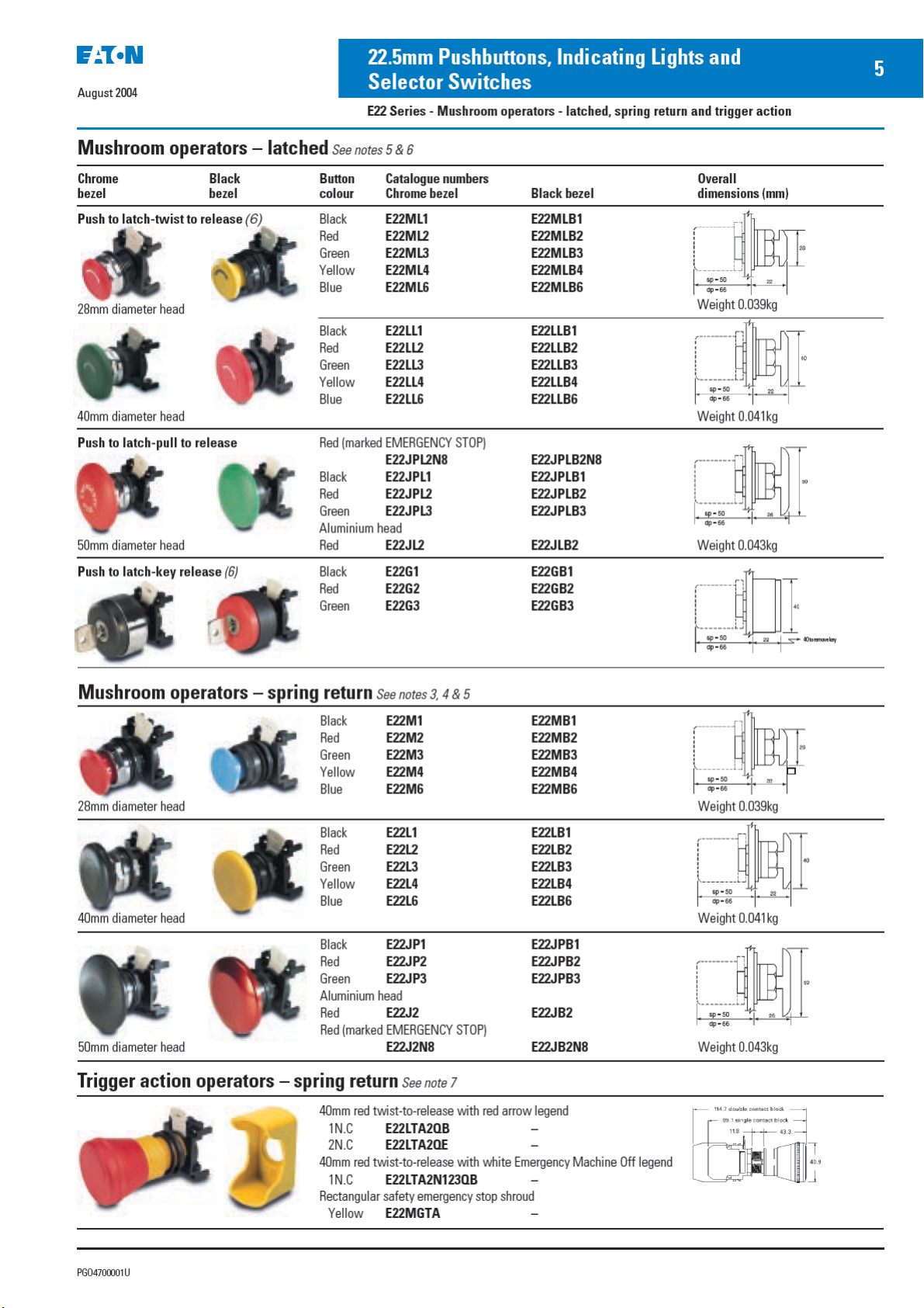
Page 2

Contents
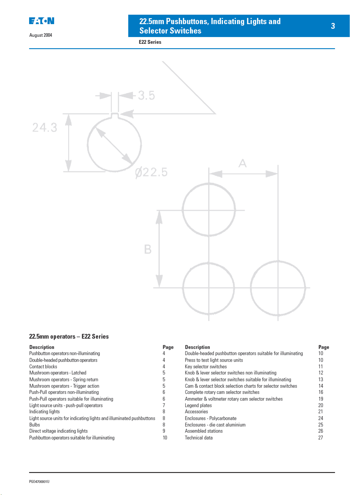
22.5mm operators – E22 Series
Description Page
Pushbutton operators non-illuminating 4
Double-headed pushbutton operators 4
Contact blocks 4
Mushroom operators - Latched 5
Mushroom operators - Spring return 5
Mushroom operators - Trigger action 5
Push-Pull operators non-illuminating 6
Push-Pull operators suitable for illuminating 6
Light source units - push-pull operators 7
Indicating lights 8
Light source units for indicating lights and illuminated pushbuttons 8
Bulbs 8
Direct voltage indicating lights 9
Pushbutton operators suitable for illuminating 10
30.5mm operators – 91000T Series
Description Page
Double-headed pushbutton operators suitable for illuminating 10
Press to test light source units 10
Key selector switches 11
Knob & lever selector switches non illuminating 12
Knob & lever selector switches suitable for illuminating 13
Cam & contact block selection charts for selector switches 14
Complete rotary cam selector switches 16
Ammeter & voltmeter rotary cam selector switches 19
Legend plates 20
Accessories 21
Enclosures - Polycarbonate 24
Enclosures - die cast aluminium 25
Assembled stations 26
Technical data 27
Description Page
Pushbutton operators 32
Mechanical push operators 32
Illuminated pushbuttons 33
Cylinder lock pushbuttons 33
Contact blocks 33
Knob or lever operated selector switches 34
Key operated selector switches 35
Standard indicating lights 36
Prestest Indicating lights 37
Stacklights – E26 Series
Description Page
Product description 48
Catalogue number selection guide 48
Light and xenon strobe modules 49
Accessories 50
LEDs - Cluster or cylindrical 53
Description Page
Roto-push pushbuttons 38
Joystick controllers 39
Legend plates 40
Accessories 41
Assembled pushbutton stations 43
Emergency stop stations 43
Aluminium alloy enclosures 44
Technical data 45
Description Page
Technical data 54
Application data 54
Mounting options and dimensions 55
Dimensions 56
Page 3
August 2004
Pushbuttons, Indicating Lights, Selector
Switches & Stacklights
Contents
1
E22 Series – pages 3-30
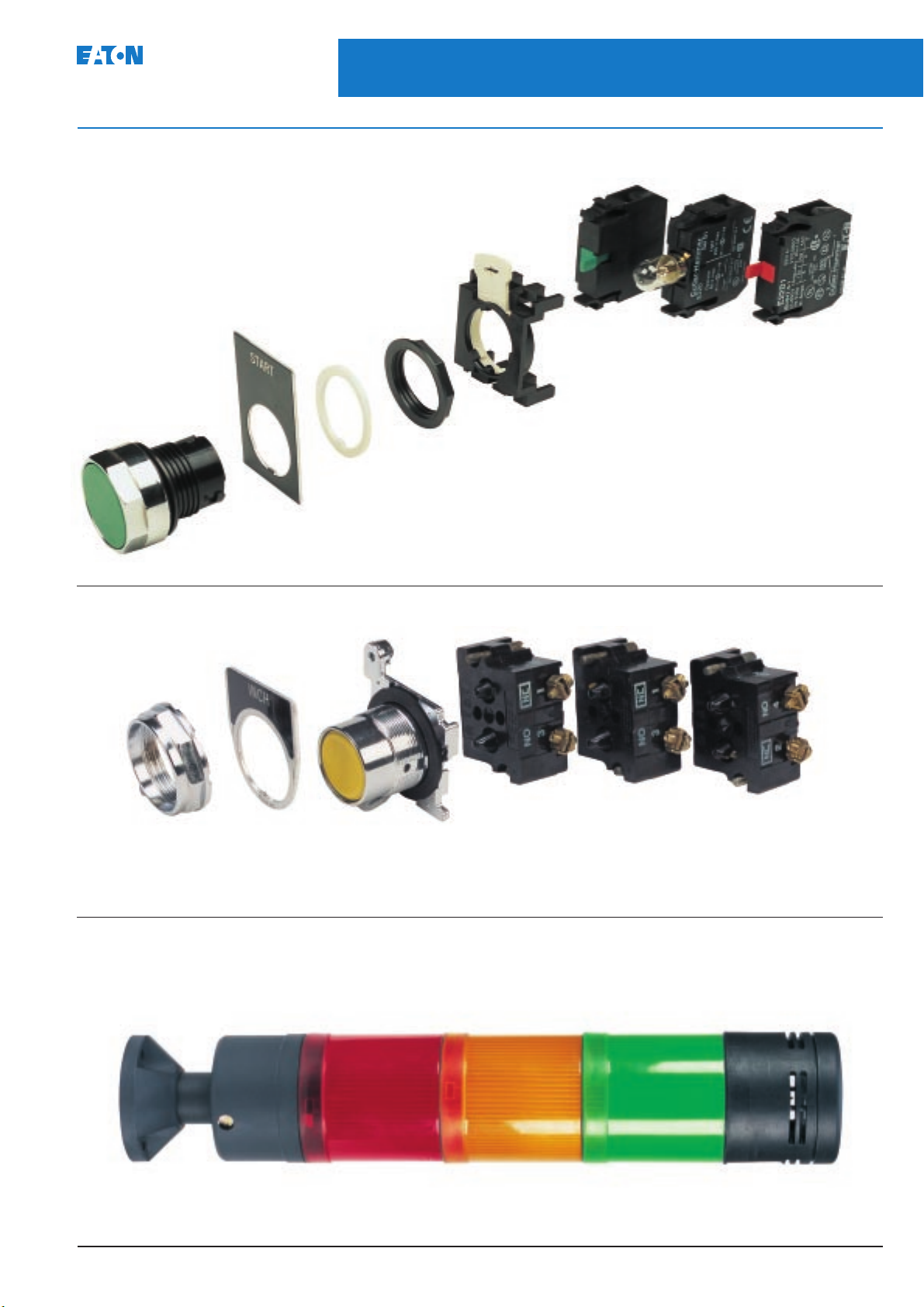
Legend plates,
three styles
available
Bezel,
choice of
chrome or
matt black
Optional
anti-rotation
ring
E22LRP
3-way mounting
adapter E22BA1
Octagonal mounting nut
which eliminates spacer washers
and set screws
Terminal clamps are shipped open,
BA9 bayonet base
lamps used
throughout
ready to wire
Light units and contact
blocks secured to
mounting adapter
without tools
91000T Series – pages 31-45
Mounting
nut
E26 Series – pages 47-56
Mounting
base
Legend
plate
Stacklight
base
Operator
Level
2
Stackable contact blocks
up to 12 circuits per operator
Alarm
PGO4700001U
Extension
tube
Level
1
Level
3
Page 4
Page 5
4
22.5mm Pushbuttons, Indicating Lights and
Selector Switches
August 2004
E22 Series - Non-illuminating operators, double-headed operators and contact blocks
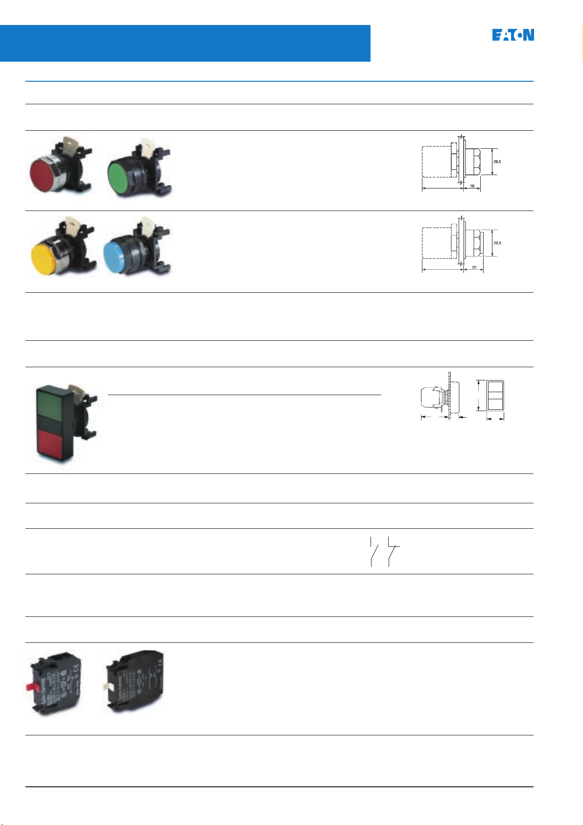
Pushbutton operators non-illuminating
See notes 3,4 & 5
Chrome Black Button Catalogue numbers Overall
bezel bezel colour Chrome bezel Black bezel dimensions (mm)
Flush Black E22P1 E22PB1
Red E22P2 E22PB2
Green E22P3 E22PB3
Yellow E22P4 E22PB4
25mm diameter push
White E22P5 E22PB5
Blue E22P6 E22PB6
Grey E22P7 E22PB7 Weight 0.043kg
sp = 50
dp = 66
Extended Black E22E1 E22EB1
Red E22E2 E22EB2
Green E22E3 E22EB3
Yellow E22E4 E22EB4
25mm diameter push
White E22E5 E22EB5
Blue E22E6 E22EB6
Grey E22E7 E22EB7 Weight 0.043kg
sp = 50
dp = 66
Full shroud bezel operator Add the letter F to the flush button catalogue number eg E22PF1
Double headed pushbutton operators
See note 6
Description Colour of Marking Ingress Catalogue numbers Overall
operators protection Black bezel dimensions (mm)
2 Flush buttons Green - Red Unmarked IP40 E22DB1A11
IP65 E22DB1B11
Green - Red I IP40 E22DB1A21
50
O IP65 E22DB1B21
12
57
28
Assembled operators
Description Colour of Marking Ingress Contact block/ Operator Circuit Catalogue numbers
operators protection light unit black bezel diagram Black bezel
2 Flush buttons Green I IP40 E22B2 E22DB1A21 E22DB1A21C
13 21
Red O E22B1
IP65 E22DB1B21C
14 22
Contact blocks
Description Catalogue numbers Weight
Screw terminals Push-on terminals (kg)
1N.C. E22B1 E22BF1 0.013
1N.O. E22B2 E22BF2 0.013
1N.O. - 1N.C. E22B11 E22BF11 0.022
2N.O. E22B20 E22BF20 0.022
1N.O. early make E22B3 E22BF3 0.013
1N.C. late break E22B4* E22BF4* 0.013
1N.C. low power E22B1E – 0.013
Single pole Double pole
* Cannot be used with 5 way adaptor
Notes:
3. Mounting adaptor for 3 contact blocks included.
4. Use operator plug E22BA2 to operate centre contact block.
5. For printed operators see page 9
1N.O. low power E22B2E – 0.013
6. Only 2 contact blocks can be fitted.
7. See page 30 for technical information
PGO4700001U
Page 6
Page 7
Page 8
August 2004
22.5mm Pushbuttons, Indicating Lights and
Selector Switches
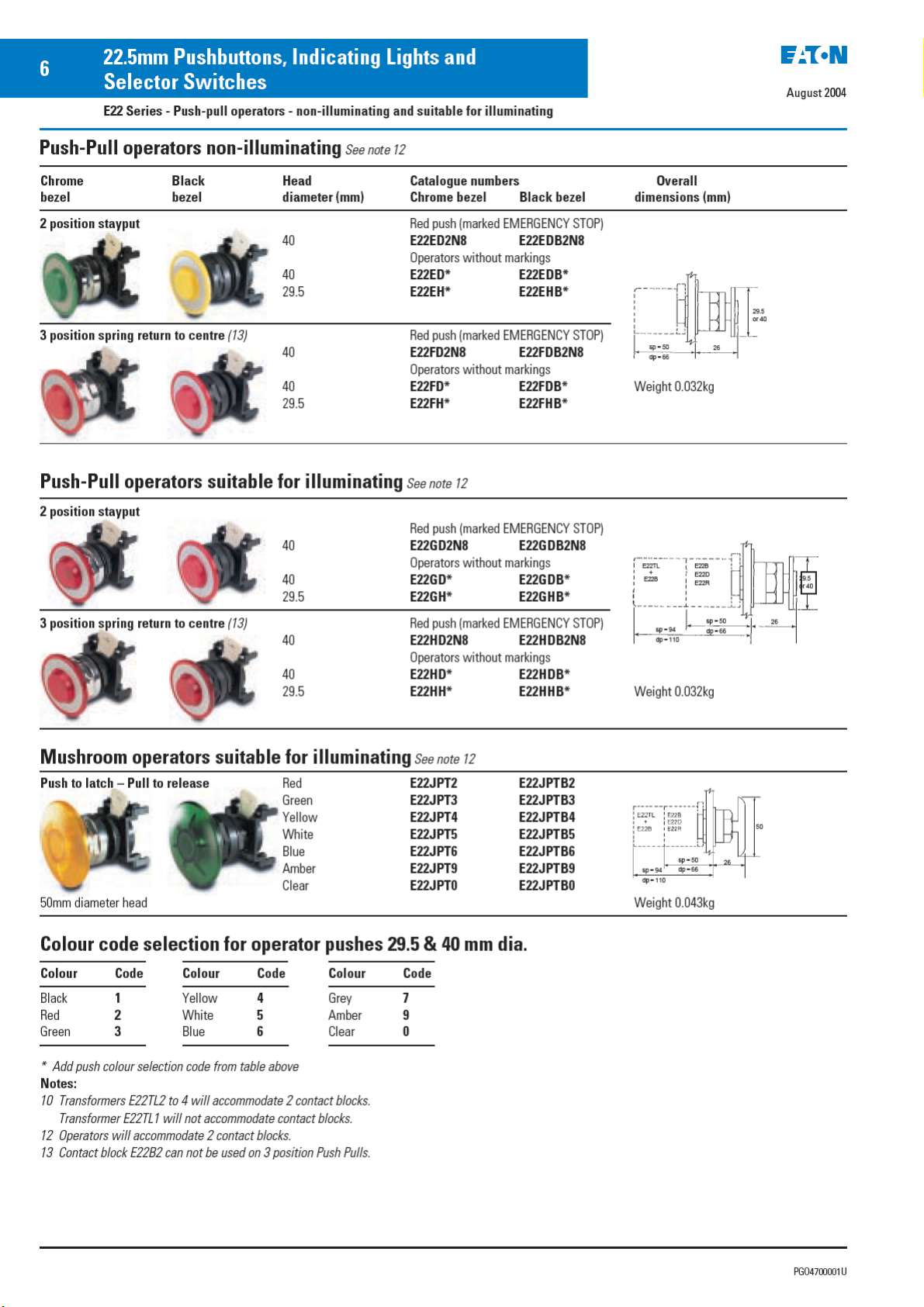
E22 Series - Push-pull operators - light source units
7
Light source units – push-pull operators
Description Supply voltage Catalogue Overall Weight
Transformer
6V secondary 240 240 E22TL2 0.08
Resistor unit 110/120V E22R2 0.018
Direct voltage 6.3V (1W) E22D6 0.018
Bulbs For use with E22D above. See page 8 for LED type bulbs.
Description Operating Catalogue Operating Catalogue
Type BA9s 6 (1W) flasher 28-2225-26 24 (1.2W) 28-2225-30
bayonet 6.3 (1W) 28-2225-72 50 (1W) 28-2225-31
bulb 12 (1.2W) 28-2225-29 60 (1.2W) 28-2225-32
50Hz 60Hz numbers dimensions (mm) (kg)
(10)
110 120 E22TL1 0.08
380/415 – E22TL3 0.08
440 480 E22TL4 0.08
60V bulb
12V (1.2W) E22D12 0.018
24V (1.2W) E22D24 0.018
50V (1W) E22D50 0.018
60V (1.2W) E22D60 0.018
Without bulb E22D 0.018
voltage numbers voltage numbers
BA9s bayonet fitting. Bulb supplied with unit
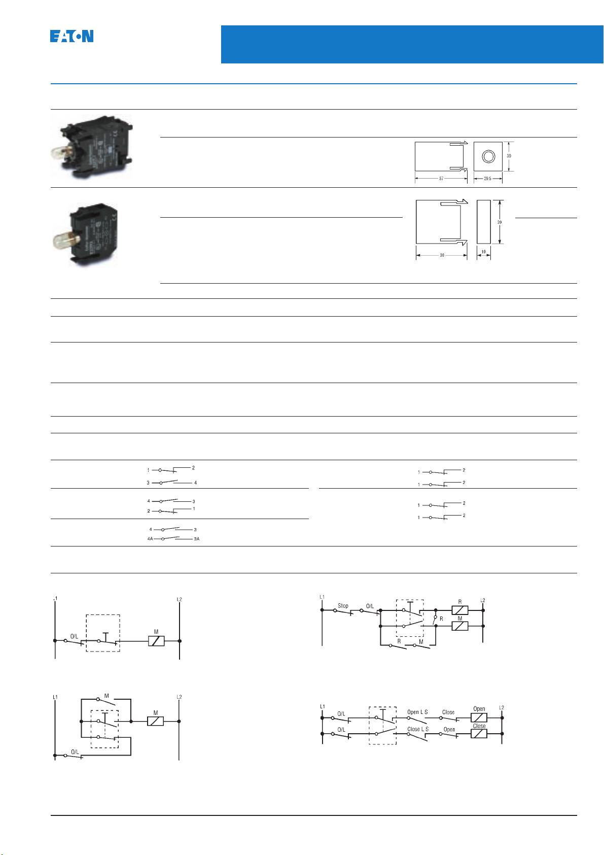
Contact block selection chart
O = circuit open X = circuit closed
2 position push-pull Circuit Catalogue 3 position push-pull Circuit Catalogue
Pulled Pushed numbers Pulled Centre Pushed numbers
XO E22B1 XOO E22B1
OX E22B2 XXO E22B4
OX E22B11 XOO E22B1
OX OOX E22B5
OX E22B20
OX
Typical push-pull applications
2 position push-pull with E22B1 3 position push-pull with E22B1 & E22B5
Pull to start
Push to stop
3 position push-pull with E22B1 & E22B4 3 position push-pull with E22B1 & E22B5
See note 13
BA9s bayonet fitting. Bulb supplied with unit
Pull to run
Push to inch
PGO4700001U
Pull to run
Push to stop
Pull to open
Push to close
Page 9
8
22.5mm Pushbuttons, Indicating Lights and
Selector Switches
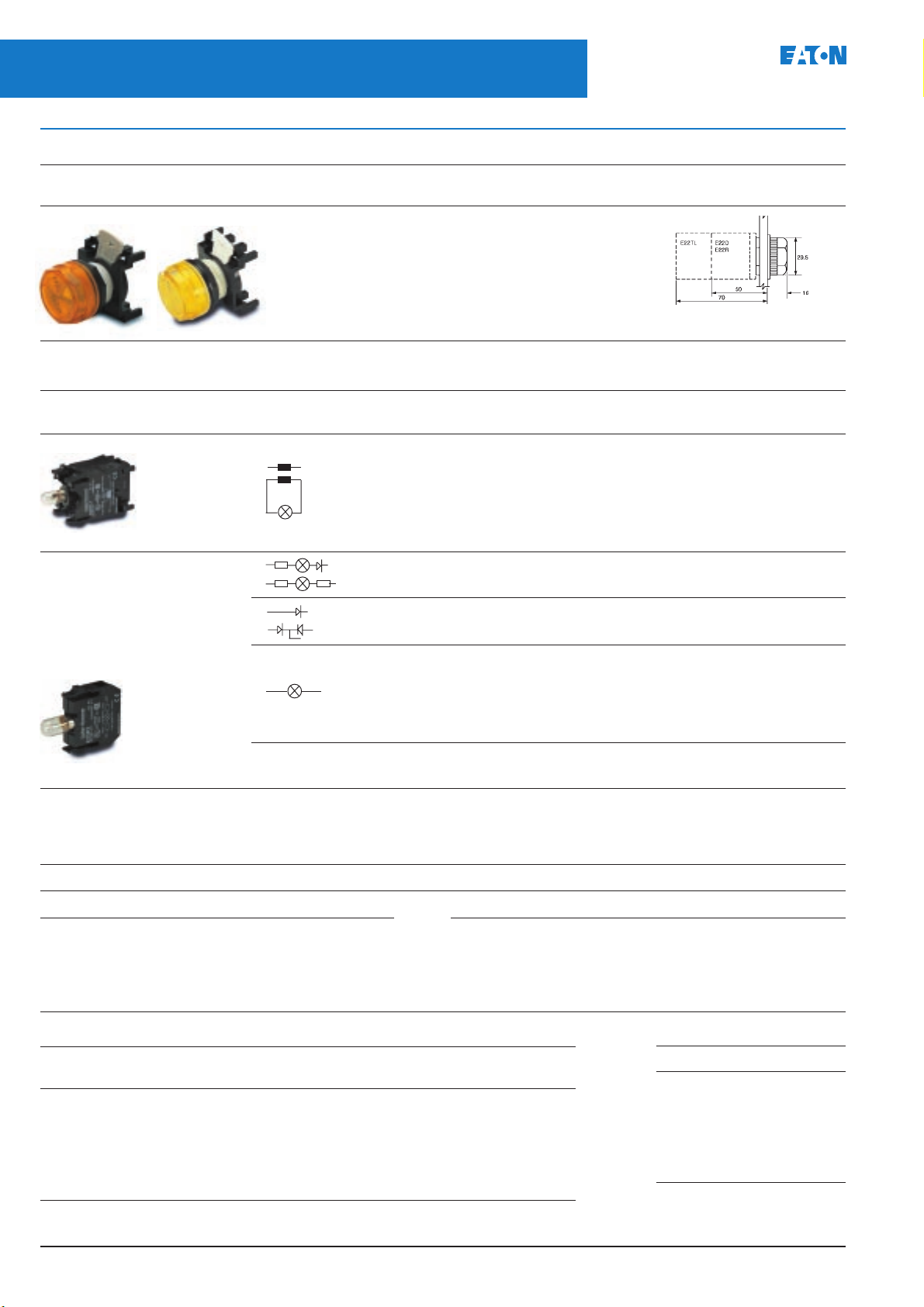
E22 Series - Indicating lights, light sources and bulbs
Indicating lights with plastic lens
Description Lens Catalogue numbers Overall
colour Standard lens Lens suitable for printing
Standard Printable Red E22H2 E22A2
Green E22H3 E22A3
Yellow E22H4 E22A4
White E22H5 E22A5
Blue E22H6 E22A6
Amber E22H9 E22A9
Clear E22H0 E22A0 Weight 0.023kg
(7)
dimensions (mm)
August 2004
Light source units
BA9s bayonet fitting. Bulb supplied with unit.
Description Circuit Supply voltage Catalogue numbers Weight
Operator unit diagram 50Hz 60Hz (kg)
Transformer
(10)
X1
X2
110 120 E22TL1 0.08
240 220 E22TL2 0.08
380/415 – E22TL3 0.08
440 480 E22TL4 0.08
6V secondary
Resistor/Diode (110V bulb)
(8)
Resistor unit (60V bulb) 110/120ac E22R2 0.018
Single diode unit 6 – 120dc E22D1 0.018
Double diode unit 6 – 120dc E22D2 0.018
X1
X1
X5
X5
X2
X1
220/240ac E22R1 0.018
X2
Direct voltage 6Vdc (1W) E22D6 0.018
X1
X2
12Vdc (1.2W) E22D12 0.018
24Vdc (1.2W) E22D24 0.018
50Vdc (1W) E22D50 0.018
110Vdc (2.2W) (8) E22D110 0.018
Without bulb E22D 0.018
For operator light source units with push-on terminals add the letter F to the light source catalogue number eg E22TLF1
Bulbs
Filament and Neon type bulbs For use with E22D and E22R above.
Description Operating voltage Catalogue numbers
Filament 6V (1W) flasher 28-2225-26
type 6.3V (1W) 28-2225-72
12V (1.2W) 28-2225-29
24V (1.2W) 28-2225-30
28V (1.12W) 28-2225-73
LED bulbs
Colour Catalogue numbers
Upto 60Vac/dc 120Vac 120Vdc 135Vac/dc
Blue E22LED*BN E22LED120BA E22LED120BD E22LED135BD
Green E22LED*GN E22LED120GA E22LED120GD E22LED135GD
Orange E22LED*ON E22LED120OA E22LED120OD E22LED135OD
Red E22LED*RN E22LED120RA E22LED120RD E22LED135RD
White E22LED*WN E22LED120WA - E22LED135WD
Yellow E22LED*YN E22LED120YA E22LED120YD E22LED135YD
*Add voltage code alongside to complete catalogue number
Description Operating voltage Catalogue numbers
50V (1W) 28-2225-31
60V (1.2W) 28-2225-32
110V (2.2W) (8) 28-2225-24
Neon type 110V (0.8mA) 28-2225-48
240V (1.5mA) 28-2225-49
Voltage code
Voltage Code
10Vac – 6Vdc 006
12Vac – 12Vdc 012
24Vac – 24Vdc 024
35Vac – 35Vdc 035
48Vac – 48Vdc 048
60Vac – 60Vdc 060
PGO4700001U
Page 10
22.5mm Pushbuttons, Indicating Lights and
August 2004
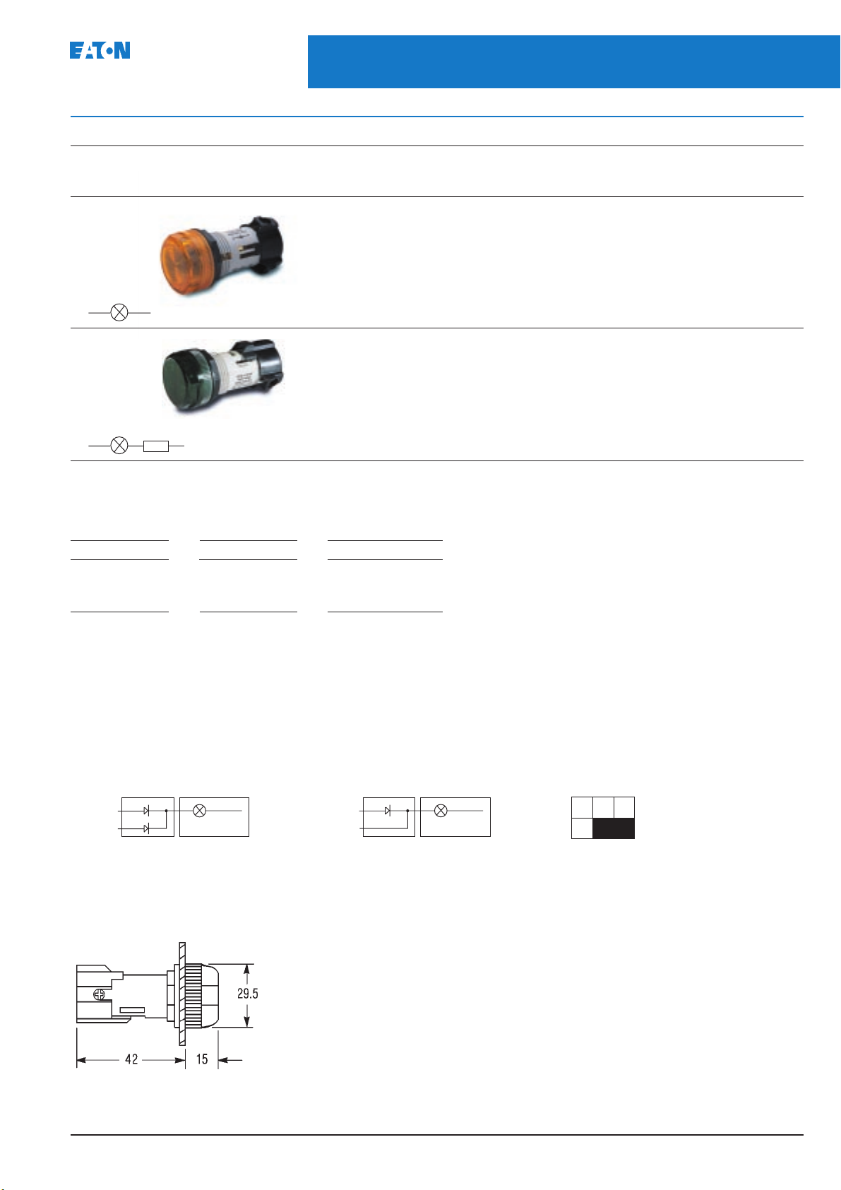
Direct voltage type – bulb not included (order bulb separately)
Description Supply voltage/ Lens Catalogue numbers
Direct voltage 6 - 130V No lens (2) E22HVP E22HV E22HVP E22HV
without resistor (2.6W max.) Red E22HVP2 E22HV2 E22HVR2 E22HVA2
(Excludes bulb) (Not suitable for Green E22HVP3 E22HV3 E22HVR3 E22HVA3
X1 X2
Direct voltage 220/240V input No lens (2) E22HRP E22HR E22HRP E22HR
with built-in 110V output Red E22HRP2 E22HR2 E22HRR2 E22HRA2
resistor (2.6W max.) Green E22HRP3 E22HR3 E22HRR3 E22HRA3
(Excludes bulb) Use filament Yellow E22HRP4 E22HR4 E22HRR4 E22HRA4
X1
X2
Selector Switches
E22 Series - Direct voltage indicating lights
wattage colour Standard lens Lens with printable insert
IP40 IP65 IP40 IP65
240V bulb.) Yellow E22HVP4 E22HV4 E22HVR4 E22HVA4
White E22HVP5 E22HV5 E22HVR5 E22HVA5
Blue E22HVP6 E22HV6 E22HVR6 E22HVA6
Amber E22HVP9 E22HV9 E22HVR9 E22HVA9
Clear E22HVP0 E22HV0 E22HVR0 E22HVA0
bulb only White E22HRP5 E22HR5 E22HRR5 E22HRA5
Blue E22HRP6 E22HR6 E22HRR6 E22HRA6
Amber E22HRP9 E22HR9 E22HRR9 E22HRA9
Clear E22HRP0 E22HR0 E22HRR0 E22HRA0
9
Printed legends for operators and indicating lights
Add the following suffix code to the selected catalogue number. For legends not listed please refer to Eaton.
Legend Suffix
Close N11
Open N26
Power on N80
Notes:
Legend Suffix
Off N24
On N25
Supply on N61
Legend Suffix
Motor running N56
Motor stopped N57
2 Order lens and/or insert separately. See page 23
7 For printed inserts see page 23
8 For use with indicating lights only
10 Transformers E22TL2 to 4 will accommodate 2 contact blocks.
Transformer E22TL1 does not accomodate contact blocks.
Light source unit master test applications
Test X5
Signal X1
E22D2 E22D1 E22DE22D
X2X1
Common
Test X5
Signal X1
X2X1
Common
Mounting position for light source units
132
Dimensions (mm)
Weight: 0.022kg
PGO4700001U
Page 11
10
22.5mm Pushbuttons, Indicating Lights and
Selector Switches
E22 Series - Operators suitable for illuminating and press to test light source units
August 2004
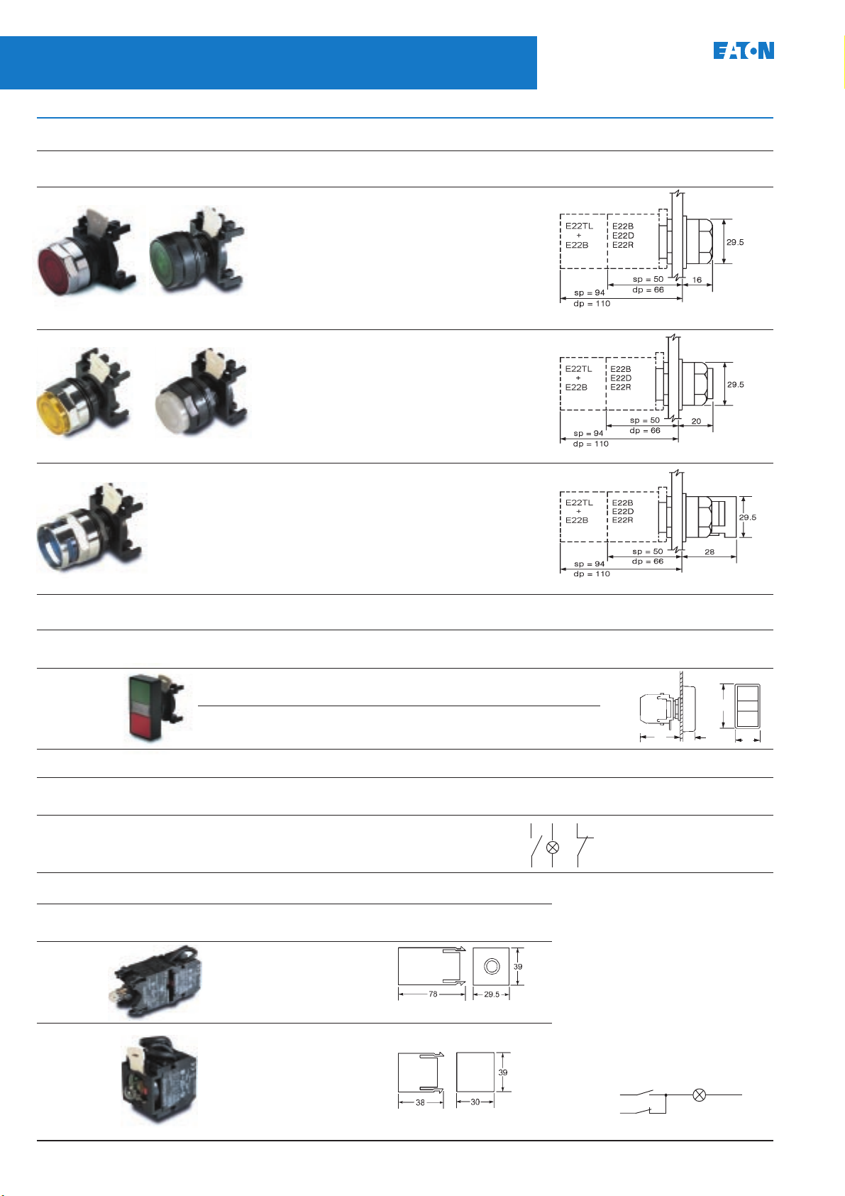
Pushbutton operators suitable for illuminating
See notes 7, 9 & 11
Chrome Black Lens Catalogue numbers Overall
bezel bezel colour Chrome bezel Black bezel dimensions (mm)
Flush button Red E22N2 E22NB2
Green E22N3 E22NB3
Yellow E22N4 E22NB4
White E22N5 E22NB5
Blue E22N6 E22NB6
Amber E22N9 E22NB9
Clear E22N0 E22NB0
25mm diameter push Weight 0.043kg
Extended button Red E22T2 E22TB2
Green E22T3 E22TB3
Yellow E22T4 E22TB4
White E22T5 E22TB5
Blue E22T6 E22TB6
Amber E22T9 E22TB9
Clear E22T0 E22TB0
25mm diameter push Weight 0.043kg
Full shroud Red E22TX2 –
Green E22TX3 –
Yellow E22TX4 –
White E22TX5 –
Blue E22TX6 –
Amber E22TX9 –
Clear E22TX0 –
25mm diameter push Weight 0.045kg
Double headed pushbutton operators
See note 6
Description Colour of Marking Ingress Catalogue numbers Overall
operators protection Black bezel dimensions (mm)
2 Flush buttons Green - Red Unmarked IP40 E22DB1A10
& 1 pilot light IP65 E22DB1B10
with clear lens
Green - Red I IP40 E22DB1A20
O IP65 E22DB1B20
50
12
Assembled operators
Description Colour of Marking Ingress Contact block/ Operator Circuit Catalogue numbers
operators protection light unit black bezel diagram Black bezel
2 Flush buttons Green I IP40 E22B2 E22DB1A20 E22DB1A20X1C
& 1 pilot light Red O E22B1
with clear lens IP65 E22D E22DB1B20X1C
Press to test light source units
For use with illuminated operators
Description Supply voltage Catalogue Overall
50Hz 60HZ numbers dimensions (mm)
Transformer 110 120 E22TL1C
6V filament 240 220 E22TL2C
bulb supplied
6V secondary
Weight 0.106kg
Resistor unit
60V filament 110/120V E22R2C
bulb supplied
Direct voltage 12V E22D12C
Filament bulb 24V E22D24C
supplied 50V E22D50C
Weight 0.044kg
2113 X1
2214 X2
Contact blocks
A light source unit ordered from the
table alongside comes complete with
1N.O. & 1N.C. contact blocks.
If the pushbutton is required to be used
without a light source unit, select the
contact blocks from page 4.
Press to test circuit diagram
24
23
L1
Signal
11
12
57
28
X2X1
Common
PGO4700001U
Page 12
August 2004
22.5mm Pushbuttons, Indicating Lights and
Selector Switches
E22 Series - Key selector switches
11
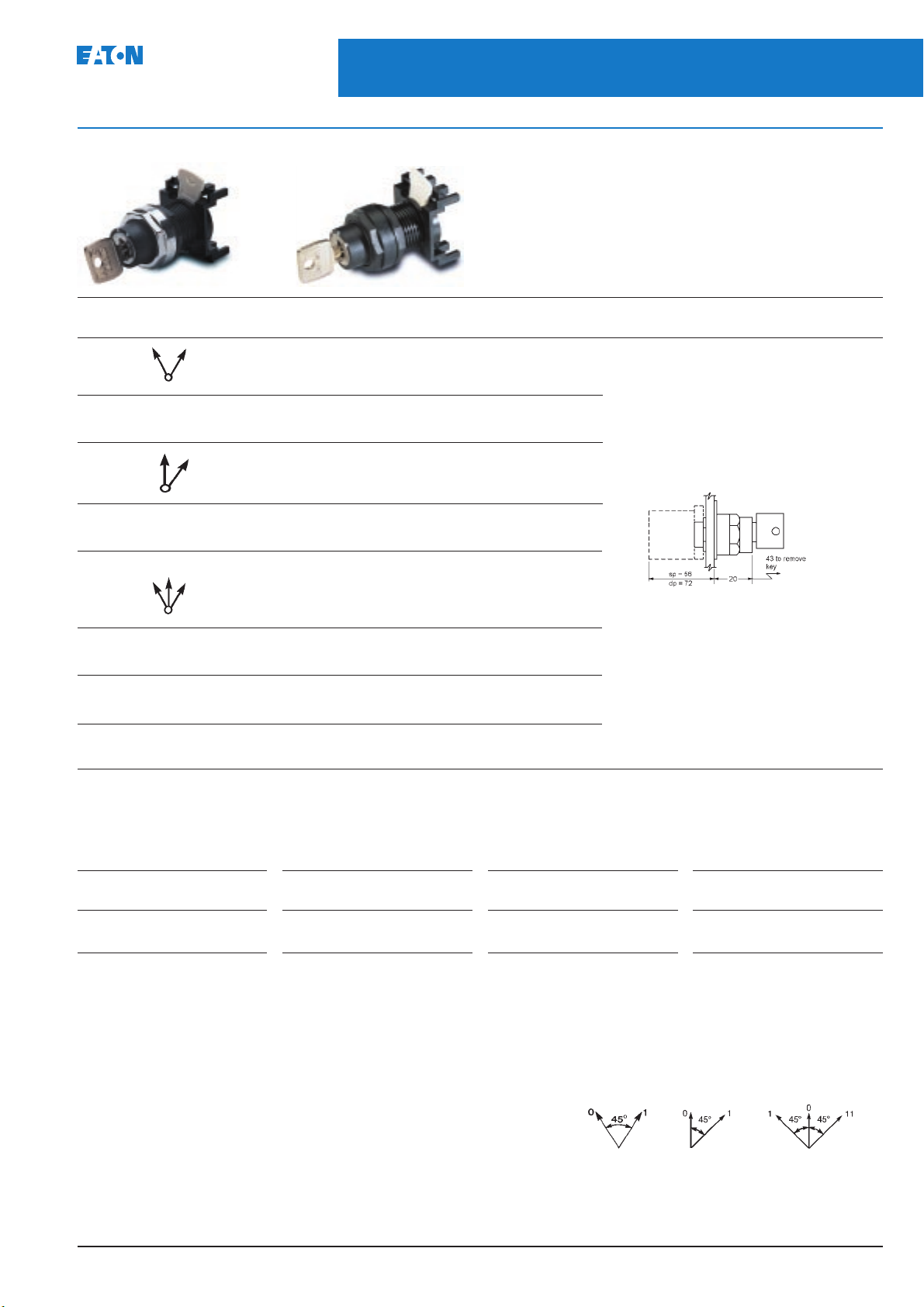
Key selector switches
Chrome bezel Black bezel
Description Key removal Cam Catalogue numbers Overall
2 Position
Stayput Right & left 2 E22K53 E22KB53
Spring return from
right to left Left only 2 E22K62 E22KB62
2 Position
Stayput Centre & right 2 E22KF5 E22KBF5
Spring return from
right to centre Centre 2 E22KE4 E22KBE4
3 Position
Stayput Left, centre 1 E22KG7 E22KBG7
& right 2 E22KH7 E22KBH7 Weight 0.055kg
See note 14
position number Chrome bezel Black bezel dimensions (mm)
Spring return from Centre & 1 E22KJ5 E22KBJ5
left to centre right 2 E22KK5 E22KBK5
Spring return from 1 E22KL4 E22KBL4
right and left to centre Centre 2 E22KM4 E22KBM4
Spring return from Left & 1 E22KN6 E22KBN6
right to centre centre 2 E22KP6 E22KBP6
Alternative key removal position selection
To select an alternative key removal position change the last digit of the listed catalogue number with a code from the table below.
e.g. E22KG6 is a 3 position switch with the key removable from left and centre. Key removal in a spring return position is not available.
Key removal Code Key removal Code Key removal Code Key removal Code
position position position position
Right only 1 Right & left 3 Right & centre 5 Right, left
Left only 2 Centre only 4 Left & centre 6 & centre 7
Special lock selection
Key operated devices listed above are supplied with a standard lock and key, ref. no. 92239.
Different locks and keys are available on request.
Notes:
6 Only 2 contact blocks can be fitted.
7 For printed inserts see page 23
9 Operators will accommodate 2 contact blocks and 1 direct unit or 1 transformer
11 For printed operators see page 23
14 For contact block sequences see pages 14 & 15
Selector switch switching angles
PGO4700001U
Page 13
12
22.5mm Pushbuttons, Indicating Lights and
Selector Switches
E22 Series - Knob and lever selector switches non illuminating
August 2004
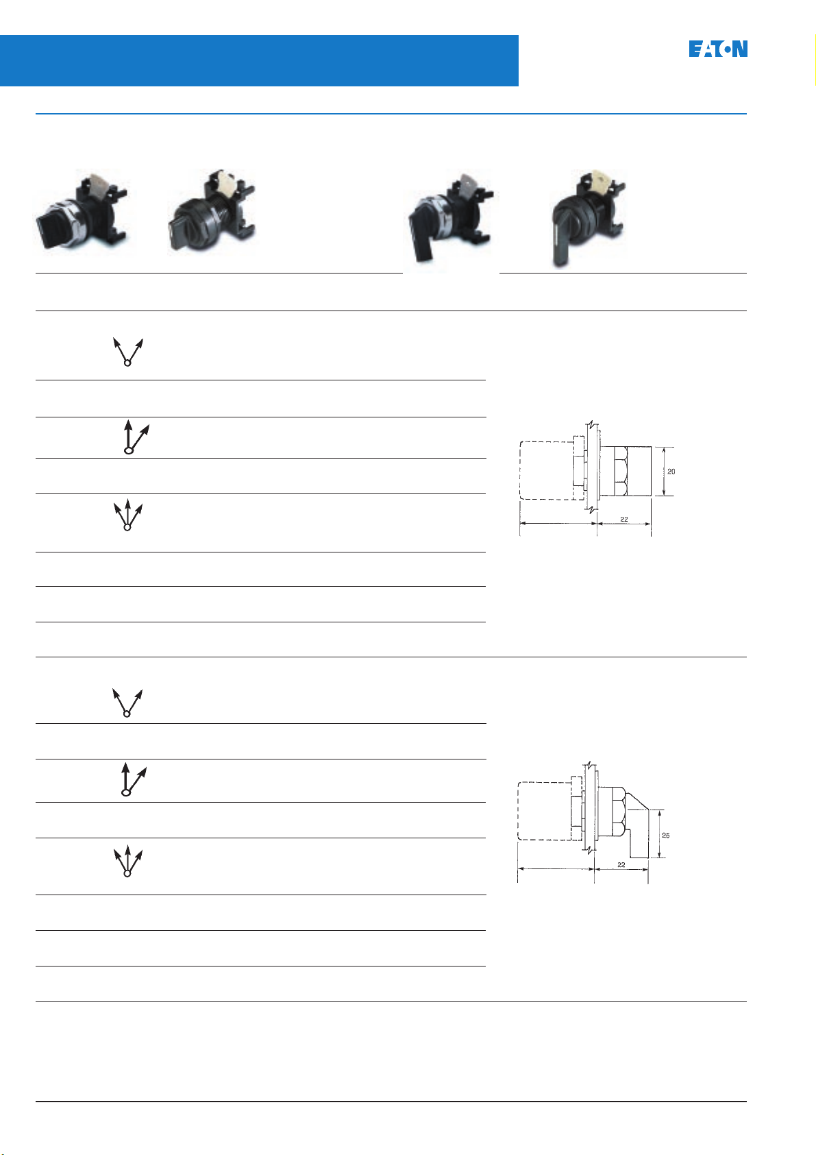
Selector switches non-illuminating
Chrome bezel Black bezel Chrome bezel Black bezel
Description Cam Catalogue numbers Overall
number Chrome bezel Black bezel dimensions (mm)
See note 14
Knob operator Lever operator
Knob selector switch (black)
2 Position
Stayput 2 E22X51 E22XB51
Spring return from
right to left 2 E22X61 E22XB61
2 Position
Stayput 2 E22XF1 E22XBF1
Spring return from
right to centre 2 E22XE1 E22XBE1
3 Position
Stayput 1 E22XG1 E22XBG1
2 E22XH1 E22XBH1
Spring return from 1 E22XJ1 E22XBJ1
left to centre 2 E22XK1 E22XBK1
Spring return from 1 E22XL1 E22XBL1
right and left to centre 2 E22XM1 E22XBM1
Spring return from 1 E22XN1 E22XBN1
right to centre 2 E22XP1 E22XBP1 Weight 0.043kg
sp = 56
dp = 72
Lever selector switch (black)
2 Position
Stayput 2 E22V51 E22VB51
Spring return from
right to left 2 E22V61 E22VB61
2 Position
Stayput 2 E22VF1 E22VBF1
Spring return from
right to centre 2 E22VE1 E22VBE1
3 Position
Stayput 1 E22VG1 E22VBG1
2 E22VH1 E22VBH1
Spring return from 1 E22VJ1 E22VBJ1
left to centre 2 E22VK1 E22VBK1
Spring return from 1 E22VL1 E22VBL1
right and left to centre 2 E22VM1 E22VBM1
Spring return from 1 E22VN1 E22VBN1
right to centre 2 E22VP1 E22VBP1 Weight 0.043kg
Note:
Different colour knobs and levers are available. Please contact Eaton.
sp = 56
dp = 72
PGO4700001U
Page 14
August 2004
22.5mm Pushbuttons, Indicating Lights and
Selector Switches
E22 Series - Knob and lever selector switches suitable for illumination
13
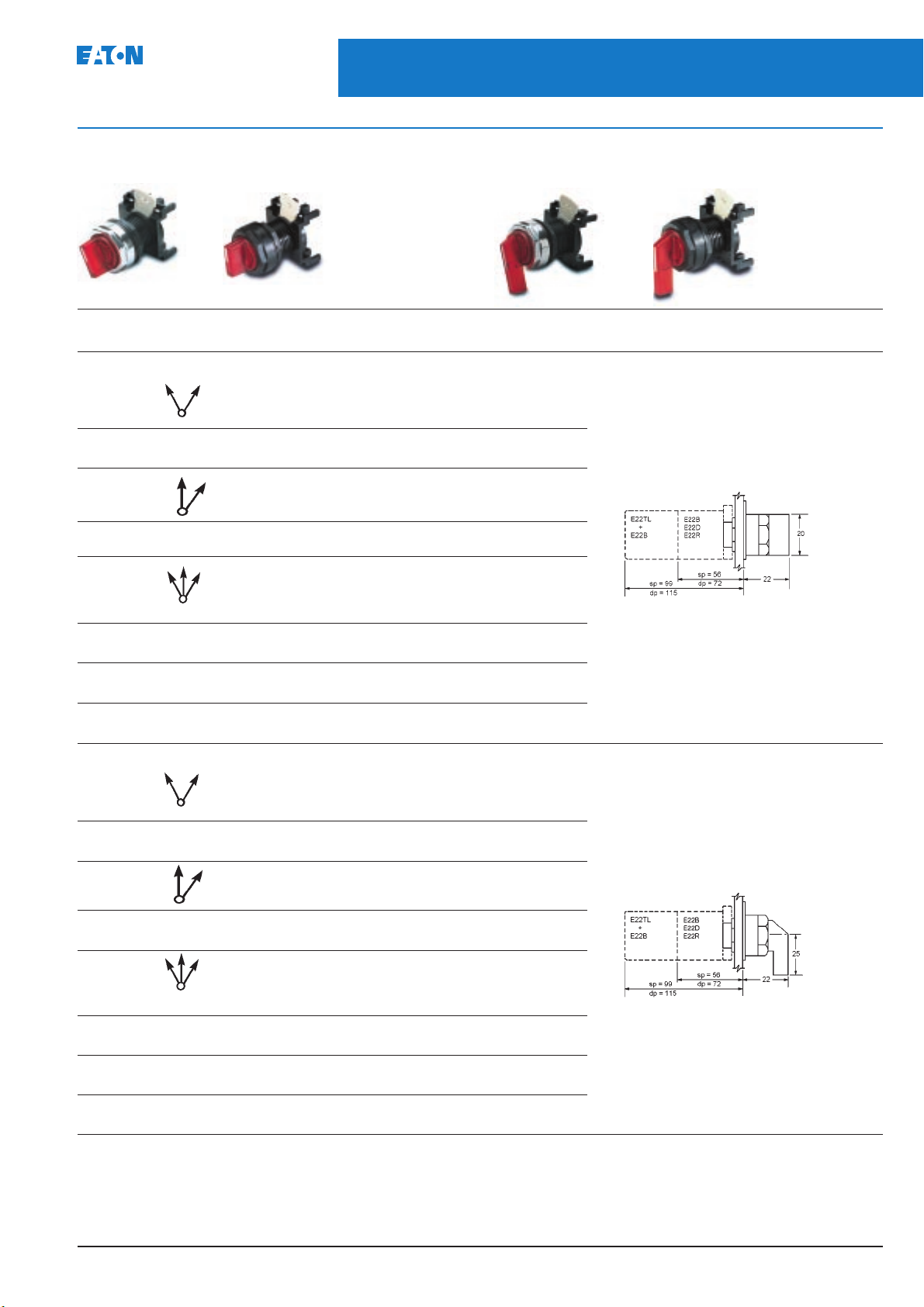
Selector switches suitable for illuminating
Chrome bezel Black bezel Chrome bezel Black bezel
Knob operator Lever operator
Description Cam Catalogue numbers Overall
Knob selector switch (red)
2 Position
Stayput 2 E22S52 E22SB52
Spring return from
right to left 2 E22S62 E22SB62
2 Position
Stayput 2 E22SF2 E22SBF2
Spring return from
right to centre 2 E22SE2 E22SBE2
3 Position
Stayput 1 E22SG2 E22SBG2
Spring return from 1 E22SJ2 E22SBJ2
left to centre 2 E22SK2 E22SBK2
Spring return from 1 E22SL2 E22SBL2
right and left to centre 2 E22SM2 E22SBM2
Spring return from 1 E22SN2 E22SBN2
right to centre 2 E22SP2 E22SBP2 Weight 0.043kg
number Chrome bezel Black bezel dimensions (mm)
(15)
2 E22SH2 E22SBH2
See note 14
Lever selector switch (red)
2 Position
Stayput 2 E22W52 E22WB52
Spring return from
right to left 2 E22W62 E22WB62
2 Position
Stayput 2 E22WF2 E22WBF2
Spring return from
right to centre 2 E22WE2 E22WBE2
3 Position
Stayput 1 E22WG2 E22WBG2
Spring return from 1 E22WJ2 E22WBJ2
left to centre 2 E22WK2 E22WBK2
Spring return from 1 E22WL2 E22WBL2
right and left to centre 2 E22WM2 E22WBM2
Spring return from 1 E22WN2 E22WBN2
right to centre 2 E22WP2 E22WBP2 Weight 0.043kg
Notes:
14 For contact block sequences see pages 14 & 15
15 For light source units see page 8
(15)
2 E22WH2 E22WBH2
PGO4700001U
Page 15
14
22.5mm Pushbuttons, Indicating Lights and
Selector Switches
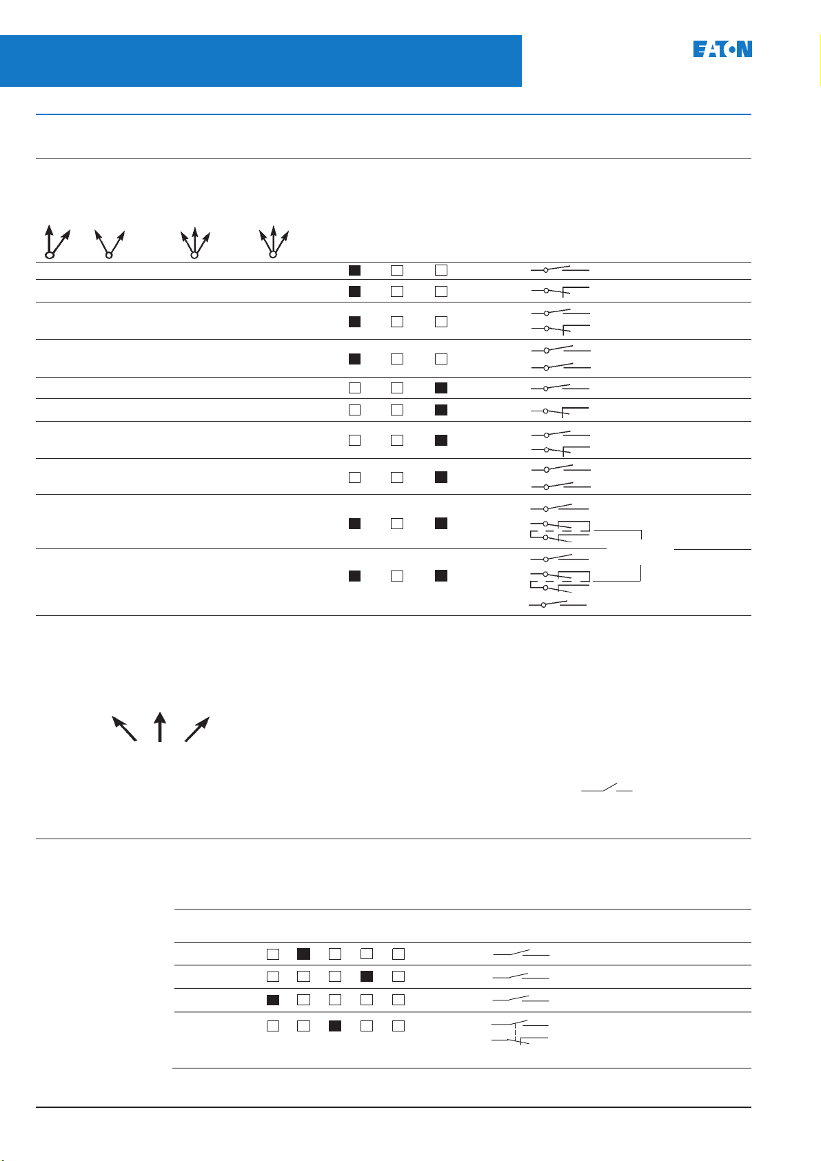
E22 Series - Cam and contact block selection charts for selector switches
August 2004
Cam and contact block selection chart – 3 way adaptor
Circuit configurations. Viewed from front of panel
Contact block
2 position 3 position mounting position. Contact Catalogue
Cam II Cam I Cam II Viewed from rear of panel arrangement number
Left Central Right
or 1 3 2
OX XOO XOX 14 13 E22B2
XO OXX OXO 12 11 E22B1
OX XOO XOX 14 13
XO OXX OXO 12 11 E22B11
OX XOO XOX 14 13
O X X O O X O X 14A 13A E22B20
OX OOX OOX 24 23 E22B2
XO XXO XXO 22 21 E22B1
OX OOX OOX 24 23
XO XXO XXO 22 21 E22B11
OX OOX OOX 24 23
OX OOX OOX 24A 23A E22B20
OX XOO XOX 12 11 E22B11+B1
X O O X O O X O B11 B1 22 21
OX XOO XOX 14 13
XO OXO OXO 12 11 E22B11+B11
O X O O X O O X B11 B11 22 21
See note 16
14 13
External
link
24 23
Explanation of how to use selector switch contact block selection chart
1. Determine the "X O" sequence you require for
your application.
Example:
Hand Off Auto
XOO
OOX
X = Cicuit closed
O = Circuit open
16 Illuminated selector switches will accommodate 1 direct voltage or 1 transformer unit with 2 contact blocks.
Note:
2. Locate the first sequence "X O O" under column
marked Cam I or Cam II, then identify which Cam
and contact is used and in what position it is
assembled.
Example: "X O O" uses Cam I, E22B2, mounting
position 1 (left)
3. Repeat for second sequence "O O X". Do not
mix sequences from Cam I and Cam II.
Example: "O O X" uses Cam I, E22B2, mounting
position 2 (right)
5 Way adaptor mounting example
Requirement
Hand Off Auto
XOO
OOX
XOO
XOO
OXX
Contact Mounting position Contact Contact block
status 5– 1– 3– 2– 4– arrangement catalogue number
X O O 14 13 E22B2
O O X 24 23 E22B2
X O O 34 33 E22B2
X O O 54 53 E22B11
O X X 52 51
With contact block printing facing position 2
The above example uses a 3 position selector switch cam 1 plus mounting adaptor E22BA12
″
4. Assemble contact block(s) to adaptor in the
mounting position selected (two contact blocks
per switch), using the selector switch with the
appropriate cam and switch positions. Cam I has
1 peak, Cam II has 2 peaks, viewed from the rear.
Terminal numbers
These identify the contact block position and
contact function.
Example: 14 13.
The "1" indicates mounting position number 1
(left), "3 & 4" indicates the circuit is N.O.
PGO4700001U
Page 16
22.5mm Pushbuttons, Indicating Lights and
August 2004
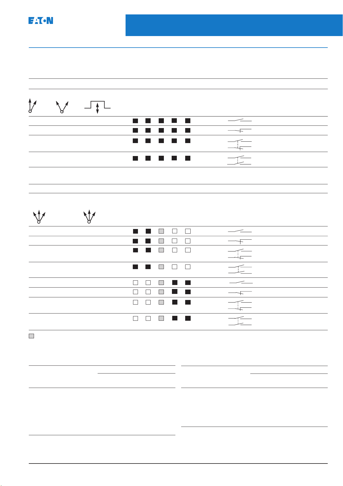
Cam and contact block selection charts – 5 way adaptor
2 position selector switch operators and pushbuttons
Circuit configurations viewed from front of panel
2 postion cam 2 Pushbutton Contact block Contact Contact block
or or 5– 1– 3– 2– 4–
O X –4 –3 E22B2
X O –2 –1 E22B1
O X –4 –3 E22B11
X O –2 –1
O X –4 –3 E22B20
O X –4A –3A
3 position selector switch operators
Circuit configurations viewed from front of panel
3 position 3 position Contact block Contact Contact block
cam l cam 2 mounting position arrangement catalogue
Selector Switches
E22 Series - Cam and contact block selection charts for selector switches
mounting position arrangement catalogue
number
number
15
5– 1– 3– 2– 4–
X O O Not suitable –4 –3 E22B2
O X X " –2 –1 E22B1
X O O " –4 –3 E22B11
A
A
A
O X X " –2 –1
X O O " –4 –3 E22B20
A
X O O " –4A –3A
O O X " –4 –3 E22B2
X X O " –2 –1 E22B1
O O X " –4 –3 E22B11
B
B
B
X X O " –2 –1
O O X " –4 –3 E22B20
B
O O X " –4A –3A
A. Operated as positions 1 & 5 with contact block printing facing position 2. B. Operated as positions 2 & 4 with contact block printing facing position 1.
Applications
Use any combination of contact blocks/light source except where noted
Front of panel device 5 way adaptor/back of panel options
Non ill operators Ill operators
E22BA11 BA12 E22BA11L BA12L
Flush & extended pushbuttons Yes No Yes No
28, 40, 50mm mushroom (momentary) Yes No No No
50mm mushroom latch (pull to release) Yes No Yes No
40mm mushroom latch (key release) Yes ✝ No No No
28 & 40mm mushroom latch
(twist to release) Yes ✝ No No No
29.5 and 40mm 2 position push pull Yes No Yes No
Notes:
E22B4 & E22BF4 can not be used with 5 way adaptors.
5 way adaptors can only be used in single way double contact block depth enclosures.
Front of panel device 5 way adaptor/back of panel options
Non ill operators Ill operators
E22BA11 BA12 E22BA11L BA12L
29.5 and 40mm 3 position push pull No No No No
Double headed pushbutton No No No No
2 position selector switch cam 2 Yes No Yes No
3 position selector switch cam 1 No Yes No Yes
3 position selector switch cam 2 No No No No
✝ 4 single circuit contact blocks maximum
PGO4700001U
Page 17
16
22.5mm Pushbuttons, Indicating Lights and
Selector Switches
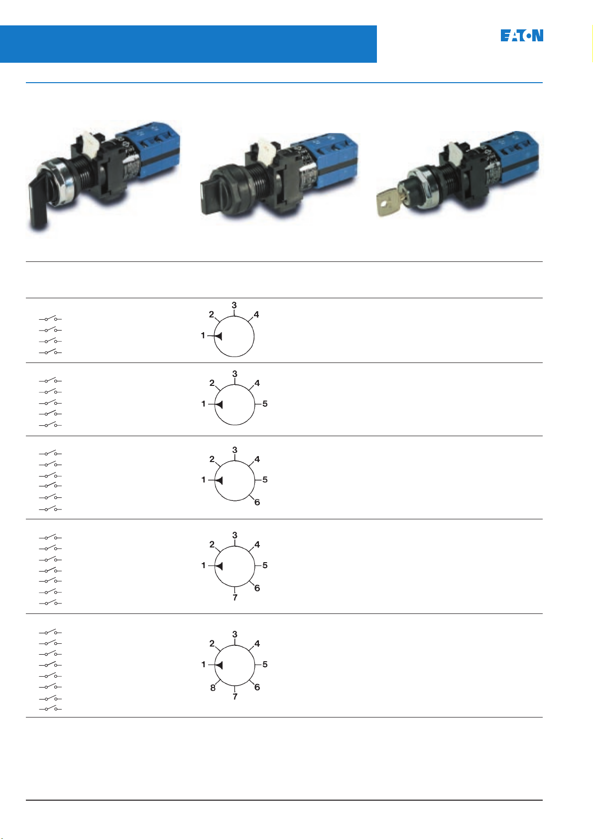
E22 Series - Complete rotary cam selector switches
August 2004
Complete rotary cam selector switches
See notes 17 & 18
Lever operator Knob operator Key operator
Description, Contact Switch Operator Catalogue numbers
circuit and sequence position type Chrome Black
terminal numbers bezel bezel
4 Position 1 2 3 4 Lever E22JD4W1 E22JDB4W1
2
1
5
6
3
4
7
8
X O O O Knob E22LD4W1 E22LDB4W1
O X O O Key E22KD4W8 E22KDB4W8
OOXO
OOOX
5 Position 1 2 3 4 5 Lever E22JD5W1 E22JDB5W1
2
1
7
8
10
9
5
6
3
4
X O O O O Knob E22LD5W1 E22LDB5W1
O X O O O Key E22KD5W8 E22KDB5W8
OOXOO
OOOXO
OOOOX
6 Position 1 2 3 4 5 6 Lever E22JD6W1 E22JDB6W1
2
1
5
6
10
12
9
11
3
4
8
7
X O O O O O Knob E22LD6W1 E22LDB6W1
OXOOOO Key E22KD6W8 E22KDB6W8
OOXOOO
OOOXOO
OOOOXO
OOOOOX
7 Position 1234567 Lever E22JD7W E22JDB7W1
2
1
5
6
10
14
9
13
3
4
8
7
1112
XOOOOOO Knob E22LD7W1 E22LDB7W1
OXOOOOO Key E22KD7W8 E22KDB7W8
OOXOOOO
OOOXOOO
OOOOXOO
OOOOOXO
OOOOOOX
8 Position 12345678 Lever E22JD8W1 E22JDB8W1
2
1
5
6
10
14
9
13
3
4
8
7
1112
1516
XOOOOOOO Knob E22LD8W1 E22LDB8W1
OXOOOOOO Key E22KD8W8 E22KDB8W8
OOXOOOOO
OOOXOOOO
OOOOXOOO
OOOOOXOO
OOOOOOXO
OOOOOOOX
PGO4700001U
Page 18
August 2004
22.5mm Pushbuttons, Indicating Lights and
Selector Switches
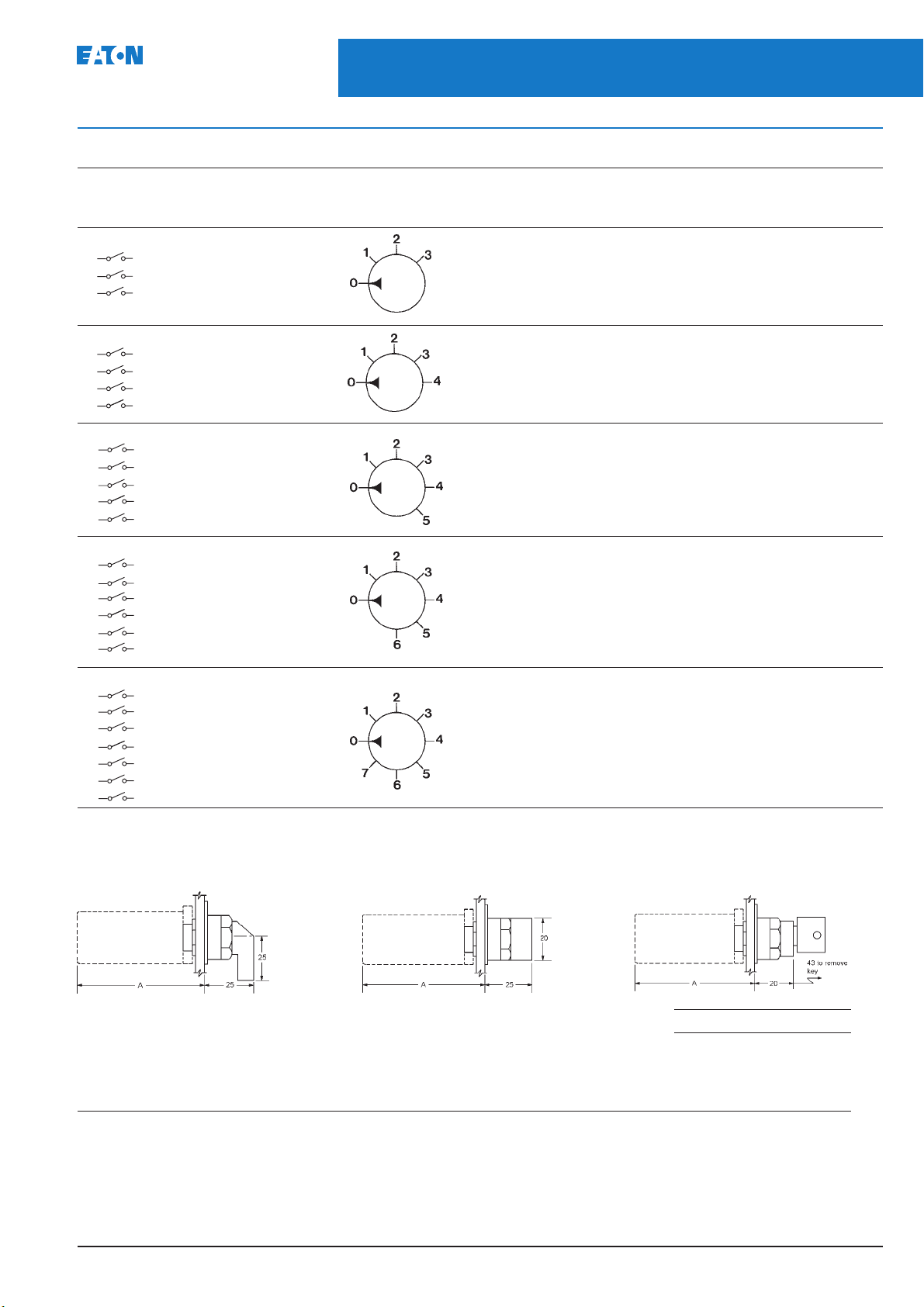
E22 Series - Complete rotary cam selector switches
17
Complete rotary cam selector switches
See notes 17 & 18
Description, Contact Switch Operator Catalogue numbers
circuit and sequence position type Chrome Black
terminal numbers bezel bezel
4 Position 0 1 2 3 Lever E22JD4Y1 E22JDB4Y1
2
1
5
6
3
4
O X O O Knob E22LD4Y1 E22LDB4Y1
O O X O Key E22KD4Y8 E22KDB4Y8
OOOX
5 Position 0 1 2 3 4 Lever E22JD5Y1 E22JDB5Y1
2
1
5
6
3
4
7
8
O X O O O Knob E22LD5Y1 E22LDB5Y1
O O X O O Key E22KD5Y8 E22KDB5Y8
OOOXO
OOOOX
6 Position 0 1 2 3 4 5 Lever E22JD6Y1 E22JDB6Y1
1
2
5
6
7
8
9
10
3
4
O X O O O O Knob E22LD6Y1 E22LDB6Y1
OOXOOO Key E22KD6Y8 E22KDB6Y8
OOOXOO
OOOOXO
OOOOOX
7 Position 0 1 2 3 4 5 6 Lever E22JD7Y1 E22JDB7Y1
2
1
5
6
10
12
9
11
3
4
8
7
O X O O O O O Knob E22LD7Y1 E22LDB7Y1
OOXOOOO Key E22KD7Y8 E22KDB7Y8
OOOXOOO
OOOOXOO
OOOOOXO
OOOOOOX
8 Position 0 1 2 3 4 5 6 7 Lever E22JD8Y1 E22JDB8Y1
2
1
5
6
10
14
9
13
3
4
8
7
1112
O X O O O O O O Knob E22LD8Y1 E22LDB8Y1
OOXOOOOO Key E22KD8Y8 E22KDB8Y8
OOOXOOOO
OOOOXOOO
OOOOOXOO
OOOOOOXO
OOOOOOOX
Dimensions (mm)
Lever operator Knob operator Key operator
No. of circuits Dim. A
1 – 2 72mm
3 – 4 84mm
5 – 6 96mm
7 – 8 108mm
Notes:
17 Lever and knob switches are fitted with black operators.
18 Key switches are fitted with standard lock key ref. 92239 with the key removable in all positions. For a non-standard lock refer to Eaton.
PGO4700001U
Page 19

18
22.5mm Pushbuttons, Indicating Lights and
Selector Switches
E22 Series - Complete rotary cam selector switches
August 2004
Complete rotary cam selector switches
See notes 17 & 18
Lever operator Knob operator Key operator
Description Circuit and Contact Number Operator Catalogue numbers
terminal numbers sequence of poles type Chrome bezel Black bezel
2 Position 1 Lever E22JDP1 E22JDBP1
2
changeover Knob E22LDP1 E22LDBP1
6
10
14
1
3
5
7
9
11
13
15
Pole 1
Pole 2
Pole 3
Pole 4
XO
OX
XO
OX
XO
OX
XO
OX
Key E22KDP5 E22KDBP5
2 Lever E22JDR1 E22JDBR1
Knob E22LDR1 E22LDBR1
Key E22KDR5 E22KDBR5
3 Lever E22JDS1 E22JDBS1
Knob E22LDS1 E22LDBS1
Key E22KDS5 E22KDBS5
4 Lever E22JDT1 E22JDBT1
Knob E22LDT1 E22LDBT1
Key E22KDT5 E22KDBT5
2 Position 1 Lever E22JDP51 E22JDBP51
changeover Knob E22LDP51 E22LDBP51
2
6
10
14
1
3
5
7
9
11
13
15
Pole 1
Pole 2
Pole 3
Pole 4
XO
OX
XO
OX
XO
OX
XO
OX
Key E22KDP53 E22KDBP53
2 Lever E22JDR51 E22JDBR51
Knob E22LDR51 E22LDBR51
Key E22KDR53 E22KDBR53
3 Lever E22JDS51 E22JDBS51
Knob E22LDS51 E22LDBS51
Key E22KDS53 E22KDBS53
4 Lever E22JDT51 E22JDBT51
Knob E22LDT51 E22LDBT51
Key E22KDT53 E22KDBT53
2
3 Position XOO 2 Lever E22JDV1 E22JDBV1
without off OXO Knob E22LDV1 E22LDBV1
3 Position XOO 3 Lever E22JDW1 E22JDBW1
with centre OOX Knob E22LDW1 E22LDBW1
position off
1
Pole 1
5
6
4
3
11
12
7
8
10
2
4
6
8
10
12
Pole 2
9
1
Pole 1
3
5
Pole 2
7
9
Pole 3
11
OOX Key E22KDV7 E22KDBV7
XOO
OXO
OOX
XOO
Key E22KDW7 E22KDBW7
OOX
XOO
OOX
Switching angles
Overall dimensions. See page 19
PGO4700001U
Page 20
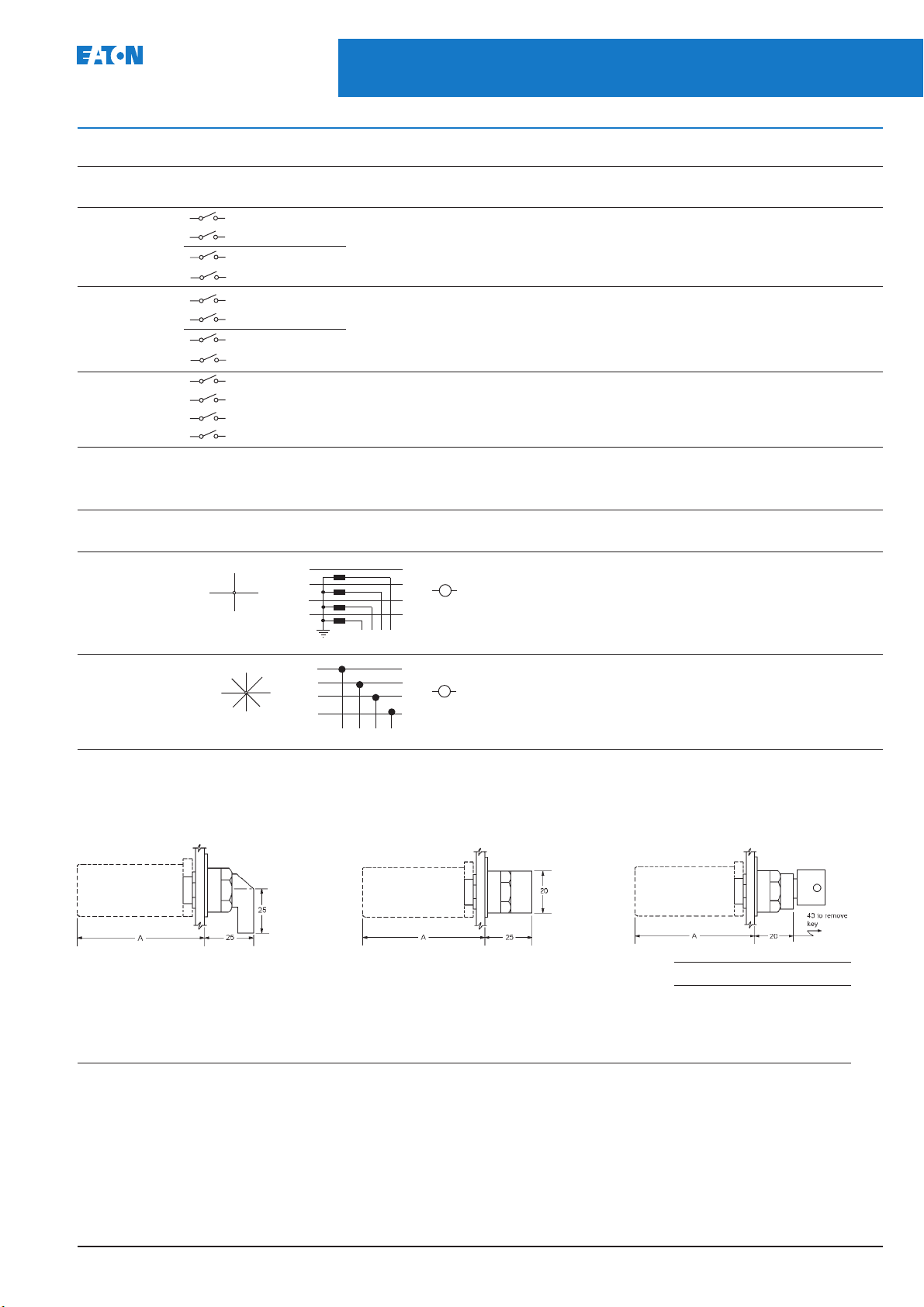
August 2004
22.5mm Pushbuttons, Indicating Lights and
Selector Switches
E22 Series - Ammeter and voltmeter rotary cam selector switches
19
Complete rotary cam selector switches
See notes 17 & 18
Description Circuit and Contact Number Operator Catalogue numbers
terminal numbers sequence of poles type Chrome bezel Black bezel
2
3 Position 2 Lever E22JDL1 E22JDBL1
with right Knob E22LDL1 E22LDBL1
hand position Key E22KDL7 E22KDBL7
off
3 Position 2 Lever E22JDM1 E22JDBM1
with left Knob E22LDM1 E22LDBM1
hand position Key E22KDM7 E22KDBM7
off
4 Position XOOO 1 Lever E22JDN1 E22JDBN1
without off OXOO Knob E22LDN1 E22LDBN1
1
Pole 1
3
4
6
5
Pole 2
7
8
2
1
Pole 1
3
4
6
5
Pole 2
7
8
2
1
5
6
8
4
Pole 1
7
3
XOO
OXO
XOO
OXO
OXO
OOX
OXO
OOX
OOXO
OOOX
Ammeter and voltmeter rotary cam selector switches
Description Switch Circuit and Operator Catalogue numbers
positions terminal numbers type Chrome bezel Black bezel
Ammeter switch
(Single pole Lever E22JDAM1 E22JDBAM1
4 current Knob E22LDAM1 E22LDBAM1
transformers)
L1
NL2
L3
L1 R
L2
L3
N
1
12
410 2
S
1
A
T
O
5
L2-L3
L2-L1
L1-L3
Off
Off
Voltmeter switch
(3 Phase to phase Lever E22JDVM1 E22JDBVM1
and 3 phase to Knob E22LDVM1 E22LDBVM1
neutral)
L1-N
L3-N
L2-N
L1
L2
L3
N
10 6 2 12
R
S
T
O
31
V
Dimensions (mm)
Lever operator Knob operator Key operator
No. of circuits Dim. A
1 – 2 72mm
3 – 4 84mm
5 – 6 96mm
7 – 8 108mm
Notes:
17 Lever and knob switches are fitted with black operators.
18 Key switches are fitted with standard lock key ref. 92239 with the key removable in all positions. For a non-standard lock refer to Eaton.
PGO4700001U
Page 21
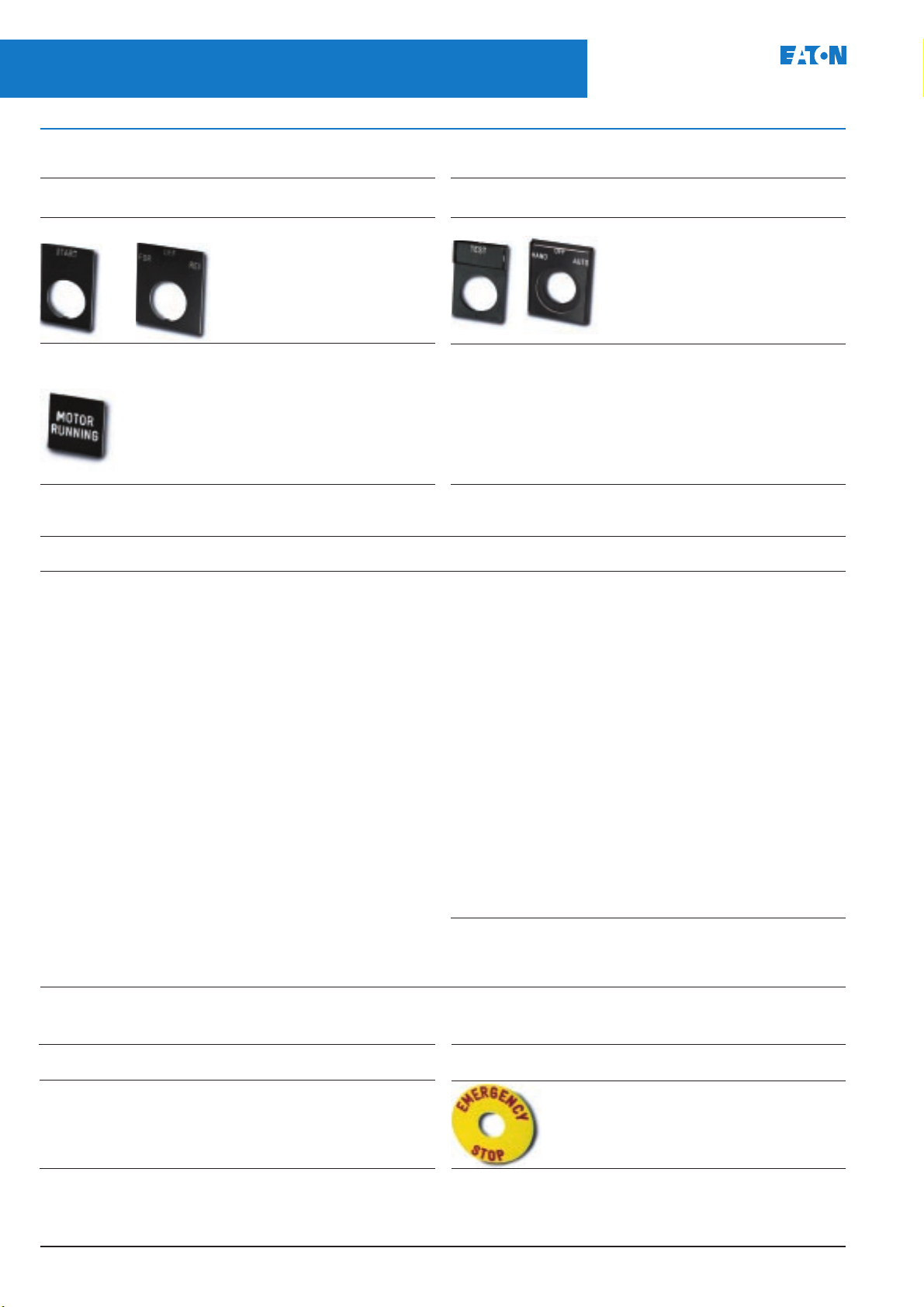
20
22.5mm Pushbuttons, Indicating Lights and
Selector Switches
E22 Series - Legend plates
Legend plates
August 2004
Description Size Catalogue
(mm) numbers
Aluminium (IP65) 30 x 45 E22NE*
40 x 45 E22NF*
Description Size Catalogue
(mm) numbers
Clip-in legend (IP65) 30 x 45 Legend carrier E22ND
40 x 45 Legend carrier E22PD
30 x 45 40 x 45
Enclosure legend plate
(Adhesive backing) 19 x 19 E22NC*
* Add relevent suffix code from list below for required legend. Example E22NE11 = aluminium legend plate engraved “close”.
Legend Code
(Blank) 36
(Blank✝) 37
Auto Off Hand 49
Clamp 90
Close 11
Down 12
Emerg stop✝ 13
Fast 14
For 4
Forward 15
For Off Rev 50
(19)
For Rev
(20)
For Rev
Hand Auto
Hand Auto
Hand Off Auto 51
High 16
High Low
High Low
I 65
I O II 121
In 17
Inch 18
Inch forward 76
(19)
(20)
(19)
(20)
number
38
101
39
102
40
103
Legend Code
Inch reverse 59
Inch Run
(19)
(20)
Inch Run
Jog 19
Jog for 96
Jog rev 21
Left 10
Left Right
Left Right
Loc Rem
Loc Rem
Low 22
Lower 23
Man Auto
Man Auto
Man Off Auto 68
Motor run 81
Motor running 56
Motor stop 82
Motor stopped 57
O✝ 64
O I
O I
Off✝ 24
(19)
(20)
(19)
(20)
(19)
(20)
(19)
(20)
number
60
114
66
117
63
116
67
118
122
120
Special engraving
Where non-standard engraving is required the maximum number of letters
(including spaces) 3mm high that can be engraved per row is as follows:
E22ND 2 rows, 8 letters
E22NE 3 rows, 8 letters
E22NF 3 rows, 11 letters
E22PD 2 rows, 11 letters
Legend Code
Off On
(19)
Off On
(20)
On 25
Open 26
Open Close
Open Close
Open Off Close 53
Out 27
Overload tripped 98
Overload reset 100
Power on 80
Raise 28
Ready 86
Reset 29
Rev 6
Reverse 30
Right 79
Run 31
Seq. Test
Seq. Test
Notes:
(19)
(20)
(19)
(20)
(19) For selector switches with left/right switch angle.
(20) For selector switches with centre/right switch angle.
number
42
105
43
106
62
115
Legend plate E22ND*
Legend plate E22PD*
Legend Code
Slow 32
Slower 88
Start 33
Start Inch
Start Inch
Start Stop
Start Stop
Stop✝ 34
Stop reset✝ 58
Supply on 61
Test 83
Trip 84
Unclamp 91
Up Down
Up Down
Up 35
Special legend 36x
Special legend✝ 37x
Quote legend required.
(19)
(20)
(19)
(20)
(19)
(20)
number
77
119
47
110
48
111
✝
The standard colour field is black except those marked with a dagger which are red.
Push-Pull legend plates aluminium IP65 rated
Legend Catalogue
Pull on, Push off E22NP73
Pull open, Push close E22NP74
Pull start, Push stop E22NP75
Pull up, Push down E22NP76
Blank E22NP77
number
Visual aid plate
Description Catalogue
number
70mm not printed E22VA1
45mm not printed E22VA2
70mm printed
“EMERGENCY STOP” E22VA8
PGO4700001U
Page 22

22.5mm Pushbuttons, Indicating Lights and
August 2004
Legend plates for 4 – 8 position selector switches
Description Catalogue numbers
Selector Switches
E22 Series - Legend plates and accessories
21
Legend plates with
standard text .
Size 45 x 45mm (E22NJP*)
60 x 60mm (E22NGP*)
3
2
1
4
1
Black background,
white letters.
E22NJP215 E22NJP216 E22NJP217 E22NJP218 E22NJP219 E22NGP220
2
1
0
3
0
E22NJP210 E22NJP211 E22NJP212 E22NJP213 E22NJP214 E22NGP221
Description Size Catalogue
(mm) numbers
Legend plates without text 45 x 45 E22NJP36
Black oneside, red reverse. 60 x 60 E22NGP36
White text
Accessories
Description Catalogue number
Locating rings
Gives additional anti-rotational Pack of 10 E22LRP
feature.
Panel notch required.
3
2
1
4
5
2
3
4
3
2
1
1
0
4
5
6
2
3
4
5
3
2
1
1
0
4
5
6
7
2
3
4
5
6
3
2
1
8
1
0
7
4
6
7
2
3
5
6
L1-L2
L2-L3
5
L1-L3
N
4
Non-standard legends
If a legend is required that is not listed above, specify the blank catalogue number for the
required size, add a suffix 'X' and detail engraving requirements. Use dashes to separate
positions and quote background colour (black or red).
Example: E22NJP36X, OFF – PUMP 1 – PUMP 2 – PUMP 3 – PUMP 4, black background.
Voltmeter
Off
Off
Ammeter
R
B
L1-N
L2-N
L3-N
Y
Operator plug
To operate centre contact E22BA2
block on pushbuttons and
momentary mushroom operators.
Moulded black bezels
For converting chrome type For 25mm pushbuttons. E22AYB
to moulded plastic.
For knob, lever, key
selector switches E22AZB
Push-on terminals
To convert screw type Pack of 10 E22AT
terminal devices.
Rated 300V maximum.
Five way mounting adaptor
For use with:
Non-illuminating operators and mushroom operators E22BA11
Illuminated pushbuttons and mushroom operators E22BA11L
Non-illuminating key, lever and knob type selector switches E22BA12
Illuminated lever and knob type selector switches E22BA12L
PGO4700001U
Page 23

22
22.5mm Pushbuttons, Indicating Lights and
Selector Switches
E22 Series - Accessories
Accessories
August 2004
Description Catalogue Overall Weight
numbers dimensions (mm) (kg)
Padlockable transparent cover.
For flush & extended 25mm pushbuttons. E22PCM
For extended 25mm pushbuttons.
Enables N.C. circuit to be held open
31.8
when in padlocked position. E22PCPM 0.025
23.7
Padlockable transparent cover. E22BA9 0.025
For use with 28mm mushroom operators,
knob and key selector switches.
27.9
31.8
Mechanical push. E22MRL
25 to 120
For use with pushbuttons
and push-pulls only. Cut
to required length.
Pushbutton stroke 5.8mm.
Protective boot Red E22BRM 0.015
Forms oil and watertight Green E22BGM 0.015
seal to IP66. For flush & Black E22BBM 0.015
extended pushbuttons only Clear E22BCM 0.015
Mushroom shroud
Protects against Half shroud E22MS 0.05
inadvertant operation.
Suitable for all operators Full shroud E22MSF 0.05
up to 40mm dia.
Hole plug Plastic E22BHP 0.015
Forms oil and watertight seal (IP66) for Stainless 0.03
unused panel hole. steel E22BA8
Bulb removal tool. E22BA3
To assist bulb removal on
illuminated operators from
front of panel
Handtool E22BA5
For cutting 22.5mm
diameter hole
Maximum sheet steel
panel thickness 1.6mm
Octagonal box spanner. E22BA6
Ensures easy tightening of
rear of panel mounting
rigs on all operators.
Bulb extender E22BA4
For use with BA9s bayonet base
bulbs. For use with illuminated
selector and push-pull switches.
Hole Reducer E22BA14
Converts 30.5 mm hole in diecast
enclosures to 22.5 mm
PGO4700001U
Page 24
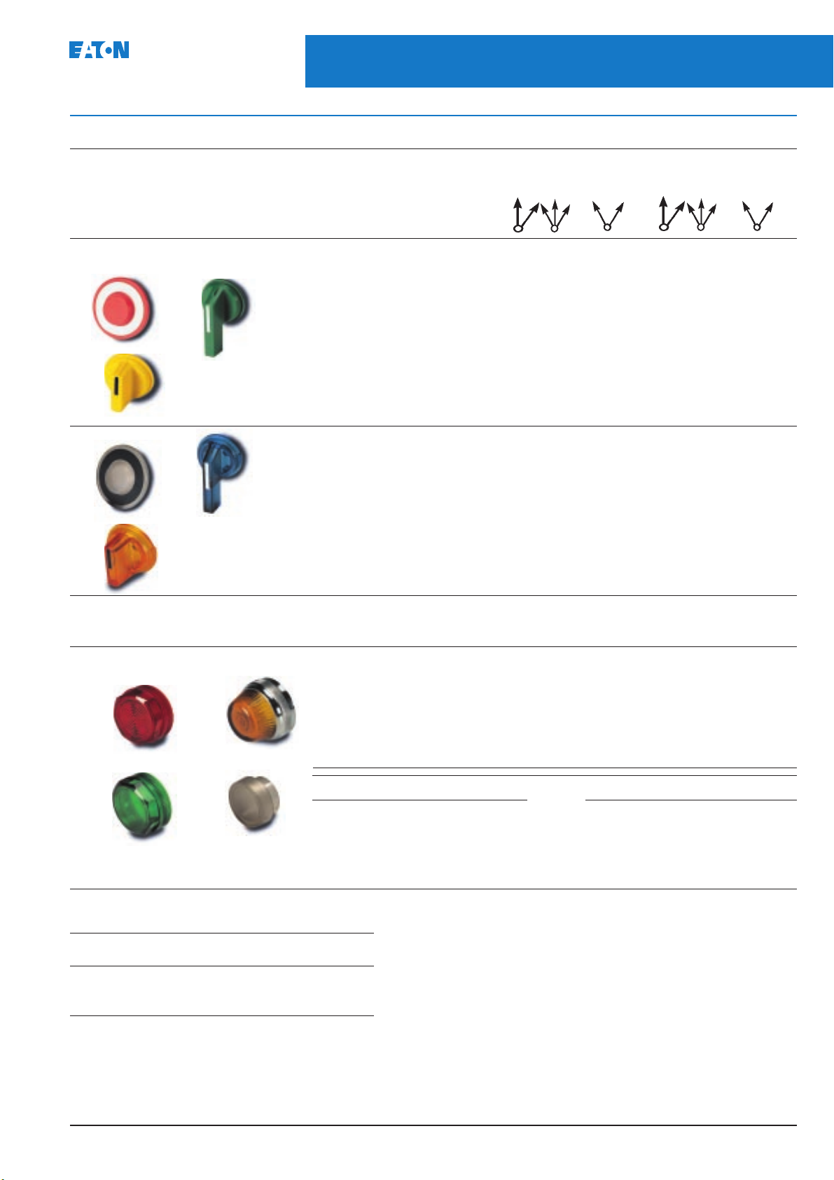
August 2004
Accessories (continued)
22.5mm Pushbuttons, Indicating Lights and
Selector Switches
E22 Series - Accessories
23
Description Colour Catalogue numbers
Replacement caps, levers and Black E22AHS1 E22AH1 E22AV1 E22AV21 E22AX1 E22AX21
knobs – Non-illuminated Red E22AHS2 E22AH2 E22AV2 E22AV22 E22AX2 E22AX22
Green E22AHS3 E22AH3 E22AV3 E22AV23 E22AX3 E22AX23
Yellow E22AHS4 E22AH4 E22AV4 E22AV24 E22AX4 E22AX24
White E22AHS5 E22AH5 E22AV5 E22AV25 E22AX5 E22AX25
Caps Levers Blue E22AHS6 E22AH6 E22AV6 E22AV26 E22AX6 E22AX26
Grey E22AHS7 E22AH7 E22AV7 E22AV27 E22AX7 E22AX27
Orange E22AHS8 E22AH8 E22AV8 E22AV28 E22AX8 E22AX28
Red marked
EMERGENCY STOP – E22AH2N8 – – – –
Knobs
Illuminated Clear E22AFS0 E22AF0 E22AW0 E22AW20 E22AR0 E22AR20
Red E22AFS2 E22AF2 E22AW2 E22AW22 E22AR2 E22AR22
Green E22AFS3 E22AF3 E22AW3 E22AW23 E22AR3 E22AR23
Yellow E22AFS4 E22AF4 E22AW4 E22AW24 E22AR4 E22AR24
Caps Levers White E22AFS5 E22AF5 E22AW5 E22AW25 E22AR5 E22AR25
Blue E22AFS6 E22AF6 E22AW6 E22AW26 E22AR6 E22AR26
Amber E22AFS9 E22AF9 E22AW9 E22AW29 E22AR9 E22AR29
Red marked
EMERGENCY STOP – E22AF2N8 – – – –
Knobs
Push-pull cap Selector switch Selector switch
29.5mm 40mm Levers Knobs
Description Colour Catalogue numbers
Replacement lenses – Clear E22AE0 E22AG0 E22AC0 E22AE20
indicating lights Red E22AE2 E22AG2 E22AC2 E22AE22
Green E22AE3 E22AG3 E22AC3 E22AE23
Yellow E22AE4 E22AG4 ––
White E22AE5 E22AG5 E22AC5 E22AE25
Standard Glass Blue E22AE6 E22AG6 E22AC6 E22AE26
lens lens Amber E22AE9 E22AG9 E22AC9 E22AE29
* Printed insert Catalogue no.
Without marking E22AL5
Motor run E22AL5N81
Motor running E22AL5N56
Lens for printed Printed
insert insert
Motor stopped E22AL5N57
Off E22AL5N24
Standard Lens for Glass Lens for
lens printed insert* lens double pushbutton
* Printed insert Catalogue no.
On E22AL5N25
Power on E22AL5N80
Supply on E22AL5N61
Special legend E22AL5N36X
Spare keys
Description Ref. Catalogue
2 Standard keys 92239 E22KS2
1 Master key 92 E22KM92
(For all non-standard locks)
For spare keys of locks not listed please contact Eaton
no. numbers
PGO4700001U
Page 25

24
22.5mm Pushbuttons, Indicating Lights and
Selector Switches
E22 Series - Enclosures - polycarbonate
Enclosures – polycarbonate
Main features
Polycarbonate enclosures
IP65 ingress protection
Quick release stainless steel screws
August 2004
Double insulated
Colour light grey
Description Usable Catalogue Weight Overall
Single way
Grey base and 56mm E22CSP1 0.1
grey lid 86mm E22CDP1 0.1
Grey base and 56mm E22CSP1Y 0.1
yellow lid 86mm E22CDP1Y 0.1
Two way 56mm E22CSP2 0.2
Mounting matrix 86mm E22CDP2 0.4
36mm
Three way 56mm E22CSP3 0.2
Mounting matrix 86mm E22CDP3 0.4
36mm
Four way 56mm E22CSP4 0.2
Mounting matrix 86mm E22CDP4 0.4
30mm
depth numbers (kg) dimensions (mm)
Six way 81mm E22CDP6 0.6
Mounting matrix
36mm x 47mm
PGO4700001U
Page 26

August 2004
Enclosures – die cast aluminium
Main features
Powder coated paint finish
IP65 ingress protection
22.5mm Pushbuttons, Indicating Lights and
Selector Switches
E22 Series - Enclosures - die cast aluminium
Threaded conduit entry
Colour light grey RAL 7032
25
Description Usable Catalogue Weight Overall
Single way
Grey base and 50mm E22CDD1 0.05
grey lid
Grey base and 50mm E22CDD1Y 0.05
yellow lid
Two way
Mounting matrix 50mm E22CDD2 0.65
47mm
Three way
Mounting matrix 50mm E22CDD3 0.76
47mm
depth numbers (kg) dimensions (mm)
PGO4700001U
Page 27

26
22.5mm Pushbuttons, Indicating Lights and
Selector Switches
E22 Series - Assembled stations
Assembled stations
August 2004
Description Operator Button Contact Catalogue numbers Operator Weight
Single way 40 mm mushroom Red N.C. E22AS105 E22ASB105 0.2
40 mm mushroom Red N.C. E22AS106 E22ASB106 0.2
40 mm mushroom Red N.C. E22AS107 E22ASB107 0.23
(latch-in key
release) Yellow
background (IP54)
Start (flush) Green N.O. E22AS108 E22ASB108 0.2
Stop (extended) Red N.C. E22AS109 E22ASB109 0.2
Two way Start (flush) Green N.O.
Stop (extended) Red N.C. E22AS204 E22ASB204 0.32
(flush) Black N.O.
(flush) Black N.O. E22AS207 E22ASB207 0.32
colour arrange- Chrome Black dimensions (mm) (kg)
ment bezel bezel
(spring return)
Yellow background
(latch-in twist
to release)
Yellow background
with legend
with legend
Start (flush) Green N.O.
Stop (40 mm mushroom
spring return) Red N.C. E22AS205 E22ASB205 0.32
Start (flush) Green N.O.
Stop (40 mm mushroom
latch-in twist to
release) Red N.C. E22AS206 E22ASB206 0.37
Three way Forward (flush) Black N.O.
Stop (extended) Red N.C.
Reverse (flush) Black N.O. E22AS304 E22ASB304 0.5
Open (flush) Black N.O.
Stop (extended) Red N.C.
Close (flush) Black N.O. E22AS305 E22ASB305 0.5
Up (flush) Black N.O.
Stop (extended) Red N.C.
Down (flush) Black N.O. E22AS306 E22ASB306 0.5
(flush) Black N.O.
(extended) Red N.C.
(flush) Black N.O. E22AS307 E22ASB307 0.5
PGO4700001U
Page 28

22.5mm Pushbuttons, Indicating Lights and
August 2004
Technical data
Operator forces
Operation Initial force (N) Final force (N)
Pushbutton 25mm 2.25 5.6
Mushroom 3 6.9
2 Position push/pull 16 0
3 Position push/pull Push 0 22.3
Pull 0 33.5
Single circuit contact block E22B2 N.O. contact block 1 4.45
E22B1 N.C. contact block 0.3 3.4
Dual circuit contact blocks E22B20 2N.O. contact block 0.8 5.9
E22B11 1N.O. + 1N.C contact block 0.6 5.4
Operator torque
Operation Initial torque (Nm) Final torque (Nm)
Key, lever & knob selectors Spring return 0.1 0.15
Maintained 0.2 0.3
Selector Switches
E22 Series - Technical data
27
Mounting (mm)
Description Dimension
Optional panel notch to provide anti-rotation.
Use E22LRP or E22LRM accessory
Mounting panel thickness– minimum 1
– maximum 6.35*
* The accessories alongside Legend plates 1.25
reduce the maximum panel Locating ring 1.5
thickness by the following Padlockable cover 2.4
amount. Rubber boots 1.3
Mounting matrix – minimum (mm)
Description 3 Way mounting adaptor 5 Way mounting adaptor
Dim 'A' Dim 'B' Dim 'A' (1) Dim 'A' (2) Dim 'B'
All operators except those below 30 50 40 50 50
3 Position lever selector switches
& 40mm operators 45 50 45 50 50
50mm operators 55 55 55 55 55
Pushbuttons assembled with
boots or padlockable covers 35 50 40 50 50
A
(1) Horizontal spacing for one 3 way & one 5 way mounting adaptor.
A
(2) Horizontal spacing for two 5 way mounting adaptors.
AC15 Electrical durability DC13 Electrical durability DC13 Electrical durability
Millions of
operations
10
8
6
4
3
2
1.0
0.8
0.6
0.4
0.3
0.2
0.1
Ue 120V
Millions of
operations
10
8
6
4
3
2
1.0
0.8
0.6
0.4
0.3
0.2
Ie Amperes
10
684321
0.1
110864320.8
Ue 24V L/R=100ms
Ie Amperes
Millions of
operations
10
8
6
4
3
2
1.0
0.8
0.6
0.4
0.3
0.2
0.1
0.01
Ue 660V L/R=100ms
Ie Amperes
0.20.030.02 0.04 0.06 0.08
0.1
PGO4700001U
Page 29

Page 30

22.5mm Pushbuttons, Indicating Lights and
August 2004
Mushroom Selector switch Rotary cam Transformer light Non-transformer Indicating Monoblock
operators operators selector switches source units light source units lights indicating lights
IEC947-5-1, IEC337-1, BS4794, VDE0660, UL508, CSA22.2 no 14, Lloyds IEC337-1
– – EN50013 (BS5581) EN50013 (BS5581) EN50013 (BS5581) EN50013 (BS5581) EN50013 (BS5581)
IP65 IP65 IP65 – – IP65 –
Type 4, 4x, 13 Type 4, 4x, 13 Type 4, 4x, 13 – – Type 4, 4x, 13 –
– – – IP20 IP20 – IP10
300,000 500,000 2,000,000 – – – –
1,200 3,000 3,000 – – – –
70g 55g (key) 106g (4 circuit) 80g 14g 23g 21g
43g (lever) 115g (6 circuit)
125g (8 circuit)
33 3 3 3 3 3
4kV 4kV 4kV 4kV 4kV 4kV 4kV
–20 to +60°C –20 to +60°C –20 to +60°C– – – –
–20 to +60°C –20 to +60°C – –20 to +60°C –20 to +60°C –20 to +60°C –20 to +60°C
5g 5g – 5g 5g 5g –
30g 30g 30g✝ 30g 30g 30g –
25g 25g 25g✝ 25g 25g 25g –
–40 to +80°C –40 to +80°C –40 to +80°C –40 to +80°C –40 to +80°C –40 to +80°C –40 to +80°C
Any Any Any Any Any Any Any
2000m 2000m 2000m 2000m 2000m 2000m 2000m
Selector Switches
E22 Series - Technical data
29
–– 2 2 2 – 2
– – 1.5 2.5 2.5 – 2.5
– – 0.75 0.75 0.75 – 0.75
✝ Rotary cam selector switches having no more than 4 circuits.
Contact ratings – Rotary cam switches
Thermal current Ith 10A
Insulation voltage Ui 500V
Operating frequency limits 50-60Hz
Adjacent contacts 'electrically separate' Yes
AC1 duty Ue VA Ie
Resistive or low inductive loads 380V 3,800 10A
AC11 duty
Control of A.C. electromagnets 240V 600 2.5A
440V 660 1.5A
AC21 duty
Switching of resistive loads, including
moderate overloads 500V 5,000 10A
AC22 duty
Switching of combined resistive or inductive
loads, including moderate overloads 500V 5,000 10A
Short circuit co-ordination
Conditional short circuit current Ig 3kA
Fuse type BS88 type gG 10A
Circuit breaker type To be announced
DC switching capacity
Number of 1 234568Amperes
series contacts Voltage (V)
DC1 resistive 24 48 70 95 120 144 190 10
loads 48 95 140 190 240 290 350 6
L/R<=1ms 60 120 180 240 300 360 450 2.5
110220330440–––0.7
220440–––––0.3
440––––––0.2
DC1 inductive 24 48 72 96 120 144 190 6
loads 30 60 90 120 150 180 240 3
L/R<=50ms 48 95 140 190 240 290 350 1
60 120 180 240 300 360 450 0.7
110220330440–––0.3
UL & CSA ratings
Maximum rated voltage 300V ac
Switching capacity, heavy pilot duty A300 3A ac
DOL motor load 3 phase 240V 1HP
1 phase 120V 0.33HP
240V 0.75HP
PGO4700001U
Page 31

30
22.5mm Pushbuttons, Indicating Lights and
Selector Switches
E22 Series - Technical data
Technical data – Trigger action actuators
August 2004
Description
The E22LTA2 is a latching, trigger-action, twist-to-release pushbutton
actuator designed specifically for use as an Emergency Stop Switch.
The E22MGTA is a rectangular guard designed to prevent accidental or
inadvertent actuation of the E22TLA actuator. It is also designed to permit
easy knob rotation access for manually resetting the switch.
The E22CB1, E22CB11 & E22CB1E contact blocks are specially marked
contact blocks indicating compliance with IEC 60947-5-1 Annex K.
Application
The E22LTA2 actuator and E22CB* contact blocks are intended to be the
primary and/or one of several series-connected emergency stop switches in
a control panel. The N.C. (normally closed), break electrical contacts are
D.O.A. (direct opening action) which are designed to be forcibly opened by
the movement of the actuator in the event that the contact should be tack
welded etc.
Key features
✮ Mushroom head button (40mm diameter) for easy actuation (per EN418
Section 4.4).
✮ Safety red coloured button per ANSI Z535.1 and EN418 Section 4.4.3.
✮ Manually resettable actuator.
✮ Rectangular guard is coloured safety yellow per ANSI Z535.1 and
provides yellow background for the actuator per EN418 Section 4.4.3.
✮ All external pushbutton and guard materials have a V-0 flammability
rating per UL94.
✮ Contact blocks are A600/Q600 rated per UL508 and AC15/DC13 rated per
IEC 60947-5-1.
N.C. (normally closed), break contact blocks are positive opening or
D.O.A. (direct opening action) in accordance with EN418 Section 4.1.2.
✮ Suitable for isolation per IEC 60947-5-1.
Environmental ratings (actuator)
Ingress protection
UL (NEMA) 1, 2, 3, 3R, 4, 4X, 12 & 13 and IEC IP 65 when mounted on a
flat surface of a similarly rated enclosure. Above ratings do not apply to
applications where devices are mounted directly unto a machine without
the use of a separate console or enclosure. If not installed in a suitable
panel or enclosure, precautions must be taken to safeguard contact blocks
against electrical contact or shock and from contamination from
environmental or working conditions of the machine.
Operating temperature
–20° to +60°C
Storage temperature
–40° to +80°C
Altitude
2,000m
Humidity
Max 95% RH @ 60°C
Flammability
UL94 V-O rated
UV resistance
Shield actuator from excessive exposure to UV, and routinely perform a
functional test of the emergency stop switch and inspect actuator for fading
and cracking after every 500 hours of UV exposure.
Mechanical endurance ratings (actuator)
Life
100,000 cycles (actuation & release)
Frequency of operation
6 per minute
Vibration
5g, 0.7mm peak to peak, 10 sweeps, 10 to 500Hz
Shock
30g, 12ms
Bump
25g, 6ms for 1,000 cycles
Electrical ratings (contact blocks)
✮ A600 & Q600 per UL508
✮ AC15 & DC13 per IEC 60947-5-1
AC Life (AC15)
120Vac, 6A - 1,000k operations
DC Life (DC13)
24Vdc, 4A - 400k operations
N.C. Contacts
DOA (direct opening action) per IEC 60947-5-1
Short circuit co-ordination rating
1kA
Short circuit co-ordination fuse
GE Power Controls TIA 10, Red Spot type gG, 10A 660Vac 460Vdc, BS88-2,
per IEC 60269-2-1
Standards & certifications
✮ UL Listed E-Stop device per file # E217948
✮ Certified to EN 60947-5-1 & EN 60947-5-5 per DEMKO certificate
# 129648-01/A1
✮ Certified to EN418 per DEMKO Certificate # 129648-02/A2
✮ UL508 listed per file # E131568
✮ CSA certified per file # LR68551
PGO4700001U
Page 32

August 2004
30.5mm Pushbuttons, Indicating Lights and
Selector Switches
91000T Series
31
30.5mm operators – 91000T Series
Description Page
Pushbutton operators 32
Mechanical push operators 32
Illuminated pushbuttons 33
Cylinder lock pushbuttons 33
Contact blocks 33
Knob or lever operated selector switches 34
Key operated selector switches 35
Standard indicating lights 36
Prestest Indicating lights 37
PGO4700001U
Description Page
Roto-push pushbuttons 38
Joystick controllers 39
Legend plates 40
Accessories 41
Assembled pushbutton stations 43
Emergency stop stations 43
Aluminium alloy enclosures 44
Technical data 45
Page 33

Page 34

30.5mm Pushbuttons, Indicating Lights and
August 2004
Illuminated pushbuttons BA9s bayonet fitting. For replacement bulbs see page 42.
Selector Switches
91000T Series - Illuminated and cylinder lock pushbuttons and contact blocks
33
Description Supply voltage Catalogue Overall Weight
Transformer type 110/120 91000T411 0.19
6V 1W secondary. 220/240 91000T412 0.19
Bulb supplied 380/415 91000T413 0.19
Direct voltage
Supplied without bulb 6 to 240 91000T441 0.093
Operator
BA9s bayonet bulbs (for use with 91000T441)
Filament type 6V (1W) flasher 28-2225-26
Lens
Neon type 110V (0.8mA) 28-2225-48
LED Bulbs see page 37
Plastic lens (for use with illuminated pushbuttons).
Colour Catalogue numbers
Red 91000TC21
Green 91000TC22
50/60Hz numbers dimensions (mm) (kg)
440/480 91000T414 0.19
6.3V (1W) 28-2225-72
12V (1.2W) 28-2225-29
24V (1.2W) 28-2225-30
28V (1.12W) 28-2225-73
50V (1W) 28-2225-31
60V (1.2W) 28-2225-32
110V (2.2W) 28-2225-24
240V (1.5mA) 28-2225-49
Colour Catalogue numbers
Amber 91000TC43
Blue 91000TC24
Colour Catalogue numbers
Clear 91000TC25
White 91000TC26
Cylinder lock pushbuttons
Operators (Supplied with the standard lock and 2 keys, key ref. H661).
Key position and pushbutton operation Key Catalogue Weight
Left Centre Right positions
Lock-up Free Lock down All 91000T430 0.185
Blocked Free Push to lock C & R 91000T437 0.185
Special lock selection: Add the appropriate suffix code from page 35. eg 91000T430H620.
removal numbers (kg)
Contact blocks
Description Catalogue numbers: Overall Weight
1 N.O. 1 N.C. 91000T1 0.025
2 N.O. 91000T2 0.025
2 N.C. 91000T3 0.025
1 N.C. 91000T51 0.025
1 N.O. 91000T53 0.025
2 N.O. 2 N.C. 91000T44 0.025
1 N.O. 1 N.C.
make before break 91000T55 0.025
Note:
A maximum of 6 blocks (12 circuits) may be fitted to each operator except for 91000T44 where a maximum of 4 blocks (16 circuits) may be fitted.
* For base mounting contact blocks see page 44.
One-hole mounting * dimensions (mm) (kg)
PGO4700001U
Page 35

34
30.5mm Pushbuttons, Indicating Lights and
Selector Switches
91000T Series - Knob or lever operated selector switches
Knob or lever operated selector switches
Bare shaft operator
Description Cam code Catalogue Overall Weight
2-position
Stayput 1 91000T4011 0.115
Spring return right to left 1 91000T4081 0.115
3-position
Stayput 2 91000T4022 0.115
3 91000T4023 0.115
4 91000T4024 0.115
6* 91000T4026 0.115
Spring return from left, 2 91000T4032 0.115
stayput centre and right 3 91000T4033 0.115
Spring return to centre 2 91000T4042 0.115
from left and right 3 91000T4043 0.115
August 2004
numbers dimensions (mm) (kg)
Stayput left and centre, 2 91000T4052 0.115
spring return from right 3 91000T4053 0.115
Knob (for any operator) 91000TKB
Lever (for any operator) 91000TLB
Cam selection chart showing contact sequence
To determine the number of the cam you require and the right contact block select the contact sequence desired from table below. O = contacts open,
X = contacts closed. The cam number is shown at top of column. The catalogue number of the appropriate contact block is shown at extreme left of table.
Catalogue numbers Circuit 2-position 3-position selector
of contact block (see note (1) selector switch
One-hole Base at foot of switch
mounting mounting table)
Cam Cam Cam Cam Cam
code code code code code
no. 1 no. 2 no. 3 no. 4 no. 6 ✝
91000T1 91000T6 A N.C. XO OXO OXX XOO XOO
B N.O. OX OOX OOX OXO OXO
91000T1 91000T6 A N.O. OX XOX XOO OXX OOX
B N.C. XO XXO XXO XOX OOX
91000T2 91000T7 A N.O. OX XOX XOO OXX OOX
B N.O. OX OOX OOX OXO OXO
91000T3 91000T8 A N.C. XO OXO OXX XOO XOO
B N.C. XO XXO XXO XOX OOX
Switching angle.
60° between each position.
Note:
(1) Each contact block contains two contact circuits. The top set of contacts is identified as ‘Circuit A’ and the lower set as ‘Circuit B’ is indicated in the table.
The chart shows the contact arrangements with the three contact blocks available and in each operator position. Additional contact combinations are obtainable
by stacking contact blocks in tandem up to a maximum of 6 blocks (12 circuits).
✝
A maximum of 2 are to be used with cam 6. Rated fo A.C. only.
PGO4700001U
Page 36

Page 37

36
30.5mm Pushbuttons, Indicating Lights and
Selector Switches
91000T Series - Standard indicating lights
Standard indicating lights
August 2004
Lamp units Bulbs supplied with units unless otherwise stated.
Description Supply volts Catalogue Overall Weight
Transformer type 110/120 91000T181N 0.22
6V 1W secondary BA9s 220/240 91000T182N 0.22
bayonet bulb under rated by 380/415 91000T183N 0.22
10% for longer life. 550/600 91000T185N 0.22
Resistor type
120V 2.2W 110/120 91000T201N 0.112
BA9s bayonet bulb 220/240 91000T202N 0.112
Direct voltage unit (MCC/MBC)
Supplied without bulb. Suitable
for BA9s bayonet bulbs 6 to 240 91000T197N 0.11
BA9s bayonet bulbs (for use with 91000T197N)
Filament type 6V (1W) flasher 28-2225-26
Neon type 110V (0.8mA) 28-2225-48
For replacement light bulbs see page 42
50/60Hz numbers dimensions (mm) (kg)
6.3V (1W) 28-2225-72
12V (1.2W) 28-2225-29
24V (1.2W) 28-2225-30
28V (1.12W) 28-2225-73
50V (1W) 28-2225-31
60V (1.2W) 28-2225-32
110V (2.2W) 28-2225-24
240V (1.5mA) 28-2225-49
LED Bulbs see page 37
Lenses
Plastic
Direct voltage unit (SBC)
Supplied without bulb. Suitable
for BA15d bayonet bulb 6 to 240 91000T200N 0.11
BA15d bulbs (filament type) 6 28-2225-18
6 – 10 watt. 12 28-2225-19
For use with 91000T200N 24 28-2225-20
48 28-2225-21
130 28-2225-22
240 28-2225-23
Colour Catalogue numbers
Plastic Glass
Red 91000TC1N 91000TC7N
Green 91000TC2N 91000TC8N
Amber 91000TC19N 91000TC9N
Blue 91000TC4N 91000TC10N
Clear 91000TC5N 91000TC11N
White 91000TC6N 91000TC12N
Glass
PGO4700001U
Page 38

Page 39

38
30.5mm Pushbuttons, Indicating Lights and
Selector Switches
91000T Series - Roto-push pushbuttons
August 2004
Roto-push pushbutton (a combined selector switch and pushbutton)
Description Button Catalogue numbers Overall Weight
colour Vertical Horizontal dimensions (kg)
mounting mounting (mm)
Black 91000T241* 91000T251* 0.128
Green 91000T243* 91000T253* 0.128
*
Complete the catalogue number by adding the respective cam code number from the table below. Example: 91000T24111 is a 2 position roto-push for use as shown below.
Typical application run-inch, start-inch
2 position roto-push 91000T24111 + 91000T1
With the roto-push sleeve turned to Inch depression of the push energises
coil M through circuit A only so long as the push is pressed i.e. the motor
will inch. With the roto-push sleeve turned to Run, the roto-push contact
connected to the maintaining contact of M through circuit B is
permanently closed, thus when the push is pressed (circuit A) M will close
and maintain itself and the motor will run.
Cam selection chart showing contact sequence
O = contacts open, X = contacts closed. The catalogue number of the appropriate contact block is shown at extreme left of table.
Catalogue number Button Circuit ✝ 2 position operators 3 position
of contact block position operators
One hole Base Cam code number
mounting mounting 1 2 34561011 789
91000T1 91000T6 N A N.C. XX XX XO XX XX XO XX XX XXX XOX XOO
N B N.O. OO OO OX OX OX OX OX OX OXX OXO OOX
D A N.C. XO XO OO OO XO XO OX OO OXO OOX XOO
D B N.O. XO XX XX XX OX XX OX OX OXX OXX OOX
91000T1§ 91000T6§ N A N.O. OO OO OX OO OO OX OO OO OOO OXO OOX
N B N.C. XX XX XO XO XO XO XO XO XOO XOX XXO
D A N.O. OX OX XX XX OX OX XO XX XOX XXO OXX
D B N.C. OX OO OO OO XO OO XO XO XOO XOO XXO
91000T2 91000T7 N A N.O. OO OO OX OO OO OX OO OO OOO OXO OOX
N B N.O. OO OO OX OX OX OX OX OX OXX OXO OOX
D A N.O. OX OX XX XX OX OX XO XX XOX XXO OXX
D B N.O. XO XX XX XX OX XX OX OX OXX OXX OOX
91000T3 91000T8 N A N.C. XX XX XO XX XX XO XX XX XXX XOX XOO
N B N.C. XX XX XO XO XO XO XO XO XOO XOX XXO
D A N.C. XO XO OO OO XO XO OX OO OXO OOX XOO
D B N.C. OX OO OO OO XO OO XO XO XOO XOO XXO
Cam codes 6 & 7 are for ac use only.
Note:
✝
Each contact block contains two contact circuits. The top set of contacts is identified as ‘circuit A‘ and the lower set as ‘B‘. The table shows contact
arrangement of each contact block with the operating button in normal and depressed positions and in each rotary sleeve position.
Additional combinations are obtainable by stacking contact blocks in tandem.
§
These contact blocks are the same as the ones above except rotated 180
Switching angle: 60° N = Button in free or normal position D = Button depressed
°
when assembled to the operator.
PGO4700001U
Page 40

August 2004
Joystick controllers
30.5mm Pushbuttons, Indicating Lights and
Selector Switches
91000T Series - Joystick controllers
Eight circuit
Non-latched operator
39
Supplied with 4 position gate fitted
3 additional gates supplied which
allows conversion to 2, 3 or 8
positions. (T1030, T1050, T1020)
Up to eight switching positions
Up to twelve circuits.
Each circuit N.O. or N.C.
required a.c. or d.c.
Description Catalogue numbers Overall
Without latch: With off position latch: dimensions (mm)
Spring return
only 91000T450 91000T460
Field adjustable
spring return to
stayput 91000T451 91000T461
Contact blocks
Description Catalogue numbers
1 N.O. – N.C. 91000T1
2 N.O. 91000T2
Panel drilling
dimensions (mm)
2 N.C. 91000T3
1 N.O. 1N.C. make before break 91000T55
Legend plates
Description Catalogue numbers
Blank 91000TJS1
Engraved 91000TJS2
Hole plug 91000TA700
With controllers mounted
adjacent to each other
A = 101.6 B = 111.1
With 91000T pushbuttons
or indicating light mounted
adjacent to joystick controller
A = 60.3 B = 95.2
Positioning gate 91000T1010 is fitted as standard to each operator
The arrows shown in the ‘Handle positions’ column A indicates the handle positions and movements available when the indent mark on the gate is adjacent to the
letter A on the handle assembly base casting. (No indent mark is provided on gates 91000T1010 and T1020).
Handle position Handle position
Gate
profile
A B C D
Catalogue
numbers
91000T1010
91000T1020
91000T1030
91000T1040
91000T1050
91000T1060
91000T1070
91000T1080
91000T1090
*
These positioning gates are identical with the one immediately above them. The handle positions shown against these profiles are obtained when the
Gate
profile
A B C D
Catalogue
numbers
91000T1100
91000T1110
91000T1120
91000T1130
91000T1130*
91000T1140
91000T1150
91000T1150*
91000T1160
positioning gate is fitted with the indent mark not visible i.e. in contact with the common gate.
PGO4700001U
Page 41

40
30.5mm Pushbuttons, Indicating Lights and
Selector Switches
91000T Series - Legend plates
Legend plates
August 2004
Medium Large
Legend Catalogue numbers
Medium Large
91000T 91000T
Auto off hand M49 J49
(Blank) M36 J36
(Blank)§ M37 J37
(Blank) M95✝ J95✝
(Blank)§ M96✝ J96✝
Close M11 J11
Down M12 J12
Emerg Stop§ M13 –
Emergency
Stop§ – J13
Fast M14 J14
For Off Rev M50 J50
For Rev M38 J38
Forward M15 J15
Hand Auto M39 J39
Hand Off Auto M51 J51
High M16 J16
High Low M40 J40
I M65 J65
In M17 J17
Inch M18 J18
Inch For M20 –
Inch Forward – J20
Inch Rev M21 –
Inch Reverse – J21
Legend Catalogue numbers
Medium Large
91000T 91000T
Inch Run M41 J41
Inch Safe Run M52 J52
Jog M19 J19
Left M73 J73
Left Right M74 J74
Local Off
Remote M66 J66
Local Remote M63 J63
Low M22 J22
Lower M23 J23
Man Auto M67 J67
Man Off Auto M68 J68
Motor Run M58 J58
Motor Running M56 J56
Motor Stop§ M59 J59
Motor Stopped M57 J57
O§ M64 J64
Off§ M24 J24
Off On M42 J42
On M25 J25
Open M26 J26
Open Close M43 J43
Open Off Close M53 J53
Out M27 J27
Power On M55 J55
Legend Catalogue numbers
Medium Large
91000T 91000T
Raise M28 J28
Raise Lower M76 J76
Ready M78 J78
Reset M29 J29
Reverse M30 J30
Right M79 J79
Run M31 J31
Run Inch M44 J44
Safe Run M45 J45
Seq. Test M62 J62
Slow M32 J32
Slow Fast M84 J84
Slow Off Fast M85 J85
Start M33 J33
Start Inch M46 J46
Start Stop M47 J47
Stop§ M34 J34
Stop Reset§ M88 J88
Stop (Turn barrel
to release)§ M90 –
Supply On M61 J61
Test M60 J60
Up M35 J35
Up Down M48 J48
Up Off Down M54 J54
The standard colour field is black, except for those legends marked
Non-standard legends
If a legend not quoted above is required, give the blank catalogue number
for the size/colour and add the suffix ‘X’ to the code, indicating (e.g. by
dashes not to be reproduced on the plate) the number of positions to be
catered for, e.g. M36X JET-OFF-SPRAY (medium, black, 3-position).
The following table gives the maximum number of letters of a certain size
which can be engraved on standard legend plates.
Type Letter size (mm)
1.6 3.2 4.8 6.4 8 9.5 12.7
No.of No.of No.of No.of No.of No.of No.of No.of No.of No.of No.of No.of No.of No.of
lines letters lines letters lines letters lines letters lines letters lines letters lines letters
Medium3242121816 14 14––
Large 6 30 4 15 3 10 2 7 2 5 1 5 1 3
§
for which the standard colour is red. Legends marked thus ✝ are of brass. All other legends are of aluminium.
Dimensions (mm)
Note:
Two large size legend
plates cannot be mounted
one above the other on
standard enclosures.
PGO4700001U
Page 42

August 2004
Accessories
Padlock attachments
Boots
30.5mm Pushbuttons, Indicating Lights and
Selector Switches
91000T Series - Accessories
Description Catalogue numbers
Padlock attachment for stop 91000TA2
button. Permits locking N.C.
contacts in open position,
prevents operation of button
Padlock attachment with hinged 91000TA38
transparent flap, for flush or
extended pushbuttons, and
knob-operated selector switches
Protective boot for flush Blue 91000TA46
pushbutton operators Black 91000TA47
Red 91000TA48
Green 91000TA49
Yellow 91000TA50
41
Guards and shrouds
Protective boot for mushroom Black 91000TA88
and palm pushbutton operators.
Not suitable for use with
91000T140
Protective boot for extended Black 91000TA3
pushbutton operators Red 91000TA4
Green 91000TA10
Guard sleeve for flush 91000TA12
pushbutton
Guard sleeve for mushroom 91000TA6
head operator. Chrome
finish. Prevents accidental
operation. Not suitable for use
with 91000T140
Guard sleeve for illuminated 91000TA15
pushbutton. Prevents
accidental operation
Lever operator
Description Catalogue number
Lever for release of a 91000TA13
staydown pushbutton
or roto-push operator.
PGO4700001U
Page 43

42
Selector Switches
91000T Series - Accessories
Accessories
30.5mm Pushbuttons, Indicating Lights and
August 2004
Trip and reset attachment
Description Catalogue number
Trip and reset attachment. Use with 91000TA1
two pushbutton operators and one
or more contact blocks. The contact
blocks are mounted under the reset
or stop push which latches in the
depressed position until released by
depression of the trip push.
Other accessories
Description Catalogue
Wobble stick complete with 91000TA5
locking ring for mounting
on a flush pushbutton.
Designed for emergency
or hurried operation
Plug for unused hole in cover 91000TA7
Finish in light grey (RAL 7032)
numbers
Replacement light bulbs *
Type Voltage Used on Catalogue
numbers
BA9s 6 91000T181N – 185N 28-2225-26
flasher 91000T221N – 223N
filament 91000T411 – 414
BA9s 6.3 91000T181N – 185N 28-2225-72
filament 91000T221N – 223N
91000T411 – 414
BA9s 110/120 91000T201N,T202N 28-2225-24
filament 91000T231N,T240N
Note:
* Replacement bulbs are for use with current series 'B' operators. For
replacement bulbs for series 'A' (round bezelled) operators contact
Eaton Limited.
Bulb removal tool
BA9s and BA15d type bulbs 91000TA65
Description Catalogue
numbers
Boot spanner. 91000TA96
For easy installation of operators
fitted with protective boots.
2 spare keys for special
locks, state key ‘H’ code as
suffix e.g.91000TA151H620 91000TA151H*
2 spare keys for standard lock
ref. no. H661 91000TA152
Protective washer, used as 91000TA8
substitute when legend
plate is not required.
Prevents locking ring from
scratching paint.
Double ended box spanner for E22CW
easy installation of control
units on panel. (Will not fit
over selector switch levers).
Box spanner 91000TA95
Notched to fit over selector
switch levers.
6-32 stacking screws 91000TA79
for series B operators (pack of 10)
Octagonal bezel with 26 T.P.I. 91000TA202
to convert round style
pushbutton operators to octagonal
Terminal boots. 91000TA81
Provides IP20 (fingerproof (pack of 10)
protection) for terminals
PGO4700001U
Page 44

30.5mm Pushbuttons, Indicating Lights and
August 2004
Assembled pushbutton stations
Features and characteristics
Oiltight stations Surface mounted die-cast aluminium enclosures Powder coat painted
IP65 ingress protection Threaded conduit entry light grey (RAL7032)
Selector Switches
91000T Series - Assembled pushbutton and emergency stop stations
43
Description Operator Contact Catalogue Weight Operator
Single way Start N.O. – N.C. 91000T3516 0.68
station
Two way Start N.O. – N.C.
stations Stop N.C. 91000T3525 0.98
Start N.O. – N.C.
Mushroom
stop
(spring return) N.C. 91000T3526 0.98
Start N.O. – N.C.
Mushroom
stop
(auto latch) N.C. 91000T3630 0.98
arrangement numbers (kg) dimensions (mm)
Three way Forward N.O. – N.C.
stations Reverse N.O. – N.C.
Stop N.C. 91000T3532 1.3
Open N.O. – N.C.
Close N.O. – N.C.
Stop N.C. 91000T3614 1.3
Up N.O. – N.C.
Down N.O. – N.C.
Stop N.C. 91000T3615 1.3
Emergency stop stations
38mm dia. red mushroom
push. Momentary spring
return. Yellow lid. N.C. 91000T3553
38mm dia. red mushroom
push. Stop-lock, twist
barrel to release. Yellow lid
63mm dia. red palm push.
Stop lock, twist barrel to
release. Yellow lid. N.C. 91000T3555
.
N.C. 91000T3554
PGO4700001U
Note:
For enclosure dimensions see page 44.
Page 45

44
30.5mm Pushbuttons, Indicating Lights and
Selector Switches
91000T Series - Aluminium alloy enclosures
Aluminium alloy enclosures
Description Operator Catalogue numbers
Painted light grey capacity per One contact Two contact
(RAL7032) textured finish enclosure block deep: blocks deep:
1 91000TN1 91000TN11
1✝ 91000TN100 –
2 91000TN2 91000TN12
3 91000TN3 91000TN13
4 91000TN4 91000TN14
3 operator enclosure
✝
Enclosure has yellow lid
Accessories
Description Catalogue numbers
Spacers Used for base mounting contact blocks.
One required for each operator plus One contact block deep 91000TA21
additional spacer may be required Two contact blocks deep 91000TA22
to make up enclosure depth.
August 2004
Base mounting contact blocks
1 N.O. 1 N.C. 91000T6
2 N.O. 91000T7
2 N.C. 91000T8
1 N.C. 91000T52
1 N.O. 91000T54
Dimensions (mm)
1,2,3 & 4 unit sizes 1,2,3 & 4 unit sizes
single contact double contact
block depth block depth
Enclosure Dimensions Conduit Fixing Weight
size A B C D E entry holes (kg)
1 unit 97 102 68.3 82.6 69 20 5.6 0.050
2 unit 97 149 68.3 130.2 74 25 5.6 0.65
3 unit 97 197 68.3 177.8 74 32 5.6 0.775
4 unit 100 248 68.3 225 76 32 5.6 0.95
PGO4700001U
Page 46

August 2004
Technical data
30.5mm Pushbuttons, Indicating Lights and
Selector Switches
91000T Series - Technical data
45
Standards and approvals
IEC 947-5-1. MTTA*
CSA C22-2 no. 14, UL508
Ingress protection (IP ratings to IEC144 (BS5420))
IP65
IP66, NEMA 4 on pushbuttons when fitted with a rubber boot
IP65 on enclosures
Max. frequency of operations
All pushbuttons: 6000 ops/hr.
Key and lever selector switch: 3000 ops/hr.
Auto-latch devices: 1200 ops/hr.
Mechanical life
6
Pushbuttons: 10 x 10
Contact blocks: 10 x 106 operations
Prestest units: 1 x 10
Lever & key sel. sw.: 0.25 x 10⁶ operations
Twist to release p/btns: 0.3 x 10⁶ operations
Climatic conditions
Operating: Max 60°C at 95% RH.
Temp. –17°C to +66°C
Altitude 2000 metres
Storage: Max. 60°C at 95% RH.
Temp. –40°C to +80°C
Shock resistance
Shock duration: 20 ms ⊕ 5g
Electrical ratings
Rated insulation: Ui = 660V ac or dc
Rated thermal: Ith = 10A
Short circuit (IEC947-5-1): 1000A with a 6A (NIT) fuse (to BS88)
NEMA, UL rating: A600, P600
AC load life duty cycle 1200 ops/hr
10A 110V pf 0.4 - 1 x 10
5A 250V pf 0.4 - 1 x 10⁶ operations
2A 660V pf 0.4 - 1 x 10⁶ operations
Switching capacity
AC15 rated make/break (11 x le at 1.1 x Ue)
6A 120V pf 0.7
4A 240V pf 0.7
2A 660V pf 0.7
DC13 rated make/break (1.1 x le at 1.1 x Ue)
1.0A 120V L/R ⊕ 0.95 at 300ms
0.5A 240V L/R ⊕ 0.95 at 300ms
0.1A 660V L/R ⊕ 0.95 at 300ms
10A 110V pure resistive
Light units
Transformers will withstand short circuit for 1 hour per IEC947-5-1.
Bulbs average life:
Transformer type = 20,000 hrs.
Resistor/direct voltage type = 2,500 hrs min. at rated voltage.
operations
6
operations
6
operations
Low voltage switching
Conical shaped points or “reliability nibs” improve performance in dry
circuit, corrosive, fine dust and other contaminated atmospheres. Under
normal environmental conditions, the minimum operational voltage is 5V
and the minimum operational current is 1mA, ac/dc.
Contact operation
Slow make and break. All normally closed contacts have positive opening
operation. i.e. normally closed contacts are forced open in the event of
contact weld or spring breakage.
Terminal marking
Dual marking system 1 – 2 for normally closed 3 – 4 normally open to
meet BS5472 (Cenelec EN50 005) and N.C. – N.O. moulded in the contact
block to meet the NEMA requirements.
Terminal clamps
Terminals are saddle clamp types for 1 x 0.5mm˝ to 2 x 3mm˝ conductors.
Panel thickness
Maximum = 8mm including legend plate.
Minimum = 1.6mm.
*M.T.T.A. (Machine Tool, Trades Association)
A range of pushbutton operators to meet the requirements of M.T.T.A.
standard “Electrical Equipment of Machine tools and other industrial
machines and equipment for the automobile industry” are included in the
91000T range.
Mounting matrix
Legend plate A B C D
Medium 57 45 45 57
Large 57 57 57 57
Horizontal Vertical
mounting mounting
Vertical mounting means terminals are left & right of contact block.
Horizontal mounting means terminals are top & bottom of contact block.
This allows close spacing of adjacent operators with easy access to
terminals.
PGO4700001U
Page 47

August 2004
Stacklights
E26 Series
47
Stacklights – E26 Series
Description Page
Product description 48
Catalogue number selection guide 48
Light and xenon strobe modules 49
Accessories 50
LEDs - Cluster or cylindrical 53
PGO4700001U
Description Page
Technical data 54
Application data 54
Mounting options and dimensions 55
Dimensions 56
Page 48

48
Stacklights
E26 Series - Product description
Product description
The E26 Stacklight unit is a modular system that
provides illuminated and audible status indication
in all directions. Easily assembled plug-in modular
units include constant, flashing and strobe light
units, as well as mono-tonal, bitonal, intermittent
alarm systems. Stacklights may be assembled in a
variety of configurations, which are identified in
the Maximum Configurations table below.
Numerous lamp, colour and mounting options
further enhance the Stacklight’s versatility.
Light module
Light modules
Available in a variety of colours for both
incandescent lamps and LED lamps. To maximise
illumination and light dispersion, incandescent
units include an opal white diffuser while LED
diffusers are clear. See page 49.
Standard base
and top cover
Standard Stacklight base
For use with incandescent or standard LED for
steady, non-flashing illumination or with flashing
LEDs for flashing illumination. Bases include
terminal block for wiring, stacklight cover and
gasket. See page 50.
Flashing base
and top cover
Flashing Stacklight base
Allows configuration of each light in the stack for
either steady or 60 times per minute flashing
illumination. Flashing circuit for use with
incandescent lamps only. (Maximum allowable
number of light modules is 2 at 12V, 4 at 24V and
6 at 48V and above.) See page 50.
For flashing LEDs use standard base with flashing
LED light module.
August 2004
Alarm
Alarms
May be fitted to the top of a complete Stacklight
unit or directly to the Stacklight bases, if desired.
Available in three versions, each with adjustable
sound levels. See page 51.
Features
● Modular construction
● Wide variety of lens colours
● Variety of lamp types and voltages
● Mono-tonal, bi-tonal and intermittent alarm
systems
Benefits
● Combination of visible and audible alarms
● Modular components reduce inventory
requirements, increase flexibility
● Steady and flashing modes allow one light to
signal multiple conditions
● No-tools assembly permits easy lamp
replacement
Alarm
Xenon strobe
Sets are similar to standard lens/diffuser units,
except each set consists of two lens units. The
lower unit includes the electronics and is
permanently fused to the upper unit which contains
the Xenon lamp. Xenon units may be placed in any
position in a complete Stacklight unit. They will
flash 60 times per minute when used with a
standard or flashing base. See page 49.
Catalogue number selection
Complete Stacklight modules
✮ Stacklights accept a maximum of 6
incandescent or LED light modules or 2 Xenon
flasher modules and can be mounted in any
position on the stack.
✮ Alarm units are mounted in the top most position
only.
Maximum configurations
Incandescent Xenon Alarm Max.
or modules modules number of
LED modules modules
6––6
5–16
41–5
3115
22–4
1214
Level
3
Level
2
Level
1
Stacklight
base
Extension
tube
Mounting
base
Complete Stacklight
module
PGO4700001U
Page 49

Stacklights
E26
August 2004
Light and xenon strobe modules (includes lens, diffusers and bulbs unless otherwise noted)
● Light modules include lens diffusers
which provide even illumination and
eliminate hot spots.
● Xenon strobes emit a bright
attention-getting white flashing
light. Flash rate = 60/min.
● Xenon strobe modules occupy two
positions in the Stacklight assembly.
LED/Lamp Lens Incandescent Cluster LED Cylindrical LED Xenon
voltage colour Catalogue numbers Catalogue numbers Catalogue numbers Catalogue numbers
Steady or Flashing Steady Flashing Steady only Flashing
Without bulb Red E26B2 E26BR E26BR E26BR –
or LED Green E26B3 E26BG E26BG E26BG –
Yellow E26B4 E26BY E26BY E26BY –
Blue E26B6 E26BB E26BB E26BB –
Amber E26B9 E26BA E26BA E26BA –
Clear E26B0 E26BW E26BW E26BW –
12V ac/dc Red E26B2V1 E26BRV1 E26BEV1 E26BR1V1 E26BX2V1
Green E26B3V1 E26BGV1 E26BUV1 E26BG1V1 E26BX3V1
Yellow E26B4V1 E26BYV1 E26BVV1 E26BY1V1 E26BX4V1
Blue E26B6V1 E26BBV1 E26BKV1 E26BB1V1 E26BX6V1
Amber E26B9V1 E26BAV1 E26BZV1 E26BA1V1 E26BX9V1
Clear E26B0V1 E26BWV1 E26BMV1 E26BW1V1 E26BX0V1
24V ac/dc Red E26B2V2 E26BRV2 E26BEV2 E26BR1V2 E26BX2V2
Green E26B3V2 E26BGV2 E26BUV2 E26BG1V2 E26BX3V2
Yellow E26B4V2 E26BYV2 E26BVV2 E26BY1V2 E26BX4V2
Blue E26B6V2 E26BBV2 E26BKV2 E26BB1V2 E26BX6V2
Amber E26B9V2 E26BAV2 E26BZV2 E26BA1V2 E26BX9V2
Clear E26B0V2 E26BWV2 E26BMV2 E26BW1V2 E26BX0V2
48V ac/dc Red E26B2V3 E26BRV3 E26BEV3 E26BR1V3 E26BX2V3
Green E26B3V3 E26BGV3 E26BUV3 E26BG1V3 E26BX3V3
Yellow E26B4V3 E26BYV3 E26BVV3 E26BY1V3 E26BX4V3
Blue E26B6V3 E26BBV3 E26BKV3 E26BB1V3 E26BX6V3
Amber E26B9V3 E26BAV3 E26BZV3 E26BA1V3 E26BX9V3
Clear E26B0V3 E26BWV3 E26BMV3 E26BW1V3 E26BX0V3
120V ac * Red E26B2V4 E26BRV4 E26BEV4 E26BR1V4 E26BX2V4
Green E26B3V4 E26BGV4 E26BUV4 E26BG1V4 E26BX3V4
Yellow E26B4V4 E26BYV4 E26BVV4 E26BY1V4 E26BX4V4
Blue E26B6V4 E26BBV4 E26BKV4 E26BB1V4 E26BX6V4
Amber E26B9V4 E26BAV4 E26BZV4 E26BA1V4 E26BX9V4
Clear E26B0V4 E26BWV4 E26BMV4 – E26BX0V4
240V ac * Red E26B2V5 E26BRV5 E26BEV5 – E26BX2V5
Green E26B3V5 E26BGV5 E26BUV5 – E26BX3V5
Yellow E26B4V5 E26BYV5 E26BVV5 – E26BX4V5
Blue E26B6V5 E26BBV5 E26BKV5 – E26BX6V5
Amber E26B9V5 E26BAV5 E26BZV5 – E26BX9V5
Clear E26B0V5 E26BWV5 E26BMV5 – E26BX0V5
Incandescent bulbs are ac/dc rated, LEDs are ac rated only.
*
Stacklights
E26 Series - Light and xenon strobe modules
Light/LED
module
49
PGO4700001U
Page 50

50
Stacklights
E26 Series - Accessories
Accessories
Description Voltage Catalogue Approximate dimensions (mm) ➀
numbers
Standard base 12V ac/dc to E26BL
For use with steady 240V ac/dc
incandescent or steady/
flashing LED
Drill 2 holes in Stacklight base to 4.3 mm. Mount Stacklight
with M4 screws. Tighten to torque of 0.79 Nm.
Flashing base 12V dc E26BFV1
Enables configuration 24V ac/dc E26BFV2
of incandescent light 48V ac/dc E26BFV3
modules for steady or 240V ac/dc E26BFV4
flashing operation 120V ac/dc E26BFV5
August 2004
Standard base Flashing base
Notes
➀ Bases also suitable for mounting with extension tubes listed on page 51.
➁ Stacklight base and gasket are supplied as standard with two sets of base mount holes.
One set with centre-to-centre spacing of 44.5 mm and another set with centre-to-centre spacing of 42 mm.
➂ Audible alarm units must be wired via the steady circuit on flashing base units.
√ Bases are supplied with top cover.
Drill 2 holes in Stacklight base to 4.3 mm. Mount Stacklight
with M4 screws. Tighten to torque of 0.79 Nm.
Flasher
Flasher Max. Allowable
base voltage no. of light
12V dc 2
24V ac/dc 4
48V ac/dc 6
120V ac/dc 6
240V ac/dc 6
modules
PGO4700001U
Page 51
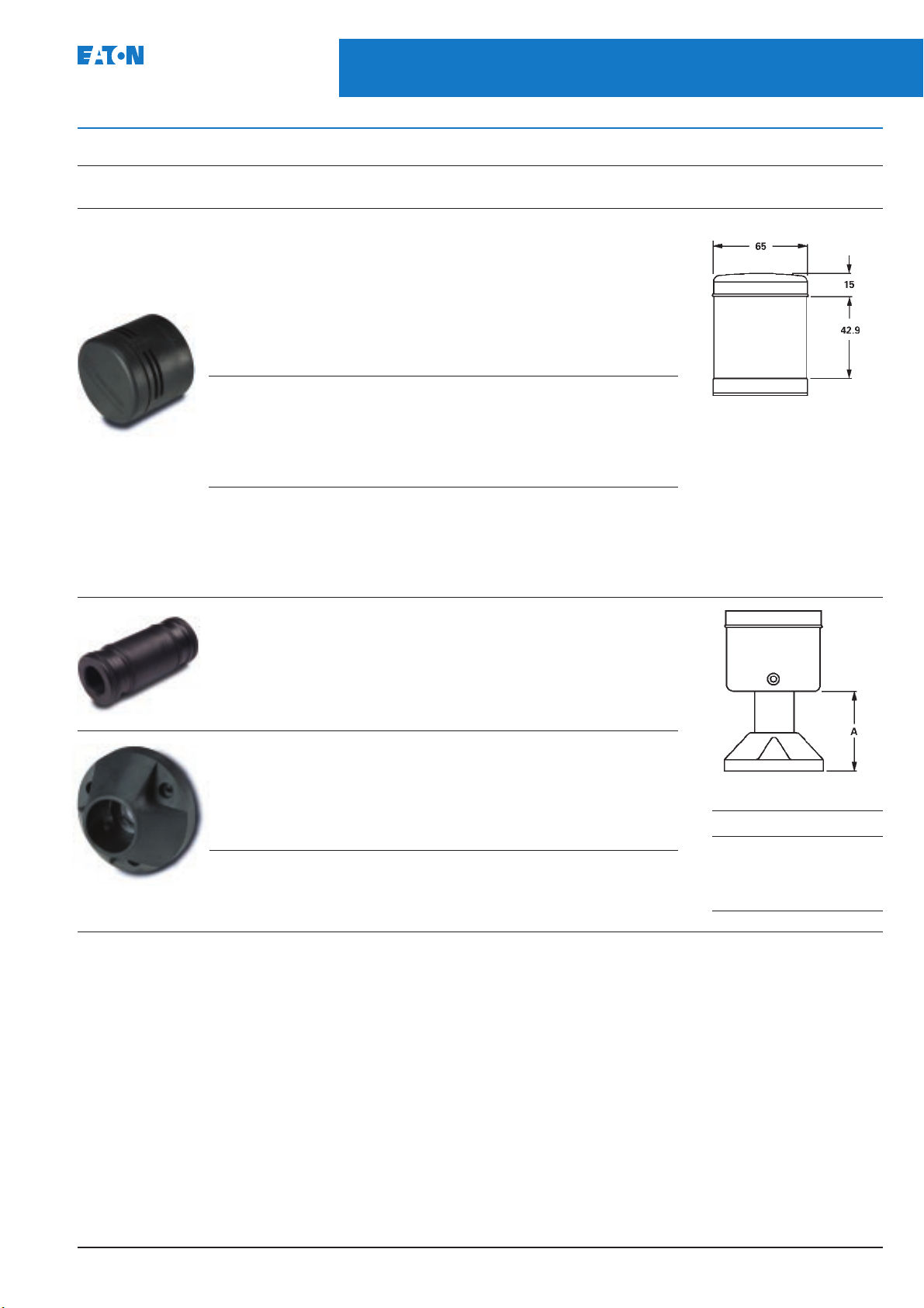
August 2004
Accessories (continued)
Description Voltage Catalogue Approximate dimensions (mm)
Audible alarms – IP20
Volume adjustment range:
64 dB to 90 dB typical current draw (mA):
Mono-tonal
4.5 mA 12V ac/dc E26BQV1
12.6 mA 24V ac/dc E26BQV2
9.4 mA 48V ac/dc E26BQV3
11.5 mA 120V ac/dc E26BQV4
5.1 mA 240V ac/dc E26BQV5
Bi-Tonal
4.5 mA 12V ac/dc E26BNV1
12.6 mA 24V ac/dc E26BNV2
9.4 mA 48V ac/dc E26BNV3
11.5 mA 120V ac/dc E26BNV4
5.1 mA 240V ac/dc E26BNV5
Intermittent
4.5 mA 12V ac/dc E26BPV1
12.6 mA 24V ac/dc E26BPV2
9.4 mA 48V ac/dc E26BPV3
11.5 mA 120V ac/dc E26BPV4
5.1 mA 240V ac/dc E26BPV5
Extension tubes – Black anodised aluminium
For use with standard mounting base or 3/4" NPT threaded hub –
Extension “A”:
20 mm extension – E26BHA
160 mm extension – E26BJA
360 mm extension – E26BKA
760 mm extension – E26BMA
Mounting bases
Standard 3-hole mounting base – E26S108
Stacklights
51
E26 Series - Accessories
numbers
Standard 4-hole mounting base – E26S109
Assembled dimensions (mm)
Tube extension Height A
20 45
160 185
360 385
760 785
PGO4700001U
Page 52

52
Stacklights
E26 Series - Accessories
Accessories (continued)
Description Notes Diagram Catalogue
numbers
Replacement Normally included 9 E26S105
mounting gasket with Stacklight base
Replacement Normally included 2 E26S106
lens O-ring with light modules
Replacement Normally included 6 E26S107
extension with extension tubes
tube O-rings
Replacement Normally included 1 E26S68
cover with Stacklight base
Replacement 12V 5 E26S8
lamps 24V E26S9
48V E26S10
120V E26S11
240V E26S12
Replacement 12V ac/dc 4 E26S33
Xenon strobe 24V ac/dc E26S34
dual high (Does 48V ac/dc E26S35
not include 120V ac E26S36
lenses) 240V ac E26S37
Replacement Clear 3 E26S38
lenses Red E26S39
Green E26S40
Yellow E26S41
Blue E26S42
Amber E26S43
Replacement White – normally 4 E26S31
diffusers supplied with
incandescent light
modules
Clear – normally 4 E26S32
supplied with LED
light modules
Lamp removal For E26 and E22 E22BA3
tool incandescent lamps
August 2004
Typical Stacklight assemblies
(exploded view
PGO4700001U
Page 53

Stacklights
August 2004
E26 Series - LEDs - cluster or cylindrical
LEDs – Cluster or cylindrical
Voltage Colour Catalogue numbers
Cluster LEDs Cylindrical LEDs
Steady Flashing Steady Only
12V ac/dc Red E26S15 E26S48 E26S110
Green E26S19 E26S53 E26S114
Yellow E26S23 E26S58 E26S112
Blue E26S27 E26S63 E26S115
White E26S71 E26S75 E26S116
Amber E26S79 E26S84 E26S111
24V ac/dc Red E26S16 E26S49 E26S117
Green E26S20 E26S54 E26S121
Yellow E26S24 E26S59 E26S119
Blue E26S28 E26S64 E26S122
White E26S72 E26S76 E26S123
Amber E26S80 E26S85 E26S118
48V ac/dc Red E26S17 E26S50 E26S124
Green E26S21 E26S55 E26S128
Yellow E26S25 E26S60 E26S126
Blue E26S29 E26S65 E26S129
White E26S73 E26S77 E26S130
Amber E26S81 E26S86 E26S125
120V ac/dc Red E26S18 E26S51 E26S138
Green E26S22 E26S56 E26S142
Yellow E26S26 E26S61 E26S140
Blue E26S30 E26S66 E26S143
White E26S74 E26S78 –
Amber E26S82 E26S87 E26S139
240V ac/dc Red E26S44 E26S52 –
Green E26S45 E26S57 –
Yellow E26S46 E26S62 –
Blue E26S47 E26S67 –
White E26S101 E26S102 –
Amber E26S83 E26S88 –
53
PGO4700001U
Page 54

54
Stacklights
August 2004
E26 Series - Technical and application data
Technical data
Standards and certifications
CE 60947-5-1
UL 508 – file #E131568
cUL C22.2 No. 14 – file #E131568
Ingress protection
Stacklight base and light units: IP65, NEMA 4, 4X and 13
Alarm units: IP20, NEMA 1
Electrical shock protection
Stacklight base and light unit: IP2X
Alarm units: IP0X
Mechanical ratings
Shock (IEC 68-2-27): 11 mS, 15g
Vibration (IEC 68-2-6): 10 sweeps 10 to 150 Hz, 2g
Bump (IEC 68-2-29): 1000 pulses, 6 mS, 15g
Climate conditions
Operating: maximum 40°C at 95% RH,
temperature –20° to 60°C
Storage: Temperature –40° to 80°C
Materials
Cover: Polycarbonate
Lenses: Polycarbonate
Stacklight base: Nylon
Extension tubes: Aluminium
Mounting base: Zinc die cast
Terminals
2.5 – 0.05 mm
for two conductors of the same size. Do not mix solid and
stranded wire in the same terminal.
Recommended tightening torque is 0.5 – 0.6 Nm.
Electrical ratings
Insulation voltage (Ui): 690V
Operational voltage (Ue): 250V
Impulse withstand voltage (Uimp): 1.5 kV
Bulb specifications
Incandescent lamp type: BA15d
Maximum lamp wattage: 6W
Bulbs – average life:
Incandescent: 7,000 to 12,000 hrs.
Xenon flasher: 20,000 hrs.
LED: 60,000 to 100,000 hrs.
LED/Incandescent comparison
Incandescent lamps
Average operating life of 7,000 hours
Each lamp can be used with any colour lens
Low cost results in short term savings
LED lamps
Average operating life of 100,000 hours
Low power consumption
Extended life results in long-term savings
2
for single conductors and 0.75 – 0.14 mm
Application data
E26 Stacklight incandescent lamps
Type Lamp Approximate Theoretical
of light used current, mA lamp life, hours
12V BA15d 417 7,000
24V BA15d 208 7,000
48V BA15d 104 7,000
110 – 140V BA15d 36 – 50 7,000
220 – 260V BA15d 23 – 27 12,000
E26 Xenon flasher
Model Voltage Current (cont.) Lamp life
12V DC 460 mA 20,000
24V Strobe DC 190 mA 20,000
48V DC 100 mA 20,000
120V AC 60 mA ➀ 20,000
240V AC 30 mA ➀ 20,000
➀ Represents average current draw, 1.6A peak for 120V and 0.8 peak at 240V.
E26 Continuous/flashing Stacklight LED
Type Colour Cluster LED Cylindrical LED Theoretical
of Approximate Approximate lamp life, hours
2
light current, mA current, mA as applied
12V Red 92 92 100,000
ac/dc Amber 92 92 100,000
Yellow 92 92 100,000
Green 60 60 80,000
Blue 60 60 60,000
White 60 60 60,000
24V Red 47 47 100,000
ac/dc Amber 47 47 100,000
Yellow 47 47 100,000
Green 59 59 80,000
Blue 59 59 60,000
White 59 59 60,000
48V Red 25 25 100,000
ac/dc Amber 25 25 100,000
Yellow 25 25 100,000
Green 18 18 80,000
Blue 31 31 60,000
White 31 31 60,000
60V Red 25 25 100,000
ac/dc Amber 25 25 100,000
Yellow 25 25 100,000
Green 18 18 80,000
Blue 17 17 60,000
White 17 17 60,000
120V Red 24 24 100,000
ac/dc Amber 24 24 100,000
Yellow 24 24 100,000
Green 17 17 80,000
Blue 16 16 60,000
White 16 16 60,000
Note:
Published theoretical lamp lives are based on ideal laboratory conditions and
should be used for comparison only. Actual life may be shorter due to various
application conditions.
AC 780 mA 20,000
AC 320 mA 20,000
AC 150 mA 20,000
at rated volts at rated volts
per light as applied
PGO4700001U
Page 55

Stacklights
August 2004
E26 Series - Mounting options and dimensions
Mounting options and dimensions (mm)
55
Stacklight bases may be mounted without the use
of extension tube or mounting base. If additional
height is required, choose 20 to 760 mm extension
tubes that fit between the mounting base and the
Base mounting
Stacklight base. The extension tubes are threaded
with 3/4" NPT threads, allowing for direct
connection to conduit fittings or threaded holes
without the use of a mounting base.
Utilising extension tube
and mounting base
Base mounting
Note
➀ Stacklight base and gasket are supplied as standard with two sets of base mount holes.
One set with centre-to-centre spacing of 44.5 mm and another set with centre-to-centre spacing of 42 mm.
3-hole mounting for E26S108
4-hole mounting for E26S109
PGO4700001U
Page 56

56
Stacklights
E26 Series - Dimensions
Approximate dimensions (mm)
August 2004
One-light unit Stacklight
Standard With alarm With Xenon flasher
Two-light unit Stacklight
Standard With alarm With Xenon flasher
Light modules
Standard
Xenon
Note
➀Cover included with Stacklight base.
Three-light unit Stacklight
Standard With alarm With Xenon flasher
PGO4700001U
Page 57

 Loading...