

Cutler-Hammer 50 VCP-T25, 50 VCP-TR25, 75 VCP-T16, 75 VCP-TR16, 75 VCP-TR20 Instructions For The Use, Operation And Maintenance
...
I.B. 69C3067H06
Effective February 2003 Supersedes I.B. 69C3067H05 dated March 2002
Cutler-Hammer
Instructions for the Use, Operation and Maintenance of
Types VCP-T and VCP-TR Vacuum Circuit Breakers
VCP-T Drawout
(with or without trip unit - shown with Digitrip Trip Unit)
VCP-TR Fixed
(with or without trip unit - non-automatic shown)
Courtesy of NationalSwitchgear.com

Courtesy of NationalSwitchgear.com

I.B. 69C3067H06
Page iii
Effective 2/03
All possible contingencies which may arise during installation, operation or maintenance, and all details and
variations of this equipment do no purport to be covered by these instructions. If further information is
desired by purchaser regarding his particular installation, operation or maintenance of particular equipment,
contact a Cutler-Hammer representative.
IMPROPERLY INSTALLING OR MAINTAINING
THESE PRODUCTS CAN RESULT IN DEATH, SERI-
OUS PERSONAL INJURY, OR PROPERTY DAMAGE.
READ AND UNDERSTAND THESE INSTRUCTIONS
BEFORE ATTEMPTING ANY UNPACKING, ASSEM-
BLY, OPERATION OR MAINTENANCE OF THE CIR-
CUIT BREAKERS.
INSTALLATION OR MAINTENANCE SHOULD BE
ATTEMPTED ONLY BY QUALIFIED PERSONNEL.
THIS INSTRUCTION BOOK SHOULD NOT BE CON-
SIDERED ALL INCLUSIVE REGARDING INSTALLA-
TION OR MAINTENANCE PROCEDURES. IF FUR-
THER INFORMATION IS REQUIRED, YOU SHOULD
CONTACT CUTLER-HAMMER
!
WARNING
THE CIRCUIT BREAKER ELEMENTS DESCRIBED IN
THIS BOOK ARE DESIGNED AND TESTED TO
OPERATE WITHIN THEIR NAMEPLATE RATINGS.
OPERATION OUTSIDE OF THESE RATINGS MAY
CAUSE THE EQUIPMENT TO FAIL, RESULTING IN
DEATH, BODILY INJURY AND PROPERTY DAMAGE.
ALL SAFETY CODES, SAFETY STANDARDS
AND/OR REGULATIONS AS THEY MAY BE APPLIED
TO THIS TYPE OF EQUIPMENT MUST BE STRICTLY
ADHERED TO.
SERIOUS INJURY, INCLUDING DEATH, CAN
RESULT FROM FAILURE TO FOLLOW THE PROCE-
DURES OUTLINED IN THIS MANUAL. THESE CIR-
CUIT BREAKER ELEMENTS ARE SOLD PURSUANT
TO A NON-STANDARD PURCHASING AGREEMENT
WHICH LIMITS THE LIABILITY OF THE MANUFAC-
TURER.
!
WARNING
Cutler-Hammer
Pittsburgh, PA 15220
Courtesy of NationalSwitchgear.com

TABLE OF CONTENTS
Page
SECTION 1: INTRODUCTION
1-1 VCP-T and VCP-TR Vacuum Circuit Breaker Ratings....................................................................................................................................1
1-2 Types VCP-T and VCP-TR Outlines and Dimensions....................................................................................................................................2
SECTION 2: SAFE PRACTICES
SECTION 3: RECEIVING, HANDLING AND STORAGE
3-1 Receiving.......................................................................................................................................................................................................11
3-2 Handling ........................................................................................................................................................................................................11
3-2.1 Unpacking ....................................................................................................................................................................................11
3-2.2 Lifting ...........................................................................................................................................................................................11
3-3 Storage .........................................................................................................................................................................................................12
3-4 Typical Breaker and Cassette Weights.........................................................................................................................................................12
SECTION 4: INSTALLATION AND WIRING
4-1 Initial Inspection ...........................................................................................................................................................................................20
4-2 Electrical Clearances ...................................................................................................................................................................................20
4-3 Interphase Barriers........................................................................................................................................................................................20
4-4 Front Cover ..................................................................................................................................................................................................20
4-5 Installing Fixed Circuit Breaker .....................................................................................................................................................................20
4-5.1 Fixed Mechanical Interfaces ........................................................................................................................................................20
4-5.2 Fixed Electrical Interfaces ............................................................................................................................................................20
4-6 Installing Drawout Circuit Breaker.................................................................................................................................................................21
4-6.1 Drawout Mechanical Interfaces ....................................................................................................................................................21
4-6.2 Circuit Breaker Positioning ...........................................................................................................................................................22
4-6.3 Drawout Electrical Interfaces .......................................................................................................................................................24
4-6.4 Levering Circuit Breaker ...............................................................................................................................................................26
SECTION 5: DESCRIPTION AND OPERATION
5-1 Introduction ...................................................................................................................................................................................................29
5-2 Vacuum Interrupter Assembly ......................................................................................................................................................................29
5-2.1 Contact Erosion Indicator..............................................................................................................................................................32
5-2.2 Contact Wipe and Stroke..............................................................................................................................................................32
5-3 Stored Energy Mechanism ...........................................................................................................................................................................33
5-3.1 Manual Operation ........................................................................................................................................................................33
5-3.2 Electrical Operation ......................................................................................................................................................................34
5-3.3 Trip Free Operation ......................................................................................................................................................................34
5-3.4 Anti-Pump Feature .......................................................................................................................................................................34
5-3.5 Latch Check Switch ......................................................................................................................................................................34
5-3.6 Mechanical Interlocks ...................................................................................................................................................................34
5-4 Connection Diagrams....................................................................................................................................................................................35
5-4.1 Timing...........................................................................................................................................................................................35
5-4.2 Secondary Connections................................................................................................................................................................35
5-5 Electronic Tripping System ...........................................................................................................................................................................41
5-5.1 Microprocessor-Based Trip Unit ...................................................................................................................................................41
5-5.2 Rating Plug ...................................................................................................................................................................................42
5-5.3 Current Sensors............................................................................................................................................................................42
5-5.4 Trip Actuator .................................................................................................................................................................................42
5-6 Accessory Devices........................................................................................................................................................................................43
5-6.1 Plug-in Electrical Accessories.......................................................................................................................................................43
5-6.2 Internal Electrical Accessories......................................................................................................................................................44
5-6.3 Mechanical Accessories ..............................................................................................................................................................46
SECTION 6: INSPECTION AND MAINTENANCE
6-1 Introduction ...................................................................................................................................................................................................47
6-2 Frequency of Inspection and Maintenance...................................................................................................................................................47
I.B. 69C3067H06
Page iv
Effective 2/03
Courtesy of NationalSwitchgear.com

I.B. 69C3067H06
Page v
6-3 Vacuum Interrupter Integrity Test..................................................................................................................................................................47
6-4 Contact Erosion.............................................................................................................................................................................................49
6-5 Contact Wipe.................................................................................................................................................................................................49
6-6 Insulation ......................................................................................................................................................................................................51
6-7 Insulation Integrity Check..............................................................................................................................................................................51
6-8 Primary Circuit Resistance Check ................................................................................................................................................................51
6-9 Mechanism Check ........................................................................................................................................................................................51
6-10 Lubrication ....................................................................................................................................................................................................51
6-11 Troubleshooting ............................................................................................................................................................................................51
SECTION 7: RENEWAL PARTS
7-1 General ......................................................................................................................................................................................................56
7-2 Ordering Instructions.....................................................................................................................................................................................56
7-3 Mechanism and Related Parts......................................................................................................................................................................57
7-4 Current Path..................................................................................................................................................................................................58
7-5 Electrical Attachments...................................................................................................................................................................................59
7-6 Other Breaker Related Parts.........................................................................................................................................................................62
7-7 Trip Unit and Related Parts...........................................................................................................................................................................63
LIST OF FIGURES
Figure Title Page
1-1 VCP-TR Fixed Breaker 4.76/8.25kV, 600A/800A, 16kA, 60kV BIL Only Outlines..............................................................................2
1-2 All VCP-TR Fixed (except 4.76/8.25kV, 600/800A, 16kA, 60kV BIL see Figure 1-1) Outlines ................................................................3
1-3 VCP-T Drawout Breaker 4.76/8.25kV Outlines Outlines ....................................................................................................................4
1-4 VCP-T Drawout Breaker 4.76/8.25kV Outlines ..................................................................................................................................5
1-5 VCP-T Drawout Breaker 8.25/15kV Outlines .....................................................................................................................................6
1-6 VCP-T Breaker Cassette Up to 95kV BIL Outlines ............................................................................................................................7
1-7 VCP-T Breaker Cassette 60kV BIL Outlines ......................................................................................................................................8
1-8 VCP-T Breaker Cassette 60 & 95kV BIL Outlines .............................................................................................................................9
3-1 Fixed Breaker Shown Mounted on Pallet..........................................................................................................................................11
3-2 Keyed Shipping Clamp Being Removed from Fixed Breaker...........................................................................................................12
3-3 Front and Rear Views VCP-TR Fixed (4.76 and 8.25kV, 600/800A, 16kA, 60kV BIL).....................................................................13
3-4 Front and Rear Views All VCP-TR Fixed (except 4.76 and 8.25kV, 600/800A, 16kA, see Figure 3-3)............................................14
3-5 Front and Rear Views VCP-T Drawout (4.76 and 8.25kV, 600/800A, 16kA, 60kV BIL)...................................................................15
3-6 Front and Rear Views All VCP-T Drawout (except 4.76/8.25kV, 630/800A, 16kA, 60kV BIL see Figure 3-5) .................................16
3-7 Front and Rear Views Drawout Cassette (For use with 60kV BIL Drawout Breakers Only).............................................................17
3-8 Front and Rear Views Drawout Cassette (For use with all 95kV BIL Drawout Breakers).................................................................18
3-9 Typical VCP-T Front Cover...............................................................................................................................................................19
4-1 Typical Fixed Non-Automatic VCP-TR 15KV Circuit Breaker...........................................................................................................21
4-2 Bottom View of VCP-TR Circuit Breaker showing Mounting Holes ..................................................................................................21
4-3 Cassette Rejection Interlock Pin Positioning ....................................................................................................................................22
4-4 Positioning Circuit Breaker with Lifter...............................................................................................................................................23
4-5 Breaker Shoot Bolts Against Cassette..............................................................................................................................................23
4-6 Shoot Bolt Handle in Up (Locked) Position.......................................................................................................................................23
4-7 Shoot Bolt Handle Shown in Position “C” - Shoot Bolts Protrude Fully from Cradle.........................................................................24
4-8 Shoot Bolt Handle Shown in Position “B” - Shoot Bolts Protrude Partially from Cradle....................................................................24
4-9 Shoot Bolt Handle Shown in Position “A” - Shoot Bolts Retracted Fully Inside Cradle.....................................................................24
4-10 Circuit Breaker Umbilical Cord Shown Connected to Breaker Prior to Breaker Insertion.................................................................25
4-11 Secondary Connector Viewed from Rear of Breaker........................................................................................................................25
4-12 Cassette Secondary Connector and Interlock Lever ........................................................................................................................25
4-13 Drawout Cassette with Primary Safety Shutters Open Showing Fixed Primary Stabs.....................................................................26
4-14 Circuit Breaker Shown in Levered Out (DISCONNECT) Position - Correct for Breaker Positioning................................................26
4-15 Circuit Breaker Shown in Levered In (CONNECT) Position - Incorrect for Breaker Positioning.......................................................26
Courtesy of NationalSwitchgear.com

I.B. 69C3067H06
Page vi
Effective 2/03
4-16 Cradle Mounted Levering Mechanism..............................................................................................................................................27
4-17 Levering Circuit Breaker ...................................................................................................................................................................27
4-18 Circuit Breaker Connected as Indicated by Fully Connected Position Label....................................................................................27
4-19 Circuit Breaker Shown in CONNECT Position with Secondary Connections Made.........................................................................28
4-20 Primary Safety Shutters Shown in Open Position with Fixed Primary Stabs Exposed.....................................................................28
4-21 Padlocking Device on Side of Cassette............................................................................................................................................28
5-1 Rigid Frame Construction ................................................................................................................................................................29
5-2 VCP-TR Fixed Non-automatic Circuit Breaker (Front Cover Removed)...........................................................................................30
5-3 VCP-T Drawout Circuit Breaker (Front Cover Removed).................................................................................................................31
5-4 Fixed 50 VCP-TR Interrupter Assembly (600/800A, 16kA shown)...................................................................................................32
5-5 Drawout 150 VCP-T Interrupter Assemblies (1200A, 25kA shown) .................................................................................................32
5-6 Breaker Closing Springs Being Manually Charged...........................................................................................................................33
5-7 Motor Operator Shown Installed ......................................................................................................................................................34
5-8 Typical Cover Mounted Key Interlock ..............................................................................................................................................34
5-9 Typical Mechanical Cable Interlock ..................................................................................................................................................35
5-10 VCP-T and VCP-TR Non Trip Unit Connection Diagram..................................................................................................................36
5-11 VCP-T and VCP-TR with 520V Trip Unit Connection Diagram.........................................................................................................37
5-12 VCP-T and VCP-TR with 1150V Trip Unit Connection Diagram.......................................................................................................38
5-13 VCP-T Drawout Umbilical Cord and Connector Wiring Diagram......................................................................................................39
5-14 Secondary Protective Hood..............................................................................................................................................................35
5-15 Top View Secondary Connectors ....................................................................................................................................................40
5-16 Secondary Male Connector with Female Pins..................................................................................................................................40
5-17 Optional Terminal Block ...................................................................................................................................................................40
5-18 AMP Secondary Wiring Removal Tool (AMP#305183) (C-H#MAMPSEC) ......................................................................................40
5-19 Digitrip RMS 1150Vi Programmable Trip Unit Installed in T-VAC Circuit Breaker............................................................................41
5-20 Hand Held Tester..............................................................................................................................................................................41
5-21 Through-The-Window Electrical Accessories...................................................................................................................................43
5-22 Shunt Trip Device .............................................................................................................................................................................43
5-23 Spring Release Device .....................................................................................................................................................................43
5-24 Undervoltage Release Device ..........................................................................................................................................................44
5-25 Rugged Motor Operator....................................................................................................................................................................45
5-26 Auxiliary Switch ................................................................................................................................................................................45
5-27 Pushbutton Cover Mounted .............................................................................................................................................................46
5-28 Door Escutcheon and Gasket...........................................................................................................................................................46
6-1 Contact Erosion Mark Visible on Stem ............................................................................................................................................50
6-2 Contact Wipe Inspection Area .........................................................................................................................................................50
6-3 Satisfactory Contact Wipe Condition with Breaker Closed .............................................................................................................50
6-4 Unsatisfactory Contact Wipe Condition with Breaker Closed .........................................................................................................50
6-5 Circuit Breaker Lubrication ...............................................................................................................................................................54
6-6 Drawout Cassette Lubrication ..........................................................................................................................................................55
LIST OF TABLES
Table Title Page
1.1 VCP-T and VCP-TR Ratings ..............................................................................................................................................................1
3.1 Circuit Breaker and Cassette Weights..............................................................................................................................................12
4.1 Cassette Rejection Interlock Pin Locations.......................................................................................................................................21
5.1 Digitrip Trip Units .............................................................................................................................................................................41
5.2 Current Sensors and Matching Rating Plugs ...................................................................................................................................42
5.3 Shunt Trip Ratings ...........................................................................................................................................................................44
5.4 Spring Release Ratings ....................................................................................................................................................................44
5.5 Undervoltage Release Ratings .........................................................................................................................................................44
5.6 Motor Operator Ratings ....................................................................................................................................................................45
5.7 Auxiliary Switch Contacts Interrupting Capacities.............................................................................................................................45
6.1 Inspection and Maintenance Procedures .........................................................................................................................................48
6.2 Test Voltage......................................................................................................................................................................................49
6.3 Typical Resistance Measurements...................................................................................................................................................51
6.4 Troubleshooting Guide......................................................................................................................................................................52
Courtesy of NationalSwitchgear.com

I.B. 69C3067H06
Page 1
Effective 2/03
SECTION 1: INTRODUCTION
The purpose of this book is to provide instructions for
unpacking, storage, use, operation and maintenance of
VCP-T drawout type and VCP-TR fixed type Vacuum
Circuit Breakers. VCP-T and VCP-TR are compact vac-
uum interrupting elements designed for applications
such as: mine power centers, portable power substa-
tions, fixed breaker or drawout switchgear and portable
generators, all without compromising metal clad expec-
tations. VCP-T and VCP-TR breakers were specifically
designed to provide proven reliable performance in a
small package. The circuit breakers are available in volt-
age classes of 4.76, 8.25 and 15.0 kV. They are tested
in accordance with ANSI C37.04 and C37.09 (Table
1.1).
1-1 T-VAC and T-VACR Vacuum Breaker Ratings
Refer to Table 1.1
The circuit breaker's nameplate provides complete rat-
ing information. Reliable control and protection for medi-
um voltage equipment and circuits are achieved through
the use of VCP-T and VCP-TR Vacuum Breakers.
SATISFACTORY PERFORMANCE OF THESE
BREAKERS IS CONTINGENT UPON PROPER APPLI-
CATION, CORRECT INSTALLATION AND ADE-
QUATE MAINTENANCE. THIS INSTRUCTION BOOK
MUST BE CAREFULLY READ AND FOLLOWED IN
ORDER TO OBTAIN OPTIMUM PERFORMANCE FOR
LONG USEFUL LIFE OF THE CIRCUIT BREAKERS.
VCP-T and VCP-TR CIRCUIT BREAKERS ARE PRO-
TECTIVE DEVICES, AS SUCH, THEY ARE MAXIMUM
RATED DEVICES. THEREFORE, THEY SHOULD NOT
UNDER ANY CIRCUMSTANCES BE APPLIED OUT-
SIDE THEIR NAMEPLATE RATINGS.
!
WARNING
Table 1.1 VCP-T and VCP-TR Ratings (ANSI C37.04 and C37.09)
Identification Rated Values
Circuit
Breaker
Type
50 VCP-T16
and
50 VCP-TR16
50 VCP-T20
and
50 VCP-TR20
50 VCP-T25
and
50 VCP-TR25
75 VCP-T16
and
75 VCP-TR16
75 VCP-T20
and
75 VCP-TR20
75 VCP-T25
and
75 VCP-TR25
150 VCP-T16
and
150 VCP-TR16
150 VCP-T20
and
150 VCP-TR20
150 VCP-T25
and
150 VCP-TR25
Voltage
Class
kV rms
4.76
4.76
4.76
8.25
8.25
8.25
15
15
15
Short Circuit
➂
Breaking
Current
kA rms
16
20
25
16
20
25
16
20
25
Short Circuit
Making
Current
kA Peak
42
52
65
42
52
65
42
52
65
Mechanical
Endurance
C - O
Operations
20000
20000
10000
10000
10000
10000
10000
10000
10000
10000
10000
10000
20000
20000
10000
10000
10000
10000
10000
10000
10000
10000
10000
10000
10000
10000
10000
10000
10000
10000
10000
10000
10000
10000
10000
10000
Continuous
Current
Amperes
600
800
1200
1600
➁
600
800
1200
1600
➁
600
800
1200
1600
➁
600
800
1200
1600
➁
600
800
1200
1600
➁
600
800
1200
1600
➁
600
800
1200
1600
➁
600
800
1200
1600
➁
600
800
1200
1600
➁
Power
Frequency
kV rms
19
19
19
20
20
20
36
36
36
Impulse
Withstand
kV Peak
60
60
60
60
➀
60
➀
60
➀
95
95
95
Insulation Level
➀
Use 15kV Breaker and Cassette when 95kV Impulse Withstand required ➁1600A VCP-T Breaker not available
➂
Also 2 Second Short Time Current Rating
Courtesy of NationalSwitchgear.com

I.B. 69C3067H06
Page 2
Effective 2/03
Figure 1-1 VCP-TR Fixed Breaker 4.76/8.25kV, 600A/800A, 16kA, 60kV BIL Only Outlines in inches [mm]
1-2 Types VCP-T and VCP-TR Outlines and Dimensions (Circuit Breakers and Drawout Cassettes)
Courtesy of NationalSwitchgear.com

I.B. 69C3067H06
Page 3
Effective 2/03
Figure 1-2 All VCP-TR Fixed (except 4.76/8.25kV, 600/800A, 16kA, 60kV BIL see Figure 1-1) Outlines in inches [mm]
Vertical
Barriers (2)
95kV BIL Only
Horizontal
Barriers (3)
95kV BIL
Only
Courtesy of NationalSwitchgear.com

I.B. 69C3067H06
Page 4
Effective 2/03
Figure 1-3 VCP-T Drawout Breaker 4.76/8.25kV Outlines in inches [mm] (Refer to above Applicable Ratings Table)
Applicable Ratings
kV 16kA
4.76/8.25kV 600A
60kV BIL 800A
Courtesy of NationalSwitchgear.com

I.B. 69C3067H06
Page 5
Effective 2/03
Figure 1-4 VCP-T Drawout Breaker 4.76/8.25kV Outlines in inches [mm] (Refer to above Applicable Ratings Table)
Applicable Ratings
kV 16kA 20kA 25kA
4.76/8.25kV NA 600A 600A
60kV BIL NA 800A 800A
1200A 1200A 1200A
Courtesy of NationalSwitchgear.com

I.B. 69C3067H06
Page 6
Effective 2/03
Figure 1-5 VCP-T Drawout Breaker 8.25/15kV Outlines in inches [mm] (Refer to above Applicable Ratings Table)
Applicable Ratings
kV 16kA 20kA 25kA
8.25/15kV 600A 600A 600A
All 95kV BIL 800A 800A 800A
1200A 1200A 1200A
1200A
Courtesy of NationalSwitchgear.com

I.B. 69C3067H06
Page 7
Effective 2/03
Figure 1-6 VCP-T Breaker Cassette Up to 95kV BIL Outlines in inches [mm] (Additional Details Figures 1-7 &1-8)
Breaker Shown in Fully
Connected Position
Breaker Shown in
Disconnected Position
Barrier Shown not
Applicable to 60kV BIL
Breaker
Courtesy of NationalSwitchgear.com
I.B. 69C3067H06
Page 8
Effective 2/03
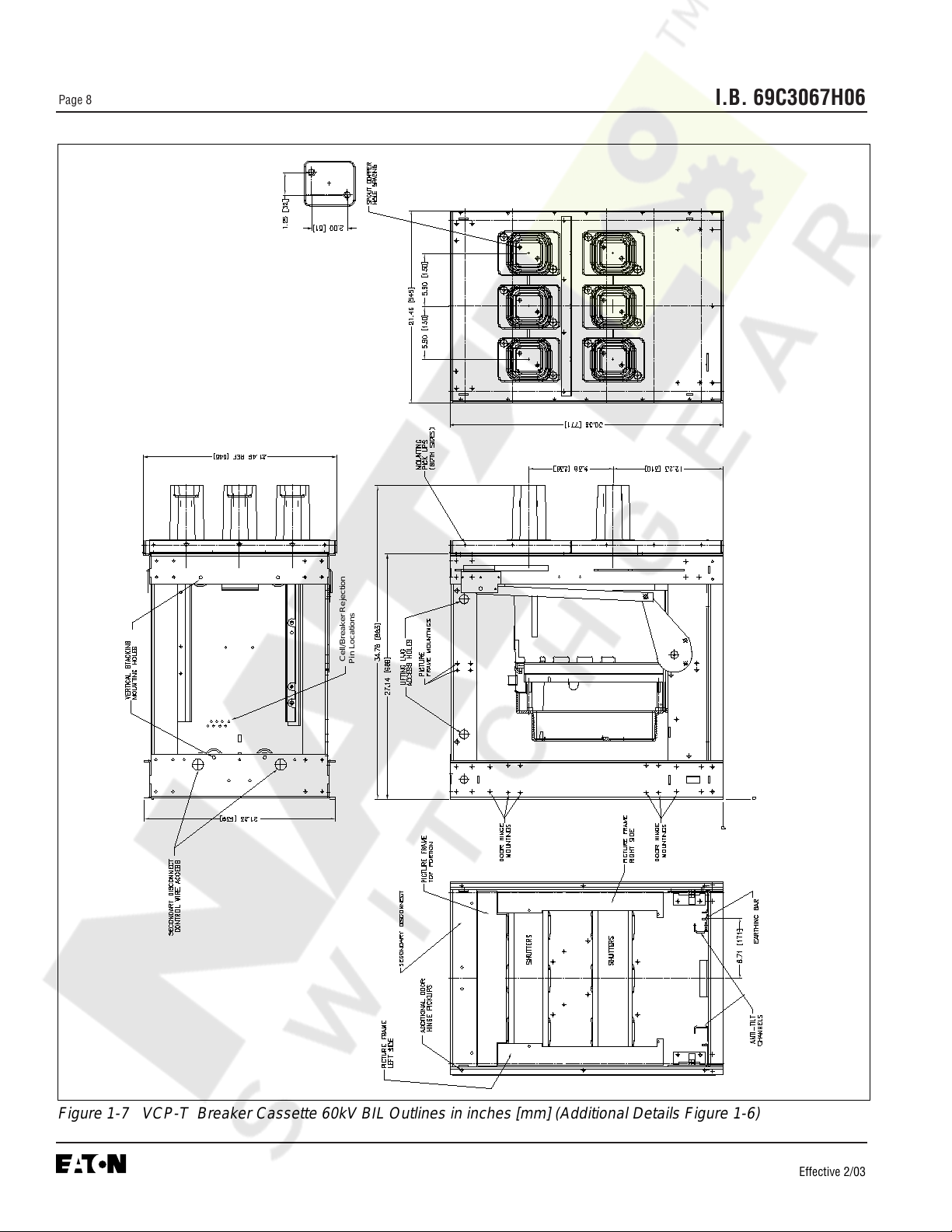
Figure 1-7 VCP-T Breaker Cassette 60kV BIL Outlines in inches [mm] (Additional Details Figure 1-6)
Cell/Breaker Rejection
Pin Locations
Courtesy of NationalSwitchgear.com

I.B. 69C3067H06
Page 9
Effective 2/03
Figure 1-8 VCP-T Breaker Cassette 95kV BIL Outlines in inches [mm] (Additional Details Figure 1-6)
75 & 95kV BIL
95kV BIL
Only
Multi-Layer
Glass Polyester
insulating
B-Plane Insert
Dimensional View
Cell/Breaker
Rejection Pin
Locations
Courtesy of NationalSwitchgear.com

I.B. 69C3067H06
Page 10
Effective 2/03
SECTION 2: SAFE PRACTICES
The circuit breakers are equipped with high speed, high
energy operating mechanisms. They are designed with
built-in safety interlocks to provide for safe operation. In
addition, other optional interlocks are available depend-
ing upon the application. Refer to Section 5 for addition-
al interlock information. It is the customers’ responsibility
to insure that appropriate interfaces with the breakers
are provided and tests conducted to adequately prove
proper installation and functioning.
TO PROTECT THE PERSONNEL ASSOCIATED WITH
INSTALLATION, OPERATION, AND MAINTENANCE
OF THESE BREAKERS, THE FOLLOWING PRAC-
TICES MUST BE FOLLOWED:
• Only qualified persons, as defined in the Local
Electrical Codes, who are familiar with the
installation and maintenance of medium voltage
circuits and equipment, should be permitted to work
on these breakers.
• Read these instructions carefully before attempting
any installation, operation or maintenance of these
breakers.
• Always remove drawout type breakers from their
enclosure before performing any maintenance.
Failure to do so could result in electrical shock lead-
ing to death, severe personal injury and/or property
damage.
• Always make sure that primary and secondary
power are disconnected from a fixed breaker before
performing any maintenance. Failure to do so could
result in electrical shock leading to death, severe
personal injury and/or property damage.
• Do not work on a closed breaker or a breaker with
closing springs charged. The closing springs should
be discharged and the main contacts open before
working on the breaker. Failure to do so could result
in cutting or crushing injuries.
• Do not use a circuit breaker by itself as the sole
means of isolating a high voltage circuit. As
appropriate, use an isolation means and follow all
lock-out and tagging rules of the Local Electrical
Codes and any and all applicable codes, regulations
and work rules.
• Always ensure that drawout circuit breakers are in
one of their designed cell positions, such as
Connect, Test/Disconnect or Remove. A circuit
breaker permitted to remain in an intermediate posi-
tion could result in control circuits being improperly
connected resulting in electrical failures.
• Breakers are equipped with safety interlocks.
Do Not defeat them. This may result in death, bodi-
ly injury and/or equipment damage.
• Do not work on a circuit breaker while suspended
from a lifting means. Maintenance work should be
performed on a properly supported cart or table.
WARNING
Courtesy of NationalSwitchgear.com
!

I.B. 69C3067H06
Page 11
Effective 2/03
and understand the directions. Unpacking a fixed circuit
breaker is described in the next paragragh in detail.
Upacking a drawout circuit breaker is also simple to
accomplish and is not described here in detail. Just pro-
ceed by carefully removing all packing material used for
protection during shipment and the fasteners used to
secure the drawout circuit breaker to its shipping pallet.
When ready to inspect and install the circuit breaker,
carefully remove any banding straps and lift off the card-
board box. Remove any additional packing material and
internally packed documentation. The circuit breaker is
mounted to a wooden shipping pallet. A keyed metal
clamp is used on each side of the circuit breaker to hold
it to the wooden pallet (Figure 3-1). Remove the screws
from the wooden pallet on each side and lift up and out
on the keyed metal clamps for removal (Figure 3-2). The
circuit breaker is now ready to be removed from its ship-
ping pallet. Save all shipping hardware and packaging
material for any future shipments of the circuit breaker.
3-2.2 LIFTING
To closely examine, install or just become familiar with
the circuit breaker, carefully lift and place the circuit
breaker on a solid work surface capable of handling the
circuit breaker's weight (Table 3.1). The circuit breaker
is provided with two integrally mounted lifting hooks for
use with a standard sling (Figure 3-1). Once the sling is
properly placed, the breaker can be carefully lifted and
moved using an overhead lifter or portable floor lifter.
Every effort should be made to minimize circuit breaker
swing or tilt.
Figure 3-1 Fixed Breaker Shown Mounted on Pallet
SECTION 3: RECEIVING, HANDLING AND
STORAGE
VCP-T and VCP-TR circuit breakers are subjected to
complete factory production tests and inspection before
being packed. They are shipped in packages designed
to provide maximum protection to the equipment during
shipment and storage and at the same time to provide
convenient handling.
3-1 RECEIVING
Until the breaker is ready for use, it is best NOT to
remove it from its container. If the breaker is to be
placed in storage, maximum protection can be obtained
by keeping it packed as shipped.
Upon receipt of the equipment, inspect the containers
for any signs of damage from rough handling and/or
external damage incurred during the transportation
phase. Record any observed damage for reporting to
the transportation carrier and Cutler-Hammer. All
reports should be as specific as possible and include
the order number and other applicable nameplate infor-
mation.
Every effort is made to ensure that circuit breakers
arrive at their destination undamaged and ready for
installation. Care should be exercised, however, to pro-
tect the breakers from impact at all times. Do not
remove protective packaging until the circuit breakers
are ready for inspection, testing and/or installation.
3-2 HANDLING
DO NOT USE ANY LIFTING DEVICE AS A PLAT-
FORM FOR PERFORMING MAINTENANCE, REPAIR
OR ADJUSTMENT OF THE BREAKER, FOR OPEN-
ING OR CLOSING THE CONTACTS OR CHARGING
THE SPRINGS. THE BREAKER MAY SLIP OR FALL
CAUSING SEVERE PERSONAL INJURY. ALWAYS
PERFORM MAINTENANCE, REPAIR AND ADJUST-
MENTS ON A WORKBENCH CAPABLE OF SUP-
PORTING THE BREAKER.
Shipping containers are designed to be handled either
by use of a sufficiently strong rope sling and overhead
lifting device or by a fork lift truck. If containers must be
skidded for any distance, it is preferable to use roller
conveyors or individual pipe rollers.
3-2.1 UNPACKING
Before beginning to unpack new circuit breakers, read
!
WARNING
Lifting
Hooks
Keyed
Shipping
Clamp
Courtesy of NationalSwitchgear.com

I.B. 69C3067H06
Page 12
Effective 2/03
THE CUSTOMER SHOULD READ AND UNDER-
STAND THE MATERIAL PRESENTED AND ANY
WARNINGS OR CAUTIONS OFFERED IN THE
INSTRUCTION BOOK BEFORE ANY ATTEMPT IS
MADE TO INTERFACE WITH THIS CIRCUIT BREAK-
ER.
IT IS IMPERATIVE THAT ALL APPLICABLE ANSI
STANDARDS BE COMPLIED WITH IN EVERY
RESPECT AND THAT NO COMPROMISES ARE
MADE WITH RESPECT TO THE ANSI GUIDELINES
OR INTENT.
UNDER NO CIRCUMSTANCES SHOULD ALTER-
ATIONS BE MADE TO CUTLER-HAMMER SUPPLIED
VCP-T VCP-TR CIRCUIT BREAKERS UNLESS THE
ALTERATION IS SPECIFICALLY ADDRESSED IN
AND PERMITTED BY THIS INSTRUCTION BOOK.
3-3 STORAGE
If the circuit breaker is to be placed in storage, maxi-
mum protection can be obtained by keeping it packed
as shipped. Before placing it in storage, checks should
be made to make sure that the breaker is free from ship-
ping damage and is in satisfactory operating condition.
Outdoor storage is NOT recommended. If unavoidable,
the outdoor location must be well drained and a tempo-
rary shelter from sun, rain, snow, corrosive fumes, dust,
dirt, falling objects, excessive moisture, etc. must be
provided. Containers should be arranged to permit free
circulation of air on all sides and temporary heaters
should be used to minimize condensation. Moisture can
cause rusting of metal parts and deterioration of high
voltage insulation. A heat level of approximately 400
watts for each 100 cubic feet of volume is recommend-
ed with the heaters distributed uniformly throughout the
structure near the floor.
Indoor storage should be in a building with sufficient
heat and circulation to prevent condensation. If the
building is not heated, the same general rule for heat as
for outdoor storage should be applied.
!
WARNING
Figure 3-2 Keyed Shipping Clamp Being Removed
From Fixed Breaker
3-4 TYPICAL BREAKER AND CASSETTE WEIGHTS
Table 3.1 Circuit Breaker and Cassette Weights
Circuit Current Approximate Weight
Breaker Rating (kg)
Type (Amps) Fixed Drawout Cassette
50 VCP-TR16
and
50 VCP-T16
50 VCP-TR20
and
50 VCP-T20
50 VCP-TR25
and
50 VCP-T25
75 VCP-TR16
and
75 VCP-T16
75 VCP-TR20
and
75 VCP-T20
75 VCP-TR25
and
75 VCP-T25
150 VCP-TR16
and
150 VCP-T16
150 VCP-TR20
and
150 VCP-T20
150 VCP-TR25
and
150 VCP-T25
600
800
1200
1600
600
800
1200
1600
600
800
1200
1600
600
800
1200
1600
600
800
1200
1600
600
800
1200
1600
600
800
1200
1600
600
800
1200
1600
600
800
1200
1600
153
153
155
157
159
159
161
163
166
166
168
170
155
155
157
159
161
161
161
163
166
166
168
170
155
155
157
159
161
161
163
166
168
168
170
172
232
232
234
NA
237
237
239
NA
243
243
245
NA
232
232
234
NA
239
239
241
NA
245
245
247
NA
234
234
237
NA
239
239
241
NA
245
245
247
NA
157
157
157
NA
157
157
157
NA
157
157
157
NA
161
161
161
NA
161
161
161
NA
161
161
161
NA
161
161
161
NA
161
161
161
NA
161
161
161
NA
Courtesy of NationalSwitchgear.com

I.B. 69C3067H06
Page 13
Effective 2/03
Figure 3-3 Front and Rear Views VCP-TR Fixed (4.76 and 8.25kV, 600/800A, 16kA, 60kV BIL)
Integral Lifting Hook
Pole Unit Molding
11 Gauge Grounded (Earth) Steel Barrier
Front Cover (Figure 3-9 for details)
Trip Unit Location (Non-Automatic
Breaker Shown)
Secondary Disconnect with Protective
Hood
Vacuum Interrupter
Primary Conductor Interface
Drive Insulator with Internal Contact
Loading Spring (Wipe Spring)
Vacuum Interrupter Movable Stem
Rear Customer Mounting Holes
Customer Ground (Earth) Connection
1
2
3
4
5
6
7
8
9
10
11
12
1
5
6
7
8
9
10
11
11
2
2
3
4
12
Courtesy of NationalSwitchgear.com

I.B. 69C3067H06
Page 14
Effective 2/03
Figure 3-4 Front and Rear Views All VCP-TR Fixed (except 4.76 and 8.25kV, 600/800A, 16kA, see Figure 3-3)
Horizontal Phase Barrier (95kV BIL Only)
Vertical Phase Barrier (95kV BILOnly)
Integral Lifting Hook
Front Cover (Figure 3-9 for details)
11 Gauge Grounded (Earth) Steel Barrier
Pole Unit Molding
Trip Unit Location (Non-Automatic Breaker
Shown)
Secondary Disconnect with Protective
Hood
Vacuum Interrupter
Primary Conductor Interface
Drive Insulator with Internal Contact
Loading Spring (Wipe Spring)
Vacuum Interrupter Movable Stem
Rear Customer Mounting Holes
Customer Ground (Earth) Connection
1
2
3
4
5
6
7
8
9
10
11
12
14
13
1
2
3
4
5
6
6
7
1
2
8
9
10
11
12
13
13
14
Courtesy of NationalSwitchgear.com

I.B. 69C3067H06
Page 15
Effective 2/03
Figure 3-5 Front and Rear Views VCP-T Drawout (4.76 and 8.25kV, 600/800A, 16kA, 60kV BIL)
Integral Lifting Hook
Front Cover (Figure 3-9 for details)
11 Gauge Grounded (Earth) Steel Barrier
Pole Unit Molding
Trip Unit
Secondary Disconnect Protective Hood
(Umbilical Cord not shown)
1
2
3
4
5
6
Vacuum Interrupter
Primary Disconnect Finger Cluster
Drive Insulator with Internal Contact
Loading Spring (Wipe Spring)
Vacuum Interrupter Movable Stem
Cradle with Levering Mechanism
Shoot Bolt Handle
Shoot Bolt
Push/Pull Handle
Racking Screw Lock Plate
Levering Drive Nut
Integral Wheel
Shutter Operator
8
9
10
11
12
14
13
15
16
17
7
1
2
3
4
4
5
6
7
8
9
10
11
12
13
13
14
15
16
17
18
18
Courtesy of NationalSwitchgear.com

I.B. 69C3067H06
Page 16
Effective 2/03
Figure 3-6 Front and Rear Views All VCP-T Drawout (except 4.76/8.25kV, 600/800A, 16kA, 60kV BIL see Figure 3-5)
Horizontal Phase Barrier (95kV BIL Only)
Vertical Phase Barrier (95kV BILOnly)
Integral Lifting Hook
Front Cover (Figure 3-9 for details)
11 Gauge Grounded (Earth) Steel Barrier
Pole Unit Molding
Trip Unit
1
2
3
4
5
6
7
Secondary Disconnect Protective Hood
(Umbilical Cord not shown)
Vacuum Interrupter
Primary Disconnect Finger Cluster
(1200A Cluster Shown)
Drive Insulator with Internal Contact
Loading Spring (Wipe Spring)
Vacuum Interrupter Movable Stem
Cradle with Levering Mechanism
Shoot Bolt Handle
Shoot Bolt
Push/Pull Handle
Racking Screw Lock Plate
Levering Drive Nut
Integral Wheel
Shutter Operator
Primary Disconnect Cup (95kV BIL Only)
8
9
10
11
12
14
13
1
2
2
2
2
3
4
5
6
6
7
8
9
10
11
12
13
14
15
16
17
16
17
18
18
15
15
19
19
20
20
21
21
Courtesy of NationalSwitchgear.com

I.B. 69C3067H06
Page 17
Effective 2/03
Figure 3-7 Front and Rear Views Drawout Cassette (For use with 60kV BIL Drawout Breakers Only )
Automatic Primary Safety Shutters
(Closed Position)
Cradle Stop/Hook Stop
Mounting Holes
Rejection Interlock Pins
Interlock Lever (Secondary Contact)
Grounding (Earthing) Bar
Position Switches
1
2
3
4
5
6
7
Breaker Position and Safety Shutter
Padlocking Mechanism
Primary Connection Pad
Primary Insulating Tube (Spout)
Safety Shutter Operating Arm
Secondary Umbilical Cord Connector
Anti-tilt Channel
Customer Earth (Ground) Connection
8
9
10
11
12
1
1
2
3
3
4
5
6
7
8
9
10
11
12
13
13
14
14
Courtesy of NationalSwitchgear.com

I.B. 69C3067H06
Page 18
Effective 2/03
Figure 3-8 Front and Rear Views Drawout Cassette (For use with all 95kV BIL Drawout Breakers)
Automatic Primary Safety Shutters
(Closed Position)
Cradle Stop/Hook Stop
Mounting Holes
Rejection Interlock Pins
Interlock Lever (Secondary Contact)
Grounding (Earthing) Bar
Position Switches
Anti-tilt Channel
Breaker Position and Safety Shutter
Padlocking Mechanism
Primary Connection Pad
Primary Insulating Tube (Spout)
Safety Shutter Operating Arm
Secondary Umbilical Cord Connector
Customer Earth (Ground) Connection
1
2
3
4
5
6
7
1
1
2
3
3
4
5
6
7
8
9
10
10
11
11
12
12
13
8
8
9
13
14
14
13
Courtesy of NationalSwitchgear.com

I.B. 69C3067H06
Page 19
Effective 2/03
Figure 3-9 Typical VCP-T Front Cover
Accessory Window (3)
Contact Status (Open-Close)
Spring Status (Charged-Discharged)
Manual “OFF” Button
Manual “ON” Button
Manual Charging Handle
Operations Counter
Nameplate
OPEN
PUSH OFF
DISCHARGED
PUSH ON
CLOSED
CHARGED
(Red)
(Green)
(Yellow)
(White)
(Green)
(Red)
Trip Unit (Optional)
Rating Plug
Trip Unit Test Port
Trip Unit Cover with Two Mounting
Screws (Screws Accept Customer
Supplied Lead Security Seals)
Front Cover Mounting Hardware
Drawout Cradle (Drawout Circuit
Breaker Only - See Figures (3-5 & 3-6)
1
2
3
4
5
6
7
8
9
10
11
12
14
13
1
2
3
4
5
6
7
8
9
10
11
12
13
13
13
13
14
Courtesy of NationalSwitchgear.com

I.B. 69C3067H06
Page 20
Effective 2/03
the barriers used with specific breakers. Any other barriers
required to meet ANSI requirements must be supplied by
the customer. They must be constructed of an appropriate
insulating material, such as thick high strength, track resis-
tant glassmat polyester or polycarbonate of appropriate
thickness.
4-4 FRONT COVER
The front cover of VCP-T and VCP-TR circuit breakers is
designed such that the customer can choose to have a
closed door or open door design. If a closed door design is
selected, an appropriately sized door cutout can be provid-
ed by the customer to permit access to all front mounted
circuit breaker controls and devices (Figure 3-9).
4-5 INSTALLING FIXED CIRCUIT BREAKER
The VCP-TR fixed type circuit breaker differs from the
VCP-T drawout circuit breaker in that it has no levering
device, primary disconnects and secondary umbilical dis-
connect (Figure 4-1). In addition, a VCP-TR fixed circuit
breaker does not have a standard feature to hold the
breaker in a trip free position. To ensure the proper
sequence of operation between two or more circuit break-
ers, an optional key interlock and/or optional cable interlock
can be used.
4-5.1 FIXED MECHANICAL INTERFACES
The customer is responsible for providing all required
mechanical interfaces to insure that the VCP-TR fixed cir-
cuit breaker is properly installed and applied in a fixed con-
figuration. This responsibility includes but is not limited to
the following:
1. The circuit breaker must be securely mounted in an
installation capable of supporting the circuit breaker’s
weight. Mounting holes are provided in the bottom pan of
the circuit breaker for use with appropriate mounting hard-
ware (Figures 1-1, 1-2, 1-3, and 4-2).
2. Appropriately sized, secured, and braced primary con-
nections must be provided, whether the connections take
the form of cable or bus bar. Circuit breaker primary termi-
nals have holes for making bolted horizontal primary bus
connections. Refer to Figures 1-1 through 1-3 for primary
connection details, such as primary spacing and hole pat-
terns.
4-5.2 FIXED ELECTRICAL INTERFACES
Secondary electrical connections can be made through a
standard secondary disconnect block or an optional screw
type terminal block. Both secondary connection devices
are mounted at the top, front of the circuit breaker.
Secondary contacts are dedicated and identified. Refer to
Figures 5-10 to 5-13 for secondary connection details.
SECTION 4: INST ALLATION AND WIRING
Refer to the circuit breaker weights in Table 3.1 to
ensure that any table used for inspections is capable
of supporting the circuit breaker.
4-1 INITIAL INSPECTION
Before attempting to use or put a circuit breaker into ser-
vice, examine it for loose or obviously damaged parts. In
addition, compare the circuit breaker nameplate with asso-
ciated drawings, shipping papers and ordering information
for compatibility. A circuit breaker should also be operated
manually. To check the manual operation of a circuit break-
er, follow the operational procedures outlined in Section 5.
For fixed breaker applications, an electrical operations
check should be performed after the breaker is appropri-
ately mounted, secondary wiring completed, and any
appropriate interphase barriers installed. To check the
electrical operation of a circuit breaker, follow the opera-
tional procedures outlined in Section 5.
For drawout breaker applications, an electrical operations
check should be made with the breaker in the TEST posi-
tion or by using a “Test Cable” with the breaker out of its
cell. Refer to paragraphs later in this section covering
“Circuit Breaker Positioning” and “Drawout Electrical
Interfaces”. Once familiar with this information, refer to
Section 5 for electrical operation procedures.
4-2 ELECTRICAL CLEARANCES
It is the responsibility of the customer to insure that the
proper electrical clearances are maintained on the circuit
breaker, in the assembly structure, and between the circuit
breaker and its assembly structure. These required electri-
cal clearances must be in keeping with the appropriate
ANSI standards and the specific BIL application level. The
BIL rating associated with a particular circuit breaker is
clearly indicated on its nameplate located on the front
cover. Also refer to Table 1.1 for circuit breaker rating
details.
4-3 INTERPHASE BARRIERS
ANSI requires specific dielectric performance. It is the cus-
tomer's responsibility to insure that all required interphase
barriers are in place on the circuit breaker before the circuit
breaker is placed in service. Appropriately sized and con-
structed barriers are supplied with the circuit breaker. The
number and types (vertical or horizontal) of barriers used
with fixed and drawout circuit breakers depends primarily
on the circuit breaker rating. Refer to Figures 1-1 to 1-9 for
NOTICE
Courtesy of NationalSwitchgear.com

I.B. 69C3067H06
Page 21
Effective 2/03
A 5a, 5b auxiliary switch with double break, wipe type con-
tacts is provided as standard for customer use.
4-6 INSTALLING DRAWOUT CIRCUIT BREAKER
VCP-T circuit breakers are installed in structures equipped
for drawout circuit breakers. A bolted-in drawout cassette
supports the circuit breaker (Figures 3-7 and 3-8).
4-6.1 DRAWOUT MECHANICAL INTERFACES
Each drawout circuit breaker is supplied with the following
interlocks to insure safe and proper operation.
Rejection Interlocks
Rejection interlocks are steel pins mounted at the bottom of
the drawout circuit breaker and in the base tray (floor) of
the cassette to prevent the insertion of a circuit breaker into
a structure with a higher power rating. The pins are factory
mounted in the circuit breaker. It is the customer’s
responsibility to correctly mount the pins in the dra-
wout cassette.
DO NOT DISABLE REJECTION INTERLOCKS. DOING
SO AND USING A CIRCUIT BREAKER IN A STRUC-
TURE WITH A HIGHER POWER RATING COULD
RESULT IN AN ELECTRICAL FAULT WHICH COULD
RESULT IN DEATH, BODILY INJURY AND/OR EQUIP-
MENT DAMAGE.
As the circuit breaker is pushed into the structure, the mat-
ing pins on the bottom of the circuit breaker move past a
set of corresponding pins in the cassette, if the circuit
breaker and cassette are compatible. If there is a mis-
match between the circuit breaker and the cassette, the
rejection pins prevent the circuit breaker from being fully
inserted into the cassette.
Before attempting to position the circuit breaker for inser-
tion into its cassette, compare the positioning of the rejec-
tion interlock pins in the cassette in keeping with Table 4.1
and Figure 4-3 and ratings information supplied on the cir-
cuit breaker’s nameplate. Proceed if the circuit breaker
and cassette are compatible. If they are not compatible, do
not attempt to insert the circuit breaker into the cassette.
Contact Cutler-Hammer for assistance if required.
Figure 4-1 Typical Fixed Non-Automatic VCP-TR 15KV
Circuit Breaker
Figure 4-2 Bottom View of VCP-TR Circuit Breaker
showing Mounting Holes
!
WARNING
Table 4.1 Cassette Rejection Interlock Pin Locations
Pin Locations
①
Cassette Used For
1 2 3 4 5 6 7 8 9
Short Circuit Rating (kA)
16
20
25
Current Rating (A)
600
800
1200
Rated Voltage (kV)
4.76
8.25
15.0
Type
Dummy Element
Circuit Breaker
0 0 0
0 0 1
0 1 1
0 0 0
0 1 0
1 1 0
0 0
0 1
1 1
0
1
①
0 = no pin required, 1 = pin required
Courtesy of NationalSwitchgear.com

I.B. 69C3067H06
Page 22
Effective 2/03
NEVER DISABLE OR DEFEAT ANY INTERLOCKS.
HAZARDOUS VOLTAGES WILL CAUSE DEATH,
SEVERE PERSONAL INJURY OR PROPERTY DAM-
AGE.
Secondary Control Interlock
This interlock insures that the breaker cannot be levered
into the CONNECTED position if the cassette end connec-
tor of the secondary umbilical cord is not properly engaged
with its cassette mounted connector. This interlock inter-
faces with the cradle mounted shoot bolt interlock which
will prevent secondary disconnection with the breaker con-
nected .
Levering Interlock
The levering crank can only be engaged when the breaker
is open and the horizontal shoot bolts located in the break-
er cradle are properly engaged (fully extended). The break-
er contacts will not close manually or electrically while the
levering crank is engaged. However, the closing spring
may discharge. Shoot bolt details are provided later.
Anti-Close Interlock
This interlock prevents releasing the closing springs electri-
cally or manually if the breaker is already closed.
Anti-Latch Interlock
This interlock prevents the breaker contacts from being
closed between the CONNECTED and TEST positions.
However, the closing spring may discharge.
Shutter Drive Interlock
The metallic primary safety shutters are independently
operated permitting them to be locked in the closed posi-
tion for safety when the breaker is disconnected or
removed.or the open position for servicing the fixed primary
disconnects. The locking system is not automatically dis-
abled when the breaker is being connected. Consequently,
the lock must be removed prior to racking or damage to
the shutter drive will result.
Handle Interlock
Prevents racking in or removing a circuit breaker which is
closed.
Hook Interlock
Prevents a circuit breaker which is “racked in” from being
inserted into a cassette. Refer to the CAUTION below.
4-6.2 CIRCUIT BREAKER POSITIONING
The T-VAC drawout circuit breaker has three normal posi-
tions within the cassette:
• DISCONNECT
• TEST
• CONNECT
In the DISCONNECT position, the circuit breaker
is completely inside the cassette in the forward
most position. The breaker end of the connector of the
secondary umbilical cord is made but the cassette end
of the connector of the umbilical cord is not made. The
shoot bolts cannot be fully engaged. Primary connect-
ions are not made.
In the TEST position, the circuit breaker is also com-
pletely inside the cassette in the forward most position.
In this position, however, the secondary connections are
made on both the breaker end and the cassette end.
The shoot bolts are fully engaged and the interlock lever
must be locked. The Primary connections are not made.
In the CONNECT position, the circuit breaker is in the cas-
sette as far as possible. The primary connections are fully
made and secondary connections remain made and
locked in position.
MAKE SURE THE CIRCUIT BREAKER ELEMENT IS IN
THE FULLY RACKED OUT POSITION IN THE CRADLE
BEFORE ANY ATTEMPT IS MADE TO PUT THE CIR-
CUIT BREAKER INTO THE CASSETTE. FAILURE TO
DO SO COULD RESULT IN EQUIPMENT DAMAGE OR
BODILY INJURY DURING LIFTING AND HANDLING.
REFER TO PARAGRAPH 4-6.4 FOR CIRCUIT BREAK-
ER LEVERING DETAILS (FIGURES 4-14 AND 4-15).
Figure 4-3 Cassette Rejection Interlock Pin Positioning
Cassette Base Tray Front
1
2
3
5
7
9
4
6
8
NOTE: Rejection
pin nuts located on
bottom side of the
tray should be
torqued to 8-10
foot-pounds
!
WARNING
CAUTION
Courtesy of NationalSwitchgear.com
!

I.B. 69C3067H06
Page 23
A number of labels have been applied to the circuit
breaker and its cassette to facilitate the connection
and disconnection of the secondary umbilical cord,
inserting the circuit breaker, levering the circuit break-
er to the CONNECT position and removal of the circuit
breaker. These operations are also described in detail
in this instruction book. Become familiar with the
labels as they not only provide assistance initially, but
provide a good quick reference at a later date when the
instruction book may not be readily available.
With secondary connections to the circuit breaker only
made as supplied from the factory, carfully position the cir-
cuit breaker directly in front of its cassette using appropri-
ate slings and an overhead lifter as described earlier in
paragragraph 3-2.2 (Figure 4-4). The cradle portion (bot-
tom portion) of the drawout circuit breaker is provided with
integrally mounted wheels for rolling on the floor of the cas-
sette in a guided manner.
Position the circuit breaker so that the two rear wheels
begin to roll on the cassette’s floor and then firmly push the
circuit breaker into the cassette until the horizontal shoot
bolts on either side of the breaker cradle contact the front
of the cassette (Figure 4-5). Care should be taken not to
bind the secondary umbilical cord between the circuit
breaker and cassette as the circuit breaker is pushed
into its cassette. At this point the breaker cannot be
inserted any further until the shoot bolts are retracted using
the spring loaded shoot bolt handle on the lower left side of
the cradle (Figure 4-6) . The lifting slings can now be
removed from the circuit breaker.
The shoot bolt handle as shown in Figure 4-6 has
three labeled positions
Position “A” - Full down position causing the shoot
bolts to retract fully inside the breaker cradle (not
engaged)
Position “B” - Partially up position causing the shoot
bolts to only protrude partially (partially engaged).
Position “C” - Full up position which causes the shoot
bolts to protrude completely (fully engaged).
These three handle positions are important and play a
critical role while connecting and disconnecting the
secondary umbilical cord to and from the drawout cas-
sette as well as during insertion and removal of the cir-
cuit breaker from the cassette.
Figure 4-4 Positioning Circuit Breaker With Lifter
Figure 4-5 Breaker Shoot Bolts Against Cassette
Shoot
Bolt
Shoot
Bolt
Figure 4-6 Shoot Bolt Handle in Up (Locked) Position
Shoot Bolt
Handle in
Position “C”
Protruding
Left Side
Shoot Bolt
NOTICE
Courtesy of NationalSwitchgear.com

I.B. 69C3067H06
Page 24
Effective 2/03
The circuit breaker and cassette are designed such that
the lower portion of the circuit breaker (the cradle) is held in
the DISCONNECT/TEST position by two shoot bolts which
fit into the rectangular slots of interlock plates located on
each side of the cassette’s frame. The shoot bolt handle
can be in either Position “B” (partially engaged) or Position
“A” (not engaged) for the breaker to be in the DISCON-
NECT position. The shoot bolt handle must, however, be
in Position “C” (fully engaged) to be the TEST position and
before the circuit breaker can be levered to the CONNECT-
ED position as dictated by the design’s mechanical inter-
locking system. Levering of the circuit breaker is discussed
in paragraph 4-6.4. The three shoot bolt handle positions
(A, B and C) are shown Figures 4-7, 4-8 and 4-9).
Retract the shoot bolts by pushing the shoot bolt handle
down to Position “A” (Figure 4-9) and push the circuit
breaker the rest of the way into the cassette against the
stop. At this point, the front of the cradle will be flush with
the front of the cassette. Rotate the shoot bolt handle up to
Position “B” (Figure 4-8) permitting the shoot bolts to pro-
trude partially into the rectangular slots of the interlock
plates on each side of the cassette. The circuit breaker is
now held in the DISCONNECT position.
For the circuit breaker to be in the TEST position, the sec-
ondary connection must be made between the breaker and
the cassette. Refer to paragraph 4-6.3 for details on mak-
ing secondary connections to the cassette .
Once the secondary connection is made and the shoot bolt
handle is in Position “C” (fully engaged), the circuit breaker
can be levered from the TEST position to the CONNECT-
ED position. For the circuit breaker to reach its CON-
NECTED position, it must be manually levered to that posi-
tion as described in paragraph 4-6.4. When the circuit
breaker is levered to the CONNECTED position, the lower
cradle portion remains locked in the position dictated by the
shoot bolts. The upper portion of the circuit breaker moves
into the structure to the CONNECTED position.
4-6.3 DRAWOUT ELECTRICAL INTERFACES
Circuit Breaker Secondary Connections
Secondary connections are made through the use of an
umbilical cord (Figure 4-10). The secondary connector on
the breaker end of the cord is connected to its compatible
secondary connector located under a protective hood on
the upper front portion of the circuit breaker (Figure 4-11).
This connection is already made when the breaker is
shipped from the factory. If there is a need to make this
connection in the field, it can be simply accomplished as
follows: Connect the breaker side connector of the umbili-
cal cord to the circuit breaker’s connector. Once the
push-in connection is made, the breaker end of the umbili-
cal cord is secured in place with two self threading screws
that screw into two mounting holes in the top of the break-
er’s secondary mounting hardware. With the breaker end
of the umbilical cord securely in place, take the cassette
end of the umbilical cord and carefully lay it over the front
of the circuit breaker in preparation for movement of the
breaker into the cassette (Figure 4-10). At this point, the
circuit breaker is ready to be inserted into its cassette.
Refer to paragraph 4-6.2 for details on positioning of the
circuit breaker for insertion into its cassette.
Figure 4-9 Shoot Bolt Handle Shown in Position “A” -
Shoot Bolts Retracted Fully Inside Cradle
Figure 4-8 Shoot Bolt Handle Shown in Position “B” -
Shoot Bolts Protrude Partially From Cradle
Figure 4-7 Shoot Bolt Handle Shown in Position “C” -
Shoot Bolts Protrude Fully From Cradle
B
C
A
Courtesy of NationalSwitchgear.com

I.B. 69C3067H06
Page 25
Effective 2/03
Cassette Secondary Connections
Once the circuit breaker is in position in the cassette as
described in paragraph 4-6.2 with the breaker end of the
umbilical cord properly connected to the breaker, the cas-
sette end connector of the umbilical cord can be connect-
ed. Once this connection is made, the circuit breaker will
be in its operable TEST position.
To make the cassette’s secondary connection, make sure
the shoot bolt handle is in Position “B” (Figure 4-8). With
the interlock lever in Location “2” (back and to left) (Figure
4-12), take the unconnected cassette end connector of the
umbilical cord (making certain that the connector is orient-
ed correctly before insertion) and firmly insert it into its
compatible
Figure 4-11 Secondary Connector Viewed From Rear of
Breaker
Mounting
Screw
Mounting
Screw
Protective Hood
Figure 4-10 Secondary Umbilical Cord Shown
Connected to Breaker Prior to Breaker Insertion
secondary connector at Location “1” on the top front
underside of the cassette (Figure 4-12). Make certain
that the connector on the umbilical cord is completely
inserted into the cassette’s connector. Hold the con-
nector firmly in place and flush against the underside of the
cassette on all sides with one hand while pulling the inter-
lock lever from Location “2” to Location “3” (right and for-
ward in keyed slot) (Figure 4-12). This will lock the sec-
ondary connector of the umbilical cord and the cassette’s
secondary connector together.
The shoot bolt handle can now be rotated to its full up posi-
tion, Position “C” (Figure 4-7). In this position the shoot
bolts engage the cassette’s interlock plates completely
and the interlock lever cannot be moved back to Location
“2”. Since the interlock lever cannot be moved,
the umbilical cord cannot be disconnected from the cas-
sette. The circuit breaker is now in the TEST position and
ready to be tested mechanically or with secondary control
voltage or ready to be levered to the CONNECTED posi-
tion. Refer to paragragraph 4-6.4 for levering details.
To disconnect the umbilical cord from the cassette, the
breaker must be levered to the TEST position and the
shoot bolt handle must be rotated down to Position “A”
(Figure 4-9). The interlock lever is once again moved to
Location “2” which unlocks the secondary connector
(Figure 4-12) . The cassette end of the umbilical cord can
now be removed from the cassette’s connector in Location
“1” (Figure 4-12). Since the shoot bolt handle is in
Position “A” (shoot bolts fully retracted) and the umbilical
cord is disconnected from the cassette, the circuit breaker
is in the DISCONNECT position and can be removed from
the cassette.
PrimaryConnections
Primary connections are made when the spring loaded fin-
ger clusters (disconnects) mounted on the rear of the cir-
cuit breaker automatically engage the horizontal stabs
rigidly mounted inside the insulating spouts) at the
Figure 4-12 Cassette Secondary Connector and
Interlock Lever
Interlock Lever in
Location “2”
Cassette
Umbilical Connector
Location “1”
Location “3”
for Interlock Lever
Courtesy of NationalSwitchgear.com

I.B. 69C3067H06
Page 26
Effective 2/03
back of the cassette (Figures 3-5, 3-6 and 4-13). Proper
engagement (fully engaged) of the finger clusters (discon-
nects) and the cassette stabs takes place as the circuit
breaker is levered into the fully CONNECTED position, as
described next in paragraph 4-6.4. The primary safety
shutters automatically move out of the way as the circuit
breaker is levered toward the CONNECT position exposing
the fixed primary stabs in the cassette. The primary safety
shutters also close automatically as the circuit breaker is
levered toward the TEST position. Refer to the next para-
graph 4-6.4 levering details and additional safety shutter
information.
4-6.4 LEVERING CIRCUIT BREAKER
MAKE SURE THE CIRCUIT BREAKER ELEMENT IS IN
THE FULLY RACKED OUT POSITION IN THE CRADLE
BEFORE ANY ATTEMPT IS MADE TO PUT THE CIR-
CUIT BREAKER INTO THE CASSETTE. FAILURE TO
DO SO COULD RESULT IN EQUIPMENT DAMAGE OR
BODILY INJURY DURING LIFTING AND HANDLING.
REFER TO PARAGRAPH 4-6.2 FOR CIRCUIT BREAK-
ER POSITIONING DETAILS AND SEE FIGURES 4-14
AND 4-15.
The purpose of the levering device is to move the circuit
breaker from the TEST position to the CONNECT position
and from the CONNECT position to the TEST position. The
mechanism is comprised of a drive screw and nut, and is
part of the lower cradle assembly (Figure 4-16) .
Figure 4-13 Drawout Cassette with Primary Safety
Shutters Open Showing Fixed Primary Stabs
6 Fixed Primary Stabs
Inside Insulating Spouts
CAUTION
Figure 4-14 Circuit Breaker Shown in Levered Out DIS-
CONNECT Position - Correct for Breaker Positioning
Figure 4-15 Circuit Breaker Shown in Levered In CON-
NECT Position - Incorrect for Breaker Positioning
Incorrect For Circuit
Breaker Positioning
Correct For Circuit
Breaker Positioning
Racking Screw
Lock Plate
Courtesy of NationalSwitchgear.com
!

I.B. 69C3067H06
Page 27
Effective 2/03
Once the VCP-T circuit breaker is in the TEST position
with the secondary umbilical cord properly connected, it is
ready to be levered into the CONNECTED position. Using
a deep (1 inch/25 mm) socket and levering crank, engage
the large drive nut on the front of the breaker cradle. Note
that a racking screw lock plate surrounds the drive nut and
must be pushed back before the drive nut can be engaged
(Figures 4-14 and 4-16).
If the shoot bolt handle is not in its proper full up
Position “C” with the shoot bolts protruding fully into
the cassette’s side interlock plates or if the circuit
breaker is closed while the breaker is in the CONNECT
position, the racking screw lock plate cannot be
recessed to begin the levering process. If the breaker
is closed and in the TEST position, it will trip when the
screw lock plate is pushed. In addition, the circuit
breaker will not close with the locking plate recessed.
To connect the circuit breaker, lever it in a clockwise direc-
tion (Figure 4-17). The upper circuit breaker portion moves
into the cassette, while the lower cradle portion remains
stationary in the front portion of the cassette. Continue lev-
ering the circuit breaker until it comes to a definite stop
position where the primary connections will have been
automatically made. This fully connected position range is
also indicated when the circuit breaker front wheel well
edge lines up with the fully connected position label on the
lower center portion of the cassette floor (Figure 4-18).
The circuit breaker is shown in the CONNECTED position
in Figure 4-19.
Figure 4-16 Cradle Mounted Levering Mechanism
Drive Nut
Racking Screw
Lock Plate
Figure 4-17 Levering Circuit Breaker
Figure 4-18 Circuit Breaker Connected as Indicated by
Fully Connected Position Label
NOTICE
RANGE
Courtesy of NationalSwitchgear.com

I.B. 69C3067H06
Page 28
Effective 2/03
Figure 4-19 Circuit Breaker Shown in CONNECT
Position with Secondary Connections Made
Figure 4-20 Primary Safety Shutters Shown in Open
Position with Fixed Primary Stabs Exposed
Figure 4-21 Padlocking Device on Side of Cassette
Padlocking
Mechanism
cuit breaker out of the CONNECT position by turning
the crank in a counterclockwise direction. As the
breaker approaches the TEST position, the primary
safety shutters automatically cover the fixed stabs.
Continue levering the breaker to the TEST position
where it will once again mate with the front of its cradle.
Refer to paragraph 4-6.3 for instructions on how to dis-
connect the secondary umbilical cord from the cassette
if the breaker is to be removed from its cassette.
Disconnecting the umbilical cord will put the breaker in
the DISCONNECT position which is necessary before
removing it from the cassette.
During the levering process, the metallic primary safety
shutters in the cassette automatically move out of the way
exposing the fixed cassette stabs, thus permitting the cir-
cuit breaker to make its primary connection (Figure 4-20).
When the circuit breaker is levered from the CONNECT
position to the TEST position, the safety shutters automati-
cally close over the fixed primary stabs. A padlocking
device is provided on the side of the cassette to permit
padlocking the primary safety shutters in an open position
for inspection or in the closed position to prevent inadver-
tant contact with the fixed primary stabs. Padlocks must
be removed before the circuit breaker is levered in either
direction to prevent shutter system damage (Figures 3-7,
3-8 and 4-21).
To lever the circuit breaker out of the CONNECT position,
reverse the process just described for levering the circuit
breaker to the CONNECT position. Remember that the
circuit breaker must be open before the racking screw lock
plate can be recessed to gain access to the large drive nut
(Figure 4-16). Once the drive nut is accessible, engage it
with the socket and levering crank. Begin levering the cir-
Courtesy of NationalSwitchgear.com

I.B. 69C3067H06
Page 29
Effective 2/03
SECTION 5: DESCRIPTION AND OPERATION
5-1 INTRODUCTION
The VCP-T vacuum circuit breaker is a drawout device
while the VCP-TR circuit breaker is a fixed mounted
device. The VCP-T drawout circuit breaker is comprised of
two parts. The upper circuit breaker element, much like the
fixed VCP-TR circuit breaker element and a lower portion
called the cradle. The cradle primarily provides the lever-
ing mechanism for moving the circuit breaker into and out
of the CONNECTED position. They are designed, tested
and in accordance with ANSI Standards C37.04, C37.09
abd C37.20.2. The ratings are shown in Table 1.1.
The circuit breakers utilize a proven two step stored energy
mechanism, which is available as standard with manually
charged closing springs or optionally with electrically
charged closing springs. A high degree of service continu-
ity is provided by the open-close open (O-CO) circuit
breaker duty cycle. A wide range of AC and DC control
voltages are available: 24, 48, 110, 125, 220 and 250 Vdc,
and 110, 120, 220 and 240 Vac.
VCP-T and VCP-TR circuit breakers are true metal-clad
circuit breakers encompassing all the features normally
associated with a true metal-clad design, such as:
● Insulation and isolation of compartments
● 11 gauge grounded steel safety barrier between primary
and mechanism compartments
Figure 5-1 Rigid Frame Construction
The circuit breakers utilize a rigid frame construction of
engineered thermoset composite resins with a patented
pole unit molding. In addition to high strength structural
properties, the material used has excellent dielectric char-
acteristics and resists tracking (Figure 5-1).
The fixed type VCP-TR circuit breaker element uses cop-
per primary conductors with silver plated joints. Upper and
lower conductors have two holes for making bolted hori-
zontal bus or cable connections. Secondary connections
can be made through a standard secondary disconnect
block or an optional screw type terminal block supplied in
kit form.
The drawout VCP-T circuit breakers utilize spring loaded
finger disconnects to make its primary connection. The
number of individual silver plated fingers that make up a
finger cluster depends upon the current rating of the circuit
breaker. The circuit breaker finger disconnects mate with
rigidly mounted, silver plated stabs mounted in the rear
portion of the cassette.
Controls and indicators, common to all ratings, are func-
tionally grouped on the front of the circuit breaker. The front
escutcheon (faceplate) is also common for all voltage and
current ratings. A mechanical operations counter is provid-
ed as standard on all circuit breakers.
VCP-T drawout type and VCP-TR fixed type circuit break-
ers are supplied as standard with a front mounted 5a, 5b
auxiliary switch for customer use. The switch is a heavy
duty, double break type switch with wipe type contacts
(Figures 5-2 and 5-3).
5-2 VACUUM INTERRUPTER ASSEMBLY
All VCP-T and VCP-TR circuit breakers utilize vacuum
interrupters for interruption and switching functions (Figures
5-4 and 5-5). Vacuum interruption offers the advantages of
enclosed interrupters, reduced size and weight, short inter-
rupting time, long life, reduced maintenance, and environ-
mental compatibility.
DO NOT PLACE ANY CIRCUIT BREAKER IN SERVICE
WITHOUT ITS SUPPLIED HORIZONTAL AND VERTI-
CAL BARRIERS, IF SO SUPPLIED, BEING PROPERLY
IN PLACE. FAILURE TO COMPLY WITH THIS WARN-
ING CAN CAUSE A CATASTROPHIC FAILURE
RESULTING IN DEATH, SEVERE PERSONAL INJURY
AND PROPERTY/EQUIPMENT DAMAGE.
The vacuum interrupters are mounted vertically and sup-
ported from the fixed stem connected to the top conductor.
A patented pole unit molding encloses each of the vacuum
interrupter assemblies on three sides and provides the
!
WARNING
Pole
Unit
Molding
Front Cover
Steel Barrier
Courtesy of NationalSwitchgear.com

I.B. 69C3067H06
Page 30
Effective 2/03
Figure 5-2 VCP-TR Fixed Non-Automatic Circuit Breaker (Front Cover Removed)
Secondary Wiring
Through-The-Window Accessories
Electric Charging Motor
Manual Charging Handle
Contact Status (Open-Close)
Spring Status (Charged-Discharged)
Manual “OFF” Pushbutton
Manual “ON” Pushbutton
Operations Counter
5A/5B Auxiliary Switch
Opening Spring
OFF Key Lock Location
Motor Cutoff Switch
Trip Unit Location
1
2
3
4
5
7
8
9
10
11
12
13
1
2
3
4
5
6
7
8
9
10
6
11
12
13
14
14
Courtesy of NationalSwitchgear.com

I.B. 69C3067H06
Page 31
Effective 2/03
Figure 5-3 VCP-T Drawout Circuit Breaker (Front Cover Removed)
Secondary Wiring
Through-The-Window Accessories
Electric Charging Motor
Manual Charging Handle
Contact Status (Open-Close)
Spring Status (Charged-Discharged)
Manual “OFF” Pushbutton
Manual “ON” Pushbutton
Operations Counter
5A/5B Auxiliary Switch
Opening Spring
OFF Key Lock Location
Motor Cutoff Switch
Trip Unit (Optional)
Cradle with Levering Mechanism
Shoot Bolt Handle
Shoot Bolt
Racking Screw Lock Plate
Levering Drive Nut
Push/Pull Handle
1
2
3
4
5
11
12
13
6
14
7
8
15
17
18
9
10
16
19
20
1
2
3
4
5 6
7 8
9
10
11
12
13
14
15
16
17
17
18
19
20
Courtesy of NationalSwitchgear.com

I.B. 69C3067H06
Page 32
Effective 2/03
required mounting means, insulation, isolation, strength
and rigidity. Certain VCP-T and VCP-TR circuit breakers
are supplied with vertical and horizontal barriers already in
place and are required to be in place before the circuit
breaker is put into service (Figures 3-4 and 3-6). Other
barriers may also be required in keeping with paragraph
4-3.
The current transfer system consists of a unique flexible
connector attached to the movable stem of the vacuum
interrupter. The flexible connector consists of a large
number of flexible leaf conductors that are pressure welded
on both ends. One end of the flexible connector is
attached to the movable vacuum interrupter stem and
the other end to the circuit breaker's lower conductor. As
the vacuum interrupter stem moves and the flexible con-
nector flexes, current is safely and efficiently transferred
between the stem and lower conductor.
5-2.1 CONTACT EROSION INDICATOR
The purpose of the contact erosion indicator is to
monitor any erosion of the vacuum interrupter contacts.
Contact erosion is, however, very minimal over time with
Cutler-Hammer vacuum interrupters. A contact erosion
indicator mark is located on the moving stem of the
interrupter (Figure 6-1). The erosion mark can be
observed from the rear of the circuit breaker, and should
be done with the circuit breaker closed. If the erosion
mark is no longer visible with the circuit breaker closed,
the entire vacuum interrupter assembly must be
replaced.
5-2.2 CONTACT WIPE AND STROKE
Contact wipe is the indication of (1) the force holding the
vacuum interrupter contacts closed and (2) the energy
available to hammer the contacts open with sufficient
speed for interruption.
Stroke is the gap between fixed and moving contacts of
a vacuum interrupter with the breaker open.
The circuit breaker mechanism provides a fixed amount
of motion to the drive insulators. The first portion of the
motion is used to close the contacts (i.e. stroke) and the
remainder is used to further compress the preloaded
contact spring. This additional compression is called
wipe.
Wipe and stroke are thus related to each other. As the
stroke increases due to the erosion of contacts, the wipe
decreases. A great deal of effort has been spent in the
design of all Cutler-Hammer vacuum circuit breakers, in
order to eliminate the need for field adjustments of wipe
or stroke. Refer to paragraph 6-7 for details on visually
inspecting contact wipe.
THERE IS NO PROVISION FOR IN SERVICE ADJUST-
MENTS OF CONTACT WIPE AND STROKE. ALL
SUCH ADJUSTMENTS ARE FACTORY SET AND
SHOULD NOT BE ATTEMPTED IN THE FIELD.
Figure 5-4 Fixed 50 VCP-TR Interrupter Assembly
(600/800A, 16kA shown)
Figure 5-5 Drawout 150 VCP-T Interrupter Assemblies
( 1200A, 25kA shown)
CAUTION
Courtesy of NationalSwitchgear.com
!

I.B. 69C3067H06
Page 33
Effective 2/03
5-3 STORED ENERGY MECHANISM
KEEP HANDS AND FINGERS AWAY FROM THE
BREAKER'S INTERNAL PARTS WHILE THE BREAK-
ER CONTACTS ARE CLOSED OR THE CLOSING
SPRINGS ARE CHARGED. THE BREAKER CON-
TACTS MAY OPEN OR THE CLOSING SPRINGS DIS-
CHARGE CAUSING INJURY. DISCHARGE THE
SPRINGS AND OPEN THE BREAKER BEFORE PER-
FORMING ANY MAINTENANCE, INSPECTION OR
REPAIR.
The two step stored energy mechanism is arranged verti-
cally in front of the circuit breakers. It is easily accessed
by removing four cover screws and the front cover
(Figures 3-9, 5-2 and 5-3). The mechanism is based on a
proven cam and spring design.
The stored energy mechanism uses stored potential
energy to close the circuit breaker. Sufficient energy to
open the circuit breaker becomes available after a closing
operation. After closing, springs can be recharged permit-
ting the following operating sequence: open - close -
open (O-CO). This feature provides a high degree of ser-
vice continuity.
Manual controls are front accessible. Motion to close and
open the interrupter contacts is provided through operat-
ing rods connecting the mechanism to the interrupter
assemblies.
5-3.1 MANUAL OPERATION
A standard circuit breaker is a manually operated breaker
with one shunt trip. The closing springs can only be
charged manually. To manually charge the springs, insert
one finger in the recess behind the charging handle and
pull out. This permits a hand to grasp the handle and
begin charging (Figure 5-6). It takes a number of down-
ward strokes on the charging handle to complete the
manual charging process. Keep in mind that it is possible
to manually recharge the springs immediately after clos-
ing the circuit breaker and before it has been tripped
open.
Manually operated circuit breakers are normally closed
and opened by hand using the manual "ON" and manual
"OFF" buttons respectively. These buttons are conve-
niently located on the front of the circuit breaker (Figure
3-9). Performing either operation is accomplished by
pressing and releasing the appropriate button. Access to
these pushbuttons can be limited by the use of an option-
al, padlockable cover. In addition, complete access to the
"ON" pushbutton can be prevented with an optional pre-
vent close cover. The status of the springs and the prima-
ry contacts is always indicated in an indicator window just
above the pushbuttons. In addition, the standard shunt
trip can also be used to electrically trip (open) the circuit
breaker.
Other optional electrically operated devices are available
to automatically close or trip manually operated circuit
breakers. An electrical spring release is available to close
a manually operated circuit breaker. Two other optional
devices, a second shunt trip or an undervoltage release,
can be used to automatically trip (open) a manually oper-
ated circuit breaker. All of these optional devices can be
installed in the field. For more details, refer to paragraph
5-5.1 later in this section.
Manually operated circuit breakers are pre-wired to
accept the addition of an electrical motor operator. An
electrical operator is used to automatically charge the
closing springs. Refer to paragraph 5-3.2 for more details.
Figure 5-6 Breaker Closing Springs Being Manually
Charged
!
WARNING
Courtesy of NationalSwitchgear.com

I.B. 69C3067H06
Page 34
Effective 2/03
5-3.2 ELECTRICAL OPERATION
For electrically operated circuit breakers, the springs are
normally charged through the use of a rugged electrical
motor operator (Figure 5-7). The springs can, however,
be manually charged as just described in the previous
section.
Like the manually operated circuit breaker discussed in
the previous section, electrically operated circuit breakers
can also be manually closed and opened through the use
of the front mounted manual "ON" and manual "OFF"
pushbuttons. A factory supplied electrically operated cir-
cuit breaker is equipped as standard with a spring release
to close the circuit breaker electrically and a shunt trip to
trip (open) the circuit breaker electrically. A second shunt
trip or an undervoltage release are available optional
devices. Refer to paragraph 5-5.1 for more details.
5-3.3 TRIP FREE OPERATION
When the manual trip button is held depressed, any
attempt to close the circuit breaker will be prevented.
5-3.4 ANTI-PUMP FEATURE
All circuit breakers have a standard mechanical anti-
pump feature. If the circuit breaker is open, it only
accepts one attempt to reclose when the close com-
mand continues uninterrupted.
5-3.5 LATCH CHECK SWITCH
Any circuit breaker capable of being electrically closed
is provided with a latch check switch. The latch check
switch insures that all closing conditions are met before
the circuit breaker can be electrically closed. If a spring
release device is supplied for installation in the field, a
latch check switch must also be purchased and used.
5-3.6 MECHANICAL INTERLOCKS
The mechanical interlock function can be provided in
two ways:
(1) One is an optional fixed breaker key interlock located
on the circuit breaker's front cover (Figure 5-8). The key
interlock can utilize Ronis, Castell or Kirk devices. This
mechanical interlock feature prevents the circuit breaker
from closing.
(2) The other means is a family of optional mechanical
interlocks (Figure 5-9). They are used to prevent the
closing of two or three circuit breakers. The mechanical
interlock holds one or more circuit breakers tripped (pre-
vents closure) when others are closed. The circuit
breakers are interconnected with either cables or rods,
depending upon the relative orientation of the breakers.
Figure 5-7 Motor Operator Shown Installed
Figure 5-8 Typical Cover Mounted Key Interlock
Courtesy of NationalSwitchgear.com

I.B. 69C3067H06
Page 35
Effective 2/03
5-4 CONNECTION DIAGRAMS
Connection Diagrams for all circuit breakers are shown
in Figure 5-10, 5-11, 5-12 and 5-13.
5-4.1 TIMING
The opening and closing times for the circuit breakers
vary depending upon the control voltage and the power
rating. Typical values for VCP-T and VCP-TR breakers
are given below:
Closing Time (from initiation of close signal to contact
make) - 60 milliseconds
Opening Time (from initiation of trip signal to contact
break) - 25 to 38 milliseconds
Reclosing Time (from initiation of trip signal to contact
make) - 250 milliseconds
5-4.2 SECONDARY CONNECTIONS
Each secondary wiring point is identified and dedicated
to a specific function. The wiring points are finger safe
with no more than two wires per terminal. Two male
type secondary plug-in connectors are mounted on the
top rear portion of the circuit breaker. The plug-in con-
nectors are protected by a molded hood (Figure 5-14).
When the front cover of the circuit breaker is removed,
the top of each plug-in connector is exposed. A label on
each connector identifies the wiring points (Figure 5-15).
There are two secondary connection options for fixed
type VCP-TR circuit breakers:
(1) Standard Secondary Disconnect Block - The sec-
ondary disconnect block is a female connector with
male pins compatible with a male connector with female
pins mounted under the protective hood (Figure 5-16).
The customer plugs secondary wiring with crimp-on
connectors into the back of the female plug-in connec-
tor.
(2) Optional Screw Type Terminal Block - For those cus-
tomers preferring to wire to a terminal block, an optional
screw type terminal block is available for terminating the
secondary wiring leaving the female secondary discon-
nect block. The terminal block is available in kit form
(Figure 5-17).
Drawout type VCP-T circuit breakers utilize an umbilical
cord utilizing a male connector with female pins on the
breaker end and a female connector with male pins on
the cassette end. One end plugs into its matching con-
nector mounted under a protective hood on the front top
portion of the circuit breaker. The other end plugs into
its matching connector mounted under the front top por-
tion of the drawout cassette.
A standard tool is available from the plug-in connector
manufacturer (AMP) to facilitate the removal of sec-
ondary wiring from the plug-in connector (Figure 5-18).
The connector halves must be separated to use this
tool.
Figure 5-9 Typical Mechanical Cable Interlock
Figure 5-14 Secondary Protective Hood
Courtesy of NationalSwitchgear.com

I.B. 69C3067H06
Page 36
Effective 2/03
Figure 5-10 VCP-T and VCP-TR Non Trip Unit Connection Diagram
NOTES
1. THE “SR” DEVICE HAS ADDITIONAL CIRCUITRY THAT PROVIDES A 0.2 SECOND SIGNAL PULSE FOR CLOSING OPERATION POWER MUST BE REMOVED AND THEN REAPPLIED FOR A SUBSEQUENT OPERATION.
2. THE “LCS” ACTS AS A “LOGIC” INPUT TO THE “SR” DEVICE. THE CLOSE SIGNAL PULSE WILL NOT BE SENT UNTIL THE BREAKER IS RESET.
3. MOTOR OPERATOR SWITCH SHOWN WITH CLOSING SPRING DISCHARGED.
4. EITHER AN OPTIONAL UVR OR OPTIONAL SECOND SHUNT TRIP CAN BE USED IN THIS POSITION (BUT NOT BOTH).
Courtesy of NationalSwitchgear.com

I.B. 69C3067H06
Page 37
Effective 2/03
Figure 5-11 VCP-T and VCP-TR with 520V Trip Unit Connection Diagram
NOTES
1. ALL AUX. SWITCHES SHOWN WITH BREAKER IN OPEN POSITION AND WITH SPRING NOT CHARGED AND WITH TRIP UNIT IN “NON-TRIPPED” STATE (OTS SWITCHES).
2. THE SPRING RELEASE ACCESSORY CONSISTS OF A “SR” COIL AND A P.C. BOARD. THE PRINTED CIRCUIT PROVIDES A .20 SECOND PULSE FOR THE CLOSING OPERATION. VOLTAGE MUST BE REMOVED AND THEN REAPPLIED FOR SUBSEQUENT OPERATION.
A LATCH CHECK SWITCH (LCS) ACCESSORY MAY BE CONNECTED TO THE SPRING RELEASE. THE (CLOSED) LCS DELAYS THE SPRING RELEASE PULSE UNTIL THE BREAKER MECHANISM IS READY TO CLOSE (CHARGED AND RESET). (THIS WILL INSURE THAT THE LATCH WILL ALWAYS BE IN THE PROPER STATE BEFORE THE SPRING
RELEASE PULSE IS INITIATED). IF VOLTAGE IS MAINTAINED TO THE SPRING RELEASE, THE CLOSING PULSE WILL OCCUR WHEN THE MECHANISM IS CHARGED AND RESET (LCS OPEN). VOLTAGE MUST BE REMOVED AND RE-APPLIED TO THE SPRING RELEASE FOR SUBSEQUENT OPERATION.
3. TO PROVIDE SELECTED TIME DELAYS FOR SHORT TIME AND/OR GROUND TIME FUNCTIONS FOR TESTING OR NONE-ZONE INTERLOCKING APPLICATIONS, A JUMPER FROM B-8 TO B-9 IS REQUIRED.
4. ON THREE POLE BREAKERS HAVING GROUND FAULT FUNCTIONALITY, A JUMPER INSTALLED FROM B-6 TO B-7 WILL ENABLE SOURCE GROUND FAULT SENSING AND DISABLE RESIDUAL GROUND FAULT SENSING. INPUTS B-4 AND B-5 WILL BE REASSIGNED FOR SOURCE GROUND SENSOR INPUTS.
5. MOTOR OPERATOR SWITCH SHOWN WITH BREAKER CLOSING SPRING DISCHARGED.
6. SECOND SHUNT TRIP MAY BE INSTALLED ( USING A-7, A-8 CONTACTS) IN PLACE OF UVR. THIRD AUX SWITCH NOT AVAILABLE WITH SECOND SHUNT TRIP.
X1
X2
Courtesy of NationalSwitchgear.com

I.B. 69C3067H06
Page 38
Effective 2/03
Figure 5-12 VCP-T and VCP-TR with 1150V Trip Unit Connection Diagram
NOTES
1. ALL AUX. SWITCH CONTACTS SHOWN WITH BREAKER IN OPEN POSITION AND WITH TRIP UNIT IN “NON-TRIPPED” STATE (OTS SWITCHES).
2. THE SPRING RELEASE ACCESSORY CONSISTS OF A “SR” COIIL AND A P.C. BOARD. THE PRINTED CIRCUIT PROVIDES A .20 SECOND PULSE FOR THE CLOSING OPERATION. VOLTAGE MUST BE REMOVED AND THEN REAPPLIED FOR SUBSEQUENT OPERATION.
THE LATCH CHECK SWITCH (LCS) ACTS AS A “LOGIC” INPUT TO THE “SR” DEVICE. THE CLOSE SIGNAL PULSE WILL NOT BE SENT UNTIL THE BREAKER IS RESET.
3. TO PROVIDE SELECTED TIME DELAYS FOR SHORT TIME AND/OR GROUND TIME FUNCTIONS FOR TESTING OR NONE-ZONE INTERLOCKING APPLICATIONS, A JUMPER FROM B-8 TO B-9 IS REQUIRED.
4. ON BREAKERS HAVING GROUND FAULT FUNCTION ACTIVE, A JUMPER INSTALLED FROM B-6 TO B-7 WILL ENABLE SOURCE GROUND FAULT SENSING AND DISABLE RESIDUAL GROUND FAULT SENSING. INPUTS B-4 AND B-5 WILL BE REASSIGNED FOR SOURCE GROUND SENSOR INPUTS.
5. NORMALLY OPEN CONTACT PROGRAMMED AS RELAY A, VIA DIGITRIP FRONT PANEL (ALARM CONTACT).
6. NORMALLY CLOSED CONTACT PROGRAMMED AS RELAY B, VIA DIGITRIP FRONT PANEL (BLOCK CLOSE CONTACT).
7. NORMALLY OPEN CONTACT PROGRAMMED AS RELAY C, VIA DIGITRIP FRONT PANEL (LATCHING CONTACT).
8. MOTOR OPERATOR SWITCH SHOWN WITH BREAKER CLOSING SPRING DISCHARGED.
9. SECOND SHUNT TRIP MAY BE INSTALLED ( USING A-7, A-8 CONTACTS) IN PLACE OF UVR.
X1
X2
Courtesy of NationalSwitchgear.com

I.B. 69C3067H06
Page 39
Effective 2/03
Figure 5-13 VCP-T Drawout Umbilical Cord and Connector Wiring Diagram
‘A’ BLOCK
BREAKER SIDE
‘B’ BLOCK
BREAKER SIDE
‘A’ BLOCK
UMBILICAL CASSETTE SIDE
CUSTOMER CONNECTION
‘B’ BLOCK
UMBILICAL CASSETTE SIDE
CUSTOMER CONNECTION
Courtesy of NationalSwitchgear.com

I.B. 69C3067H06
Page 40
Effective 2/03
Figure 5-15 Top View Secondary Connectors
Legend
AS Auxiliary Switch
MOTOR Charging Motor
SC Spring Charge Indicator
SR Spring Release
S/T Shunt Trip
S/T2 Shunt Trip 2
UVR Undervoltage Release
Secondary Connectors
Figure 5-16 Secondary Male Connector with Female
Pins
Figure 5-17 Optional Terminal Block
Figure 5-18 AMP Secondary Wiring Removal Tool
(AMP#305183) (C-H#MAMPSEC)
Hinged Covers
Courtesy of NationalSwitchgear.com

I.B. 69C3067H06
Page 41
Effective 2/03
A functional local test can be performed through the trip
unit’s test receptacle (Figure 5-19). A small hand held
functional Test Kit is used to check circuitry and
mechanical tripping functions (Figure 5-20).
When the circuit breaker is shipped from the factory, the
trip unit’s protective functions are normally set at mini-
mum values. For specific overload tripping characteris-
tics and time/current curves to coordinate with a load or
system, refer to the trip unit instruction book.
Functions 520V 1150V
➁
LSIG Protection Yes Yes
Disable (I) Yes Yes
GF Protection Yes Yes
GF Alarm No Yes
Display No Yes
①
Programmable No Yes
Metering No Yes
Power and
Energy Values No Yes
Power Quality No Yes
Communication No Yes
5-5 ELECTRONIC TRIPPING SYSTEM
VCP-T and VCP-TR circuit breakers utilize a three part
tripping system:
• Microprocessor-based trip unit
• Current Sensors
• Trip Actuator
All three parts of the tripping system are discussed here,
except that the trip unit itself is not discussed in detail.
For detailed information pertaining to the different trip
unit models available with these circuit breakers, refer to
the specific instruction leaflet dedicated to the trip units.
5-5.1 MICROPROCESSOR-BASED TRIP UNIT
VCP-T and VCP-TR circuit breakers can use either of
two Digitrip RMS trip units whose main features are
summarized in Table 5.1. The two models (Model 520V
and Model 1150V) are not interchangeable in the field.
Contact Cutler-Hammer for upgrading to Model 520V or
Model 1150V.
The electronic trip units are self-powered. When the cir-
cuit breaker is closed, no external power is required to
operate their protective systems. Current signal levels
and the control power are derived from the current sen-
sors mounted behind the cassette.
Table 5.1 Digitrip Trip Units
Figure 5-19 Digitrip RMS 1150V Programmable Trip
Unit Installed in VCP-T Circuit Breaker
① Three-line, (eight characters per line) LED display.
➁ Available control voltages are 24/48Vdc, 120Vac and 240Vac
Figure 5-20 Hand Held Tester
Test
Receptacle
Courtesy of NationalSwitchgear.com

I.B. 69C3067H06
Page 42
Effective 2/03
5-5.2 RATING PLUG
All trip units use a fixed type rating plug. The current
rating of the rating plug must match the current rating of
the current sensors (Figure 5-19 and Table 5.2). The
rating plug performs several functions:
1) It tells the trip unit what the rating is of the current
sensors. A label on the front of the rating plug clearly
indicates that the rating plug and sensors must have the
same rating.
2) It determines the maximum instantaneous setting
which is a function of the current sensor rating.
If the rating plug is removed from the trip unit, the circuit
breaker will trip if it is carrying current. Make certain the
rating plug is secured in position with its retaining screw.
Do not torque the retaining screw beyond 15 In-Oz.
Refer to Table 5.2 for a tabulation of the available rating
plugs.
5-5.3 CURRENT SENSORS
Three current sensors are installed at the rear of the
cassette on the lower terminals (Figure 3-19). The sen-
sors produce an output current proportional to the load
current. Under preselected conditions of current magni-
tude and time, the sensors furnish the trip unit with a
signal and the energy required to trip the circuit breaker.
Table 5.2 Current Sensors and Matching Rating Plugs
Neutral current sensors are available for customer
installation. The additional sensor is not supplied with
the circuit breaker and must be ordered separately.
They are wired to the trip unit through the secondary
contacts of the circuit breaker.
Zero sequence transformers (vectorial summation) are
available with a 100:1 and 200:1 tap ratio.
Refer to Table 5.2 for a tabulation of the available cur-
rent sensor ratings.
5-5.4 TRIP ACTUATOR
The trip actuator is a small cylindrically shaped electro-
magnetic device which acts mechanically to trip the cir-
cuit breaker. In general, it is comprised of a permanent
magnet, a coil and a spring loaded rod to produce the
mechanical tripping, and a lever for resetting the actua-
tor after tripping occurs. The electronic trip unit provides
a pulse which counteracts the effect of the permanent
magnet, allowing the spring loaded rod to act mechani-
cally. The device is reset when the circuit breaker
opens.
Current Rating in Amperes
100 200 250
300 400 600
630 800 1000
1200 1250 1600
Courtesy of NationalSwitchgear.com

I.B. 69C3067H06
Page 43
Effective 2/03
5-6 ACCESSORY DEVICES
A variety of accessory devices are available for use with
VCP-T and VCP-TR circuit breakers. Unless otherwise
stated, they should be considered optional devices in
the sense that they are not provided as standard on a
manually operated circuit breaker.
Circuit breaker accessories are common to all circuit
breaker ratings. The accessories fall into one of three
categories:
• Plug-in electrical
• Internal electrical
• Mechanical
5-6.1 PLUG-IN ELECTRICAL ACCESSORIES
There are three plug-in electrical accessories. All three
can be viewed for identification by name and rating
through viewing windows located in the right front of the
circuit breaker (Figure 5-21). These accessories can be
factory installed or field installed using a kit. A maximum
of three plug-in accessories can be mounted. Two trip
devices and one close device can be used. The three
plug-in accessories are:
• Shunt Trip (ST)
• Spring Release (SR)
• Undervoltage Release (UVR)
Shunt Trip - The shunt trip opens the circuit breaker
instantaneously when its coil is energized by a voltage
input (Figure 5-22 and Table 5.3). One shunt trip is sup-
plied as standard with all manually operated and electri-
cally operated circuit breakers. An optional second shunt
trip can be supplied for customer use.
Spring Release - The spring release remotely closes the
circuit breaker when the coil is energized by a voltage
input (Figure 5-23 and Table 5.4). A spring release is
supplied as standard with all electrically operated circuit
breakers. In every other situation, the spring release is
an optional device.
Undervoltage Release - The undervoltage release
opens the circuit breaker when the supply voltage falls
below 70% (Figure 5-24 and Table 5.5). If the release is
not energized to 85% of its supply voltage, the circuit
breaker cannot be reclosed electrically or manually. The
undervoltage release device is always optional.
Figure 5-21 Through-The-Window Electrical
Accessories
Figure 5-22 Shunt Trip Device
Figure 5-23 Spring Release Device
Courtesy of NationalSwitchgear.com

I.B. 69C3067H06
Page 44
Effective 2/03
Control Operational Dropout Inrush Continuous
Voltages Voltage Voltage Power Power
Range
35-60%
Consumption Consumption
24 Vdc 20 - 26 8 - 14 250 VA 18 VA
48 Vdc 41 - 53 17 - 29 275 VA 18 VA
110 Vdc 94 - 121 39 - 66 450 VA 10 VA
125 Vdc 106 - 138 44 - 75 450 VA 10 VA
220 Vdc 187 - 242 77 - 132 450 VA 10 VA
250 Vdc 213 - 275 88 - 150 450 VA 10 VA
110 Vac 94 - 121 39 - 66 450 VA 10 VA
120 Vac 102 - 132 42 - 72 450 VA 10 VA
220 Vac 187 - 242 77 - 132 400 VA 10 VA
240 Vac 204 - 264 84 - 144 400 VA 10 VA
Control Operational Inrush Power Typical
Voltages Voltage Range Consumption Closing Time
24 Vdc 20-27 250 VA 60 ms
48 Vdc 41-53 250 VA 60 ms
110 Vdc 94 - 121 450 VA 60 ms
125 Vdc 106-138 450 VA 60 ms
220 Vdc 187 - 242 450 VA 60 ms
250 Vdc 213 - 275 450 VA 60 ms
110 Vac 94 - 121 450 VA 60 ms
120 Vac 102 - 132 450 VA 60 ms
220 Vac 187 - 242 450 VA 60 ms
240 Vac 204 - 264 450 VA 60 ms
5-6.2 INTERNAL ELECTRICAL ACCESSORIES
Other electrical accessories are mounted inside the cir-
cuit breaker behind the front cover. Access to these
devices is gained by simply removing the front cover.
There are two internally mounted electrical accessories.
• Motor Operator
• Auxiliary Switch
Motor Operator - A motor operator is a rugged electric
motor assembly internally mounted in the circuit breaker
(Figure 5-25 and Table 5.6). It charges the closing
springs electrically for remote or local operation. The
motor operator can be factory or field installed.
Manually operated circuit breakers are pre-wired to
accept the addition of an electrical motor operator in the
field. A UL listed motor operator kit is available for this
conversion.
Auxiliary Switch - A 5a, 5b auxiliary switch is supplied
as standard on all circuit breakers for customer use
(Figure 5-26 and Table 5.7). The switch is a heavy duty,
double break type switch with wipe type contacts.
Table 5.3 Shunt Trip Ratings
Table 5.4 Spring Release Ratings
Control Operational Inrush Power Typical
Voltages Voltage Range Consumption OpeningTime
24 Vdc 17-26 250 VA 25 - 38 ms
48 Vdc 34-53 250 VA 25 - 38 ms
110 Vdc 77 - 121 450 VA 25 - 38 ms
125 Vdc 88-138 450 VA 25 - 38 ms
220 Vdc 154-242 450 VA 25 - 38 ms
250 Vdc 175-275 450 VA 25 - 38 ms
110 Vac 77 - 121 Cap. Trip 25 - 38 ms
120 Vac 84-132 Cap. Trip 25 - 38 ms
220 Vac 154 - 242 Cap. Trip 25 - 38 ms
240 Vac 168 - 264 Cap. Trip 25 - 38 ms
Figure 5-24 Undervoltage Release Device
Table 5.5 Undervoltage Release Ratings
Courtesy of NationalSwitchgear.com

I.B. 69C3067H06
Page 45
Effective 2/03
Figure 5-25 Rugged Motor Operator Kit
Figure 5-26 Auxiliary Switch
Table 5.6 Motor Operator Ratings
Control Operational Running Inrush Power Charging
Voltages Voltage Range Current Current Consumption Time
24 Vdc 20-27 8 Amperes 400% of Running 250 VA 5 sec
48 Vdc 41-53 4 Amperes 400% of Running 250 VA 5 sec
110 Vdc 94 - 121 3 Amperes 400% of Running 250 VA 5 sec
125 Vdc 106 - 138 3 Amperes 400% of Running 250 VA 5 sec
220 Vdc 187 - 242 2 Amperes 400% of Running 250 VA 5 sec
250 Vdc 213 - 275 2 Amperes 400% of Running 250 VA 5 sec
110 Vac 94 - 121 3 Amperes 400% of Running 250 VA 5 sec
120 Vac 102- 132 3 Amperes 400% of Running 250 VA 5 sec
220 Vac 187 - 242 2 Amperes 400% of Running 250 VA 5 sec
240 Vac 204 - 264 2 Amperes 400% of Running 250 VA 5 sec
Table 5.7 Auxiliary Switch Contacts Interrupting Capacities
Continuous
Current
(amperes)
20
20
Control Circuit Voltage
Non-inductive Circuit Interrupting Capacity in Amperes
Inductive Circuit Interrupting Capacity in Amperes
120 Vac
15
15
240 Vac
10
10
24 Vdc
16
16
48 Vdc
16
16
125 Vdc
10
10
250 Vdc
5
5
Courtesy of NationalSwitchgear.com

I.B. 69C3067H06
Page 46
Effective 2/03
5-6.3 MECHANICAL ACCESSORIES
There are six mechanical type accessories:
• Operations Counter
• Key Interlock
• Mechanical Interlock
• Pushbutton Cover
• Prevent Close Cover
• Door Escutcheon
Operations Counter - The operations counter is a
standard mechanical device used to provide a record of
the number of circuit breaker operations. It is mounted
on the right side of the circuit breaker and can be
viewed through the front cover (Figure 3-9).
OFF Key Lock - The key lock secures the circuit
breaker in the "OFF" (open) position. It is an optional
device mounted in the lower right portion of the circuit
breaker and can be viewed through the front cover
(Figure 5-8). The customer supplies the key lock. The
lock choices are Ronis, Castell or Kirk.
Mechanical Interlock - A family of mechanical inter-
locks are available to interlock the closing of two or
three circuit breakers. The mechanical interlock holds
one or more circuit breakers tripped (prevents closure)
when others are closed. An assembly on each breaker
is interconnected with either cables or rods, depending
upon the relative orientation of the breakers. Rods can
be used only when the circuit breakers to be interlocked
are vertically stacked. Cables can be used for any ori-
entation of the breakers. Mechanical interlocks are
available for both fixed and drawout circuit breakers and
in both 2-way and 3-way versions. An illustration of a 2-
way cable interlock mounted on two drawout circuit
breakers is shown in Figure 5-9.
Pushbutton Cover - An optional padlockable cover is
available to limit access to the "ON" and "OFF" pushbut-
tons (Figure 5-27).
Prevent Close Cover - The optional prevent close
cover completely prevents access to the "ON" pushbut-
ton. It must be used in conjunction with the pushbutton
cover.
Door Escutcheon - The door escutcheon is an optional
molded frame used to seal space between the circuit
breaker and a compartment door cutout, should the
customer choose to have a through the door type
mounting configuration. It is supplied with a mounting
gasket (Figure 5-28).
Figure 5-28 Door Escutcheon and Gasket
Figure 5-27 Pushbutton Cover Mounted
One Access
Door Open
Courtesy of NationalSwitchgear.com

I.B. 69C3067H06
Page 47
Effective 2/03
SECTION 6: INSPECTION AND MAINTENANCE
6-1 INTRODUCTION
FAILURE TO INSPECT, CLEAN AND MAINTAIN CIR-
CUIT BREAKERS CAN REDUCE EQUIPMENT LIFE
OR CAUSE THE EQUIPMENT NOT TO OPERATE
PROPERLY UNDER FAULT CONDITIONS. THIS
COULD RESULT IN EQUIPMENT DAMAGE, BODILY
INJURY OR EVEN DEATH.
ONLY PERSONNEL FAMILIAR WITH THE HAZARDS
ASSOCIATED WITH WORKING ON POWER CIRCUIT
BREAKERS SHOULD CARRY OUT INSPECTION
AND MAINTENANCE PROCEDURES.
• INSPECTION AND MAINTENANCE PERSONNEL
SHOULD BE FAMILIAR WITH THE SPECIFICS
ASSOCIATED WITH THE CIRCUIT BREAKERS AS
PRESENTED IN THIS INSTRUCTION BOOK.
• DO NOT WORK ON A CIRCUIT BREAKER IN THE
CONNECTED POSITION.
• DO NOT WORK ON A CIRCUIT BREAKER WITH
SECONDARY DISCONNECTS ENGAGED
• DO NOT WORK ON A CIRCUIT BREAKER WITH
SPRINGS CHARGED OR CONTACTS CLOSED.
• DO NOT DEFEAT ANY SAFETY INTERLOCKS.
• DO NOT STAND LESS THAN ONE METER AWAY
FROM THE CIRCUIT BREAKER WHEN TESTING
FOR VACUUM INTEGRITY.
FAILURE TO FOLLOW ANY OF THESE INSTRUC-
TIONS MAY CAUSE DEATH, SERIOUS BODILY
INJURY, OR PROPERTY DAMAGE.
6-2 FREQUENCY OF INSPECTION AND MAINTE-
NANCE
Periodic inspections and associated maintenance are
essential for the safe and reliable operation of VCP-T
and VCP-TR circuit breakers. The inspection frequency
and associated maintenance recommmended are
intended to insure the best possible ongoing service. It
is imperative that an establised schedule be followed.
To establish an exact schedule for a specific installation,
use the following guidelines:
1. In a clean, non-corrosive environment, inspect and
maintain each breaker every 2000 operations or 3
years, whichever comes first.
2. For special conditions such as frequent breaker oper-
ation, contaminated environments, and/or high tempera-
ture/humidity conditions, the inspection frequency
should be more frequent.
3. Inspect a breaker every time it interrupts fault current.
4. Follow the steps outlined in Table 6.1 entitled
“Inspection and Maintenance Procedures”.
5. Create and maintain a dated permanent record of all
inspections, maintenance performed, actions taken,
observations made, and measurements taken. Not only
will this provide valuable historical information, it can
help to establish whether or not the present schedule
needs to be adjusted.
6. Perform ongoing visual inspections, when possible, of
all equipment on a regular basis. Be alert for an accu-
mulation of dirt in and around the breaker, loose hard-
ware or discolored insulation.
6-3 VACUUM INTERRUPTER INTEGRITY TEST
Vacuum interrupters used in these circuit breakers are
highly reliable interrupting elements. Satisfactory perfor-
mance of these devices is dependent upon the integrity
of the vacuum in the interrupter and the internal dielec-
tric strength. Both of these parameters can be readily
checked by a one minute ac high potential test. (See
Table 6.2 for appropriate test voltage.) During this test,
the following warning must be observed:
WARNING
WARNING
Courtesy of NationalSwitchgear.com
!
!

I.B. 69C3067H06
Page 48
Effective 2/03
Table 6.1 Inspection and Maintenance Procedures
Courtesy of NationalSwitchgear.com

shall be as shown in Table 6.2.
Table 6.2 Test Voltage
The current delivery capability of 25 ma ac and 5 ma dc
apply when all three VIs are tested in parallel. If individual
VIs are tested, current capability may be one third of these
values.
SOME DC HIGH POTENTIAL UNITS, OPERATING AS
UNFILTERED HALF-WAVE RECTIFIERS, ARE NOT
SUITABLE FOR USE TO TEST VACUUM INTER-
RUPTERS BECAUSE THE PEAK VOLTAGE APPEAR-
ING ACROSS THE INTERRUPTERS CAN BE SUB-
STANTIALLY GREATER THAN THE VALUE READ ON
THE METER.
6-4 CONTACT EROSION
Since the contacts are contained inside the interrupter,
they remain clean and require no maintenance. However,
during high current interruptions there may be a minimum
amount of erosion from the contact surfaces. Maximum
permitted erosion is 3 mm. To determine contact erosion,
close the breaker and observe the vacuum interrupter
moving stem from the rear of the breaker. If the mark on
each stem is visible, erosion has not reached maximum
value thus indicating satisfactory contact surface of the
interrupter. If the mark is not visible, the pole unit assem-
bly must be replaced (Figure 6-1).
6-5 CONTACT WIPE
To check contact wipe, close the breaker and observe the
drive insulators from the rear of the breaker (Figure
6-2). Since the indicator to be observed is in the lower rear
portion of each pole unit assembly, a flashlight should be
used. Refer to Figures 6-3 and 6-4 for graphical represen-
tations of satisfactory and unsatisfactory contact wipe con-
ditions. If the identified wipe indicator is observed to be
below the top surface of the drive insulator as shown in
Figure 6-3, the contact wipe is satisfactory. If the wipe indi-
cator is observed to be flush with or protruding out past
the top surface of the drive insulator as shown in Figure
6-4, the contact wipe is unsatisfactory. The pole unit
assembly must be replaced when an unsatisfactory wipe
condition is observed.
Vacuum Interrupter Integrity Test Voltage
at 60 Hz dc
Breaker Rated
Maximum Voltage
I.B. 69C3067H06
Page 49
Effective 2/03
APPLYING ABNORMALLY HIGH VOLTAGE ACROSS
A PAIR OF OPEN CONTACTS IN VACUUM MAY PRO-
DUCE X-RADIATION. THE RADIATION MAY
INCREASE WITH THE INCREASE IN VOLTAGE
AND/OR DECREASE IN CONTACT SPACING. X-RADI-
ATION PRODUCED DURING THIS TEST WITH REC-
OMMENDED VOLTAGE AND NORMAL CONTACT
SPACING IS EXTREMELY LOW AND WELL BELOW
MAXIMUM PERMITTED BY STANDARDS. HOWEVER,
AS A PRECAUTIONARY MEASURE AGAINST POSSI-
BILITY OF APPLICATION OF HIGHER THAN RECOM-
MENDED VOLTAGE AND/OR BELOW NORMAL CON-
TACT SPACING, IT IS RECOMMENDED THAT ALL
OPERATING PERSONNEL STAND AT LEAST ONE
METER AWAY IN FRONT OF THE BREAKER.
With the circuit breaker open and securely sitting on the
floor or secured in a fixed position, connect all top primary
studs (bars) together and to the high potential machine
lead. Connect all bottom studs together and ground them
along with the breaker frame. Start the machine at zero
potential, increase to appropriate test voltage and main-
tain for one minute.
Successful withstand indicates that all interrupters have
satisfactory vacuum level. If there is a breakdown, the
defective interrupter or interrupters should be identified by
an individual test and replaced before placing the circuit
breaker in service.
AFTER THE HIGH POTENTIAL IS REMOVED, AN
ELECTRICAL CHARGE MAY BE RETAINED BY THE
VACUUM INTERRUPTERS. FAILURE TO DISCHARGE
THIS RESIDUAL ELECTROSTATIC CHARGE COULD
RESULT IN AN ELECTRICAL SHOCK. ALL SIX PRI-
MARY TERMINALS AND THE CENTER RING OF
EACH VACUUM INTERRUPTER OF THE CIRCUIT
BREAKER SHOULD BE GROUNDED TO REDUCE
THIS ELECTRICAL CHARGE BEFORE COMING IN
CONTACT WITH THE PRIMARY CIRCUIT.
To avoid any ambiguity in the ac high potential test due to
leakage or displacement (capacitive) current, the test unit
should have sufficient volt-ampere capacity. It is recom-
mended that the equipment be capable of delivering 25
milliamperes for one minute.
Although an ac high potential test is recommended, a dc
test may be performed if only a dc test unit is available. In
this case the equipment must be capable of delivering 5
milliamperes for one minute to avoid ambiguity due to
field emission or leakage currents and the test voltage
WARNING
WARNING
WARNING
20 kV 28 kV
20 kV 28 kV
27 kV 40 kV
4.76 kV
8.25 kV
15.0 kV
Courtesy of NationalSwitchgear.com
!
!
!

I.B. 69C3067H06
Page 50
Effective 2/03
Top
Inspection
Area
Top
Inspection
Area
Figure 6-1 Contact Erosion Mark Visible on Stem
Figure 6-4 Unsatisfactory Contact Wipe Condition with
Breaker Closed
Figure 6-3 Satisfactory Contact Wipe Condition with
Breaker Closed
Figure 6-2 Contact Wipe Inspection Area
Drive
Insulator
Drive
Insulator
Courtesy of NationalSwitchgear.com
Top Surface
Drive Insulator
Wipe Indicator
Below Top Surface
Top Surface
Drive Insulator
Wipe Indicator
Flush with Top
Surface

I.B. 69C3067H06
Page 51
Effective 2/03
across the studs on the breaker side of the disconnect
for each pole. The resistance should not exceed the val-
ues shown in Table 6.3.
6-9 MECHANISM CHECK
Make a careful visual inspection of the mechanism for
any loose parts such as bolts, nuts, pins and rings.
Check for excessive wear or damage to the breaker
components. Operate the breaker several times manu-
ally and electrically. Check the closing and opening
times to verify that they are in accordance with the limits
in paragraph 5-4.1.
6-10 LUBRICATION
Maintenance of these circuit breakers and cassettes
consists mainly of keeping them clean with a minimal
amount of lubrication recommended. VCP-T and VCP-
TR circuit breakers should be lubricated every 3 years
or 2000 operations with a high quality 10W30 motor oil
and/or magna-lube G teflon grease C-H #53701AI as
indicated in Figure 6-5. As required for smooth opera-
tion, lubricate the drawout cassette also with a high
quality 10W30 motor oil and/or magna-lube G teflon
grease C-H #53701AI as indicated in Figure 6-6.
Table 6.3 Typical Resistance Measurements
6-11 TROUBLESHOOTING
Refer to Table 6.4 for troubleshooting suggestions. It will
help to determine the probable causes of simple circuit
breaker problems and possible corrective actions. If the
problem cannot be resolved with the aid of this guide,
contact the Cutler-Hammer service center for more in-
depth assistance.
Rated Continuous Resistance
Current (amperes) (microohms)
600 46
800 44
1200 39
1600 36
6-6 INSULATION
In VCP-T and VCP-TR circuit breakers, insulation mainte-
nance primarily consists of keeping all insulating surfaces
clean. This can be done by wiping off all insulating sur-
faces with a dry lint free cloth or dry paper towel. In case
there is any tightly adhering dirt that will not come off by
wiping, it can be removed with a mild solvent or distilled
water. Be sure that the surfaces are dry before placing
the breaker in service. If a solvent is required to cut dirt,
use Stoddard's Solvent (Cutler-Hammer 55812CA) or
commercial equivalent. Secondary control wiring requires
inspection for tightness of all connections and damage to
insulation.
6-7 INSULATION INTEGRITY CHECK
Primary Circuit: The integrity of primary insulation may
be checked by the AC high potential test. The test volt-
age depends upon the maximum rated voltage of the
breaker. For the breakers rated 5.0kV, 12kV and 15.0
kV, the test voltages are 15kV, 21 kV and 27 kV rms
respectively. Conduct the test as follows:
Close the breaker. Connect the high potential lead of
the test machine to one of the poles of the breaker.
Connect the remaining poles and breaker frame to
ground. Start the machine with output potential at zero
and increase to the test voltage. Maintain the test volt-
age for one minute. Repeat for the remaining poles.
Successful withstand indicates satisfactory insulation
strength of the primary circuit.
If a DC high potential machine is used, make certain
that the peak voltage does not exceed the peak of the
corresponding AC RMS test voltage.
Secondary Circuit: Isolate the motor by pulling apart
the two insulated quick disconnecting terminals in the
two motor leads provided for this purpose. Connect all
points of the secondary disconnect pins with a shooting
wire. Connect this wire to the high potential lead of the
test machine. Ground the breaker frame. Starting with
zero, increase the voltage to 1500 volts rms. Maintain
the voltage for one minute. Successful withstand indi-
cates satisfactory insulation strength of the secondary
control circuit. Remove the shooting wire and reconnect
the motor leads.
6-8 PRIMARY CIRCUIT RESISTANCE CHECK
Since the main contacts are inside the vacuum cham-
ber, they remain clean and require no maintenance at
any time. If desired, the DC resistance of the primary
circuit may be measured as follows: close the breaker,
pass at least 100 amps DC current through the breaker.
With the low resistance instrument, measure resistance
Courtesy of NationalSwitchgear.com

I.B. 69C3067H06
Page 52
Effective 2/03
Symptom Probable Cause Corrective Actions
Table 6.4 Troubleshooting Guide (continued on next page)
Circuit breaker undesirably opens
Circuit breaker cannot be opened
remotely, but can be opened locally
Circuit breaker cannot be opened
locally
Circuit breaker makes no attempt to
close with either local (manual) or
remote controls; springs do not
discharge
Undervoltage release operates; volt-
age too low or zero.
Shunt Trip operates
Trip latch is defective
Shunt trip control signal absent or
too low
Shunt trip is faulty or improperly
installed.
Secondary contact wiring problem
OPEN pushbutton locked
Faulty mechanism or one or more
vacuum interrupter contacts welded
Closing spring not fully charged
(check SPRING CHARGED indica-
tor)
If equipped with undervoltage
release, undervoltage release is not
energized or is faulty
Circuit breaker locked in OPEN
position
Circuit breaker interlocked with
another circuit breaker or device
Check and correct the UVR supply
voltage (85-110% rated voltage)
Check control signal(s) to shunt
trip; correct if necessary
Inspect latch condition and
engagement before closing; con-
sult Cutler-Hammer service center
Check supply voltage exceeds
minimum of voltage range when
signal is applied to shunt trip
Remove front cover; check voltage
supplied to shunt trip; make sure
shunt trip is seated and retainer
snapped into place. Check for
shunt trip motion; replace shunt trip
if faulty
Make sure electrical pin and socket
connectors are properly seated in
molded plug. Verify proper wiring
Remove lock
Contact Cutler-Hammer service
center
Charge spring manually; check
voltage to electrical operator;
replace electrical operator if faulty
Unplug undervoltage release from
mounting deck and retry closing
operation; if OK, check voltage
supply to undervoltage release
(>85%); replace undervoltage
release if faulty
Check reason for lock
Check for presence of an interlock-
ing scheme (cable interlock or key
interlock); check to see if inter-
locked circuit breaker is CLOSED
Courtesy of NationalSwitchgear.com

I.B. 69C3067H06
Page 53
Effective 2/03
Symptom Probable Cause Corrective Actions
Table 6.4 Troubleshooting Guide (continued from previous page)
Circuit breaker cannot be closed
remotely (can be closed locally)
Circuit breaker cannot be closed
locally (but can be closed remotely)
Circuit breaker does not recharge
electrically but will recharge manually
Spring release (closing) coil supply
voltage low or spring release faulty
Secondary contact wiring problem
Latch check switch open
Opening and/or closing pushbuttons
locked
Charging motor supply voltage
absent or too low (< minimum of
range )
Charging motor faulty
Check power supply voltage;
replace spring release if faulty
Make sure electrical pin and sock-
et connectors are properly seated
in molded plug. Verify proper
wiring
Bad switch or not reset
Check reason for lock
Check charging motor electrical
circuit voltage (check under load)
Replace charging motor assembly
Courtesy of NationalSwitchgear.com

I.B. 69C3067H06
Page 54
Effective 2/03
Figure 6-5 Circuit Breaker Lubrication
USE 10W30 OIL ON MAIN PIVOT OF POLE SHAFT (BEAR-
ING SURFACES) INDICATED HERE ON BOTH SIDES
USE 10W30 OIL ON BOTH MOLDED
SURFACES AND STEEL BEARING
SURFACES ALONG BREAKER
LAYSHAFT (8 LOCATIONS TOTAL)
USE 10W30 OIL ON BEARINGS AND
MAGNA-LUBE ON THREADS OF JACK
SCREW (ENTIRE LENGTH OF JACK SCREW
MAGNA-LUBE
Courtesy of NationalSwitchgear.com

I.B. 69C3067H06
Page 55
Effective 2/03
Figure 6-6 Drawout Cassette Lubrication
MAGNA-LUBE TOP UNDERSIDE OF ANTI-
TILT CHANNELS SHOWN HERE ALONG
ENTIRE SURFACE
MAGNA-LUBE FULL LENGTH OF
GROUNDING (EARTHING) BAR SPAR-
INGLY BOTH SIDES AS SHOWN SHOWN
USE 10W30 OIL INSIDE FLANGE
OF DRIVE PLATE BEARING
BOTH SIDES OF CASSETTE
USE 10W30 OIL INSIDE OF
ROLLER AND MAGNA-LUBE
OUTSIDE OF ROLLER
Courtesy of NationalSwitchgear.com
I.B. 69C3067H06
Page 56
Effective 2/03
SECTION 7: RENEWAL PARTS
7-1 GENERAL
In order to minimize production downtime, it is recom-
mended that an adequate quantity of spare parts be car-
ried in stock. The quantity will vary from customer to
customer, depending upon the service severity and con-
tinuity requirements. Each customer should develop his
own stock level based on operating experience.
7-2 ORDERING INSTRUCTIONS
a. Always specify the breaker rating information and
shop order number.
b. Describe the item, give the style number, and specify
the quantity required.
c. Specify the voltage for electrical components.
d. Specify the method of shipping desired.
e. Send all orders or correspondence to the nearest
Cutler-Hammer sales office.
Courtesy of NationalSwitchgear.com

I.B. 69C3067H06
Page 57
Effective 2/03
7-3 MECHANISM AND RELATED PARTS
(1) Charging Handle with Stop Pawl Assembly
Requires C-HESS (Cutler-Hammer Engineering Services and Systems) Installation
(2) Accessories Tray
Customer Field Installable
(3) Breaker Key Interlock Provision
Customer Field Installable
* Cutler-Hammer does not supply Lock or Key, only the provision
(4) Mechanism*
Requires C-HESS (Cutler-Hammer Engineering Services and Systems) Installation
* Includes charging handle
(5) Operations Counter
Customer Field Installable
Description
Handle Includes Stop Pawl Assembly
Style#
2A10892G01
Description
Style#
Tray where UVR, Shunt Trip, Spring
Release, Latch Check Switch and
Shunt Trip Switch Mount
2A10891G01
Lock Type
Lock Required* Key Required* Style#
Ronis
Castell
Kirk
1104A
CL1019
CN22-104-1B92890
Protec
CL1062
67A3140G01
67A3140G02
67A3140G03
Style#Voltage Class (kV rms)Circuit Breaker Type
50 VCP-T16 and VCP-TR16
50 VCP-T20 and VCP-TR20
50 VCP-T25 and VCP-TR25
75 VCP-T16 and VCP-TR16
75 VCP-T20 and VCP-TR20
75 VCP-T25 and VCP-TR25
150 VCP-T16 and VCP-TR16
150 VCP-T20 and VCP-TR20
150 VCP-T25 and VCP-TR25
4.76
4.76
4.76
8.25
8.25
8.25
15.0
15.0
15.0
67A3141G01
67A3141G02
67A3141G03
67A3141G04
67A3141G05
67A3141G06
67A3141G07
67A3141G08
67A3141G09
Cat#Description
Mechanical Counter
MCOUNT
HARDWARE INCLUDED
HARDWARE INCLUDED
HARDWARE INCLUDED
Courtesy of NationalSwitchgear.com

I.B. 69C3067H06
Page 58
Effective 2/03
(6) Opening Spring and Guide
Customer Field Installable
(7) Faceplate, Buttons and Flags
Requires C-HESS (Cutler-Hammer Engineering Services and Systems) Installation
7-4 CURRENT PATH
(1) Pole Unit Assembly (VCP-T and VCP-TR)
Requires C-HESS (Cutler-Hammer Engineering Services and Systems) Installation
(8) Shock Absorber
Customer Field Installable
67A3158G22
67A3158G32
67A3158G42
67A3159G22
67A3159G32
67A3159G42
67A3160G22
67A3160G32
67A3160G42
HARDWARE INCLUDED
Description
Style#
Description
Style#
Faceplate, Buttons and Flags
2A10895G01
5kV/16kA
5kV/20kA
5kV/25kA
7.5kV/16kA
7.5kV/20kA
7.5kV/25kA
15kV/16kA
15kV/20kA
15kV/25kA
67A3158G21
67A3158G31
67A3158G41
67A3159G21
67A3159G31
67A3159G41
67A3160G21
67A3160G31
67A3160G41
600
800
1200
Style# Style#
Circuit
Breaker
Type
Description
Shock Absorber All Breakers
Style#
67A3143G01
Shock Absorber
Installed
Black Opening Spring (Low Energy)
Blue Opening Spring (High Energy)
67A3142G01
67A3142G02
67A3158G25
67A3158G35
67A3158G45
67A3159G25
67A3159G35
67A3159G45
67A3160G25
67A3160G35
67A3160G45
1600
Style# Style#
67A3158G24
67A3158G34
67A3158G44
67A3159G24
67A3159G34
67A3159G44
67A3160G24
67A3160G34
67A3160G44
Normal Current (Amperes)
(Includes VI, Flex Connector and Drive Rod Assembly)
Courtesy of NationalSwitchgear.com

I.B. 69C3067H06
Page 59
Effective 2/03
7-5 ELECTRICAL ATTACHMENTS
(1) Shunt Trip (Opening Coil)
Customer Field Installable
(2) Spring Release (Closing Coil)
Customer Field Installable
(3) Undervoltage Release
Customer Field Installable
(4) Shunt Trip Switch
Customer Field Installable
(5) Latch Check Switch
Customer Field Installable
Control Voltage
24 Vdc
48 Vdc
110 Vdc
125 Vdc
220 Vdc
250 Vdc
110 Vac
120 Vac
220 Vac
240 Vac
Style#
67A3145G11
67A3145G12
67A3145G13
67A3145G13
67A3145G14
67A3145G14
67A3145G15
67A3145G15
67A3145G16
67A3145G16
Control Voltage
24 Vdc
48 Vdc
110 Vdc
125 Vdc
220 Vdc
250 Vdc
110 Vac
120 Vac
220 Vac
240 Vac
Cat#
MSRC
MSRH
MSRA
MSRA
MSRR
MSRR
MSRA
MSRA
MSRR
MSRR
Control Voltage
24 Vdc
48 Vdc
110 Vdc
125 Vdc
220 Vdc
250 Vdc
110 Vac
120 Vac
220 Vac
240 Vac
Cat#
MUVRC
MUVRH
MUVRE
MUVRE
MUVRF
MUVRF
MUVRA
MUVRA
MUVRR
MUVRR
Description
2a/2b Contacts
Description
Single Pole, Single Throw Contact Switch
Style#
67A3146G01
Style#
67A3150G01
NOTE: For an
optional shunt trip
capability, both a
shunt trip and a
shunt trip switch
must be ordered
and used.
NOTE: For conver-
sion from manual to
electrical closing,
both a spring
release and a latch
check switch must
be ordered and
used.
Courtesy of NationalSwitchgear.com

I.B. 69C3067H06
Page 60
Effective 2/03
6) Auxiliary Switch
Customer Field Installable
7) Motor Operator
Customer Field Installable
8) Motor Brush Kit
Customer Field Installable
9) Breaker Secondary Disconnect Block
Customer Field Installable
10) Breaker Terminal Block Bracket
Customer Field Installable
11) Screw Type Terminal Block
Customer Field Installable
Style#
67A3147G01
Description
5a/5b Double Break Type
Stylet#
69C3193G11
69C3193G01
69C3193G12
69C3193G13
69C3193G14
69C3193G15
HARDWARE INCLUDED
Description
2 - 30 Position Connectors Labeled
and assembled to
Mounting Tray
Style#
67A3148G01
HARDWARE INCLUDED
Description
2 - 30 Position Connectors
labeled for External Wiring
Style#
67A3149G01
HARDWARE INCLUDED
Description
Screw Type Terminal Block
with Hinged Covers
Style#
67A3151G01
HARDWARE INCLUDED
Description
One Kit All Motors
Style#
8063A77G01
HARDWARE INCLUDED
Additional items available from manufacturer:
Socket for 14-18 AWG. wire (AMP #66598-2)
Socket for 18-26 AWG. wire (AMP #641300-2)
Socket Crimper Tool (AMP #90067-4)
Removal Tool (AMP #305183)
Additional items available from manufacturer:
Pin for 14-18 AWG. wire (AMP #66597-2)
Pin for 18-26 AWG. wire (AMP #640545-2)
Pin Crimper Tool (AMP #90067-4)
Removal Tool (AMP #305183)
Control Voltage
24 Vdc
48 Vdc
125 Vdc
250 Vdc
120 Vac
240 Vac
Courtesy of NationalSwitchgear.com

I.B. 69C3067H06
Page 61
Effective 2/03
14) Secondary Umbilical Cord
Customer Field Installable
15) Simple Ground and Test Device
Customer Field Installable
16) Dummy Element
Customer Field Installable
12) Secondary Terminal Block Kit
Customer Field Installable
13) Secondary Terminal Wire Kit
Customer Field Installable
Style#
1B93092G01
Description
15 (6 point) Terminal Blocks and Labels
Style#
1B93093G01
Description
90 Wires with Terminal Connectors
(AMP and FastOn on opposite ends)
Additional items available from manufacturer:
Pin for 14-18 AWG. wire (AMP #66597-2)
Pin for 18-26 AWG. wire (AMP #640545-2)
Pin Crimper Tool (AMP #90067-4)
Style#
69C3323G01
Description
Secondary Umbilical Cord
(Drawout Circuit Breakers Only)
Style#
67A3056G01
Description
Simple Ground and Test Device
Style#
67A3055G01
Description
Dummy Element
HARDWARE INCLUDED
Courtesy of NationalSwitchgear.com

I.B. 69C3067H06
Page 62
Effective 2/03
7-6 OTHER BREAKER RELATED PARTS
(1) Phase Barriers
Customer Field Installable
(2) Pushbutton External Lock Cover
Customer Field Installable
(3) Door Escutcheon and Gasket
Customer Field Installable
(4) Blank Cover for Fixed Breaker
Customer Field Installable
(5) Non-Automatic Trip Unit Cover
Customer Field Installable
Description
Horizontal Barriers (All 95kV BIL)
Inside Vertical Barriers (All 95 kV BIL)
Outside Vertical Barriers (All 95kV BIL dra-
wout only)
Style#
67A3152G01
67A3152G02
67A3152G03
Description
Metal Frame (includes hinged plastic windows)
Plastic Frame (includes hinged plastic windows)
Metal Frame with Blocked Close Button Cover
Pastic Frame with Blocked Close Button Cover
Cat#
MCOVM
MCOVP
MCOVC
MCOVH
“CLOSED
Button Cover
Plastic Frame
shown without hinged
plastic windows
Metal Frame
shown with hinged
plastic windows
HARDWARE INCLUDED
Gasket
Escutcheon
(door frame)
HARDWARE INCLUDED
Description
Protects Against Dust and Dripping Water by
Sealing Space Between Breaker and
and Compartment Door Cutout
Cat#
MDES
Description
VCP-TR
Style#
2C12815H03
Description
VCP-T & VCP-TR
Style#
2C12812H06
HARDWARE INCLUDED
Inside Vertical
Barriers
(One Set)
Horizontal Barriers
(One Set)
Outside Vertical
Barriers
(One Set)
Left Barrier
Right Barrier
Courtesy of NationalSwitchgear.com

I.B. 69C3067H06
Page 63
Effective 2/03
(7) Spout Boot
Customer Field Installable
(3) Trip Unit Current Sensors and Rating Plug
Customer Field Installable
(4) Zero Sequence Current Transformer
Customer Field Installable
Style#
69C3016G01
69C3016G02
(6) IP54 Cover Kit (Transparent)
Customer Field Installable
(2) 520V Trip Unit Kit
Requires C-HESS (Cutler-Hammer Engineering Services and Systems) Installation
Description
Provides protection against dust and
dripping water (IP54)
Style#
2C14892G01
HARDWARE INCLUDED
Style#Trip Unit Model
520V Trip Unit 67A3154G01
HARDWARE INCLUDED
HARDWARE INCLUDED
Description
Spout Boot Kit includes required boots, fins and wire
ties sufficient for 6 spouts (6 boots, 6 fins and 18
wire ties)
Style#
69C3320G01
Wire Tie
Boot
Fin
Style#Power Supply VoltageTrip Unit Model
1150V Trip Unit
1150V Trip Unit
1150V Trip Unit
24 to 48 Vdc
120 Vac
240 Vac
67A3153G01
67A3153G02
67A3153G03
HARDWARE INCLUDED
7-7 TRIP UNIT AND RELATED PARTS
(1) 1150V Trip Unit Kit (Trip Unit and Power Supply)
Requires C-HESS (Cutler-Hammer Engineering Services and Systems) Installation
Description
Zero Sequence Current Transformer
(100:1 and 200:1 tap ratio)
(50:1 tap ratio)
Sensor (Amps)
100
200
250
300
400
600
630
800
1000
1200
1250
1600
Style#
69C3011H01
69C3011H02
69C3011H25
69C3011H03
69C3011H04
69C3011H06
69C3011H63
69C3011H08
69C3011H10
69C3011H12
69C3011H13
69C3011H16
Rating Plug (Amps)
100
200
250
300
400
600
630
800
1000
1200
1250
1600
Style#
5720B93G01
5720B93G02
5720B93G03
5720B93G04
5720B93G05
5720B93G06
5720B93G07
5720B93G08
5720B93G09
5720B93G10
5720B93G11
5720B93G12
Rating
Plug
Current
Sensors
Rating Plug and
Sensors Must
Have Matching
Ratings
Courtesy of NationalSwitchgear.com

Courtesy of NationalSwitchgear.com

I.B. 69C3067H06
Cutler-Hammer
Pittsburgh, Pennsylvania U.S.A.
Effective 2/03 (ISI)
Style 69C3067H06
Printed in U.S.A.
This instruction booklet is published solely for informa-
tion purposes and should not be considered all inclu-
sive. If further information is required, you should con-
sult Cutler-Hammer.
Sale of product shown in this literature is subject to
terms and conditions outlined in appropriate Cutler-
Hammer selling policies or other contractual agreement
between the parties. This literature is not intended to
and does not enlarge or add to any such contract. The
sole source governing the rights and remedies of any
purchaser of this equipment is the contract between the
purchaser and Cutler-Hammer.
NO WARRANTIES, EXPRESSED OR IMPLIED,
INCLUDING WARRANTIES OF FITNESS FOR A PAR-
TICULAR PURPOSE OR MERCHANTABILITY, OR
WARRANTIES ARISING FROM COURSE OF DEAL-
ING OR USAGE OF TRADE, ARE MADE REGARDING
THE INFORMATION, RECOMMENDATIONS AND
DESCRIPTIONS CONTAINED HEREIN. In no event
will Cutler-Hammer be responsible to the purchaser or
user in contract, in tort (including negligence), strict lia-
bility or otherwise for any special, indirect, incidental or
consequential damage or loss whatsoever, including
but not limited to damage or loss of use of equipment,
plant or power system, cost of capital, loss of power,
additional expenses in the use of existing power facili-
ties, or claims against the purchaser or user by its cus-
tomers resulting from the use of the information, recom-
mendations and description contained herein.
Courtesy of NationalSwitchgear.com
 Loading...