

Page 1
#0711 ROCKET PRO-COMP RACING KIT#0711 ROCKET PRO-COMP RACING KIT
#0711 ROCKET PRO-COMP RACING KIT
#0711 ROCKET PRO-COMP RACING KIT#0711 ROCKET PRO-COMP RACING KIT
Manufactured By:Manufactured By:
Manufactured By:
Manufactured By:Manufactured By:
760-B Crosspoint Drive760-B Crosspoint Drive
760-B Crosspoint Drive
760-B Crosspoint Drive760-B Crosspoint Drive
Denver, NC 28037Denver, NC 28037
Denver, NC 28037
Denver, NC 28037Denver, NC 28037
www.customworksrc.comwww.customworksrc.com
www.customworksrc.com
www.customworksrc.comwww.customworksrc.com
Page 2

REQUIRED READINGREQUIRED READING
REQUIRED READING
REQUIRED READINGREQUIRED READING
Thank You and Congratulations on purchasing the
a race winning car with over 26 years worth of
to realize this race car’s winning potential it is important to follow the written text along with the
pictures included. The steps required to build this car are very easy, as long as you read before you
build.
The instructional format for building this car is to assemble each bag in alphabetical order. There you
will find all of the small parts needed for that step. Bigger parts and unique parts are packaged
together in one common bag, look for these items here. Each bag of parts will be broken down into
“Steps” thru the manual. All hardware needed to complete all steps for each separate bag will be
found in each individual bag. There is no need to steal screws from other bags.
In order to offer a quality and precise competition car kit, some suspension and drive-train
components may have a slight snug “fit” or “feel” with their mating parts when the kit is new but
should move smoothly. This will wear in over time however you may want to tailor fit these parts to
pivot freely but WITHOUT slop now. For suspension arms use a small file or Xacto to shave a SLIGHT
amount of interfearing material versus a suspension mount. For the drive-train, the bearings are
packed with a thick grease for longer bearing life. You can soak the bearings in WD-40 to dissolve
the grease, giving you a super free drivetrain but with shorter bearing life.
Considering the various dirt or clay surfaces that Dirt Oval cars are raced on today, the Outlaw has
been designed to be competitive on either loose packed dirt with buggy tires or high bite clay with
rubber or foam racing tires. The instructions will build the kit using the most verastale set-up Custom
Works has found in testing on different types of tracks, however there are various other suspension
configurations available to you that you may find more suitable for your local track. For updates and
more proven set-ups login to CustomWorksRC.com.
......
UNDERSTAND THIS MANUAL!UNDERSTAND THIS MANUAL!
...
UNDERSTAND THIS MANUAL!
UNDERSTAND THIS MANUAL!UNDERSTAND THIS MANUAL!
......
ROCKET PRO COMPROCKET PRO COMP
ROCKET PRO COMP! Within this kit you will find
ROCKET PRO COMPROCKET PRO COMP
CUSTOM WORKSCUSTOM WORKS
CUSTOM WORKS design and quality. In order for you
CUSTOM WORKSCUSTOM WORKS
All hardware (screws, washers, nuts, etc…) are referred to by size and type in the instructions. To help
clarify which screw or nut the instruction is calling for refer to the HARDWARE REFERENCE
supplement. The size of the screw or nut should match the “shadow” of the same piece very closely.
BUILDING TIPS:BUILDING TIPS:
BUILDING TIPS:
BUILDING TIPS:BUILDING TIPS:
-Using some type of thread locking fluid is suggested for all parts where metal screws thread into other
metal parts. We suggest using a lite setting strength thread lock for the reason you may want to take
the screw out one day. Remember it only takes a very small amount to secure the screw.
NOTNOT
-Do
NOT use power screwdrivers to drive screws into parts. The fast rotation speed can easily melt and
NOTNOT
strip plastic parts or cross-thread into the aluminum parts.
-Lightly sand the edges of graphite pieces using a medium grade sandpaper to avoid splinters. Run a
thin bead of Super Glue around the edges to give pieces greater durability.
Screw ID’s are:
FHFH
FH=Flat Head
FHFH
400 Grit Sandpaper Blue Loctite .093” Driver
Hobby Scissors X-Acto Knife .063” Driver
Small Needle Nose Pliers Phillips Head Screw Driver .050” Driver
BHBH
BH=Button Head
BHBH
SUGGESTED TOOLSSUGGESTED TOOLS
SUGGESTED TOOLS
SUGGESTED TOOLSSUGGESTED TOOLS
SHSH
SH=Socket Head
SHSH
SSSS
SS=Set Screw
SSSS
Page 3
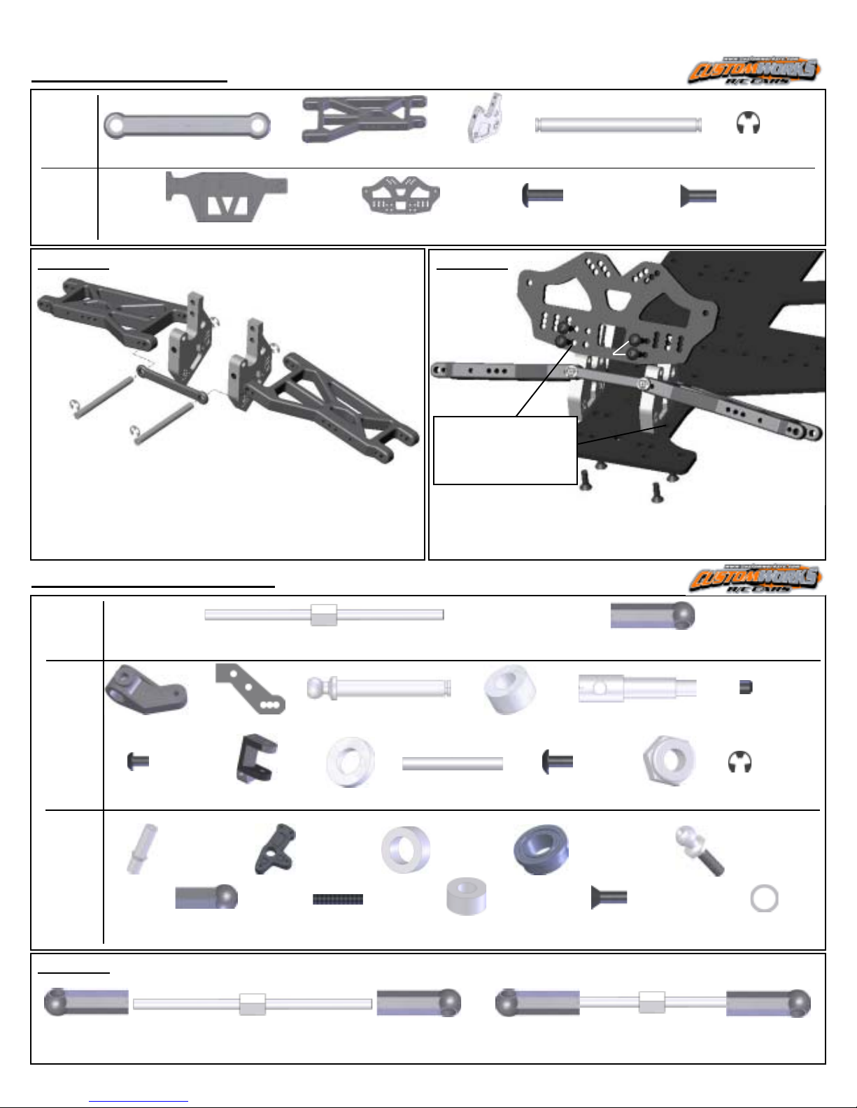
Front SuspensionFront Suspension
Front Suspension
Front SuspensionFront Suspension
-Parts for
Step#1
3332 Qty 1
1.4” Front Susp Brace
1:1
3253 Qty 2
Front Susp Arms L&R
2335 Qty 2
35 deg F Susp Mnt
-Parts for
Step#2
3310 Qty 1
Rocket Chassis
3318 Qty 1
Front Shock Tower
STEP #1 STEP #2
2335
5230
3332
4240
- Insert 4240 Inner Pin thru 3332 Susp Brace, then thru
first leg of 3253 Susp Arm and into 2335 Front Susp
Mount.
- Snap 5230 E-Clips to 4240 Susp Pin.
- Arms should pivot freely on the mounts.
3253
- Suspension mounts
locate in outer
option on chassis &
shock tower.
- Fasten the 3318 tower to the suspension assembly.
- Fasten the suspension assembly to the 3310 Chassis.
5253 Qty 4
4-40 x 3/8 BH Screw
3318
4240 Qty 2
Front Inner Susp Pin
1:1
5253
5263
1:1
5263 Qty 4
4-40 x 3/8 FH Screw
5230 Qty 24
E-Clip
1:1
1:1
3310
Steering ComponentsSteering Components
Steering Components
Steering ComponentsSteering Components
-Parts for
Step#1
-Parts for
3202 Qty 2
Steering Block L&R
1295 Qty 2
Steer Arm Extender
5226 Qty 6
2.375” Ti Turnbuckle
Step#2
1:1
-Parts for
Step#3
5292 Qty 4
M2.5 x 4 BH Screw
3646 Qty 2
Steering Post
3400 Qty 2 (Left Shown)
0 Deg Castor Block
8130 Qty2
Small Ball Cup
3647 Qty 2
Steering Pivot
STEP #1
5235 5226 5235
1:1
7209 Qty 2
Ball Stud King Pin
1255 Qty 6
Spacer
5281 Qty1
4-40 Stud
1:1
4244 Qty 2
Front Outer Susp Pin
7207 Qty 2
Spacer
7209 Qty 4
Spacer
1:1
3234 Qty2
Spacer
5235 Qty 12
Ball Cup
7200 Qty 2
Front Axle
1:1
5252 Qty 6
4-40 x 1/4 BH Screw
1233 Qty 4
Flanged Bearing
5263 Qty 2
4-40 x 3/8 FH Screw
- Make 6 Linkages.
1:1
5217 Qty 2
4-40 Lock Nut
1:1
8122 Qty 5
Ball Stud
5004 Qty 2
6-20 Set Screw
1:1
5230 Qty 24
E-Clip
7047 Qty 6
Spacer
1:1
1:1
- Thread the 5235 Ball Cups onto the ends of the 5226 Turnbuckle.
- NOTE: Turnbuckle has RIGHT and LEFT threads!
1:1 Assembled Camber Link and Steering Linkage.
-Attach to car in Step #3 of this bag.
Page 4
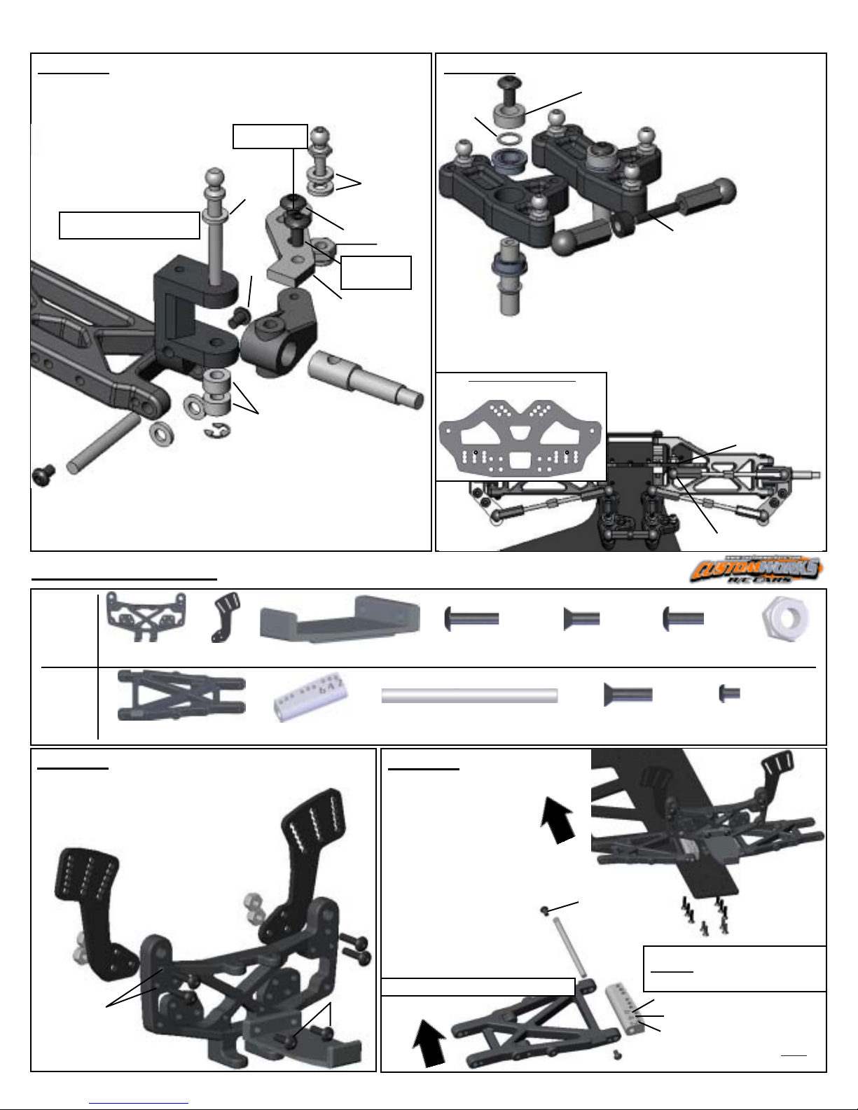
STEP #2
- Insert the 7200 Axle into the 3202 Steering Arm so the
holes are in-line. Attach the 1295 Arm Extender using
5252 Screws.
-Align the Steering Arm into
the 3400 Castor Block and
press the 7209 Ball Stud
Kingpin thru the
assembly as shown.
LF ASSEMBLY SHOWN
SAME ASSEMBLY FOR RF
3400
1255
5292
4244
-Mount the Castor Block to the Susp Arm with a
1255 Spacer on each side of the Castor Block as
it is fitted between the ears of the Susp Arm.
-Insert the 4244 Susp Pin thru the Susp Arm,
Spacer, and Castor Block. Retain by attaching
5292 Screws into the Susp Arm on both sides.
FASTEN 8122 IN
MIDDLE OPTION
1255
7209
5292
7209
Spacer
5230
8122
5252
5252 SCREW
*DRILL HOLE IN
3202 TO USE*
1295
3202
1255
5217
7200
STEP #3
7047
THICK
SHIM
5252
7207
3647
- Press 1233 Flanged
Bearing into each side
of the 3647 Steering
Pivot and thread 8122
Ball Studs as shown in
diagram.
5281
STUD
8130
3647
1233
3234
8130
-Thread 8130 Ball Cups onto 5281
Stud using 3234 Spacer. Tighten
3304
Ball Cups tight to the spacer.
-Tighten each Steering Post to the Chassis using 5263
Screws with Loctite. NOTE: If movement is too tight,
remove the 7047 Thick Shim and use 2 Thin ones.
CAMBER LINK LOCATIONS
- 8122 BALL STUD FACES REAR OF CAR.
-Attach 8122 Ball Stud onto
Shock Tower as shown. Fasten
using 5217 LockNut. Snap
linkages onto ball studs.
5217 LOCKNUT
- SNAP LINKAGES FROM
STEP#1 ONTO BALL STUDS
8122 BALL STUD
Rear SuspensionRear Suspension
Rear Suspension
Rear SuspensionRear Suspension
-Parts for
Step#1
1273 Qty 1
Rear Bulkhead
1285 Qty 2
Tall Shock Ear
-Parts for
Step#2
3254 Qty 2
Long Rear Susp Arm
STEP #1
-Attach the 1285 Long Shock Ears to the
back of the 1273 Bulkhead using 5254
Screws and 5217 Locknuts.
-Attach the 3305 Tail Tank Tray as
shown in the diagram to the front.
1285
5217
5254
1273
5217
3305 Qty 1
Tail Tank Tray
2234 Qty 2
2-4-6 Deg Toe Block
5253
5254 Qty 4
4-40 x 1/2 BH Screw
4247 Qty 2
Rear Inner Susp Pin
STEP #2
- Mount the assembly
from Step 1 using the
screws shown.
-Attach the 3254 Susp
Arm to the 2234 Toe
Block using the 4247
Susp Pin.
-Retain the pin with 5292
Screws on both sides of
5254
Susp Arm.
-Make a RIGHT and LEFT
assembly!
-LEFT Side Assembly Shown.
3254
3305
FRONT
1:1
1:1
5263 Qty 4
4-40 x 3/8 FH Screw
5264 Qty 6
4-40 x 1/2 FH Screw
FRONT
5292
4247
2234
1:11:1
5253 Qty 2
4-40 x 3/8 BH Screw
1:1
5292 Qty 4
M2.5 x 4 BH Screw
5264
“NUMBERS” GO TOWARD REAR OF CAR!!!
NOTE:NOTE:
NOTE: Back side of Toe
NOTE:NOTE:
Block for proper direction!
6 deg Toe-In
4 deg Toe-In
2 deg Toe-In
5292
5264
5263 x4
-CHOOSE THE
THREADED HOLE NEXT
TO THE NUMBER OF
THE DEGREES OF TOE-IN
YOU DESIRE.
-TO START, USE
ON BOTH LEFT & RIGHT.
5217 Qty 4
4-40 Lock Nut
4 DEG4 DEG
4 DEG
4 DEG4 DEG
Page 5
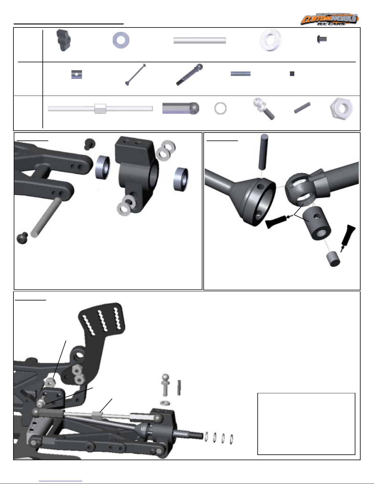
CVD & Drive AssemblyCVD & Drive Assembly
CVD & Drive Assembly
CVD & Drive AssemblyCVD & Drive Assembly
-Parts for
Step#1
-Parts for
Step#2
-Parts for
Step#3
STEP #1
5292
- Press 1226 Ball Bearings into the 3241 Bearing Carrier.
- Attach the Bearing Carrier to the Susp Arm using 4245
Susp Pin with (2) 1255 Spacers on each side of the
Bearing Carrier.
- NOTE: The Suspension Pin will pass thru the UPPER
hole in the Bearing Carrier.
- Retain the Susp Pin using 5292 Screws.
3241 Qty 2
Bearing Carrier
4245
7211 Qty 2
CVD Coupling
5226 Qty 2
2.375” Ti Turnbuckle
5292
1226
1:1
1226 Qty 4
Ball Bearing
7214 Qty 2
Medium Dogbone
1:1
1255
3241
4245 Qty 2
Rear Outer Susp Pin
7216 Qty 2
Rear CVD Axle
5235 Qty 4
Ball Cup
1255
1226
1:1
7211 Qty 2
Rear CVD Pin
1255 Qty 10
Spacer
1:1
7211 Qty 2
CVD Set Screw
5292 Qty 4
M2.5 x 4 BH Screw
1:1
1:1
1:1
7047 Qty 6
Spacer
STEP #2
7214
- Apply grease to the areas shown.
- Apply thread-lock (Loctite) to the set screw.
- Align the holes as shown so that the
7211 CVD Pin can pass thru the Bone,
Axle, and Coupling. Pin should be evenly
spaced in the DogBone.
-Tighten the Set Screw by angling the Bone
and Axle so the set-screw is able to be tightened.
8122 Qty 4
Ball Stud
XXXX Qty 4
Ball Stud
7211
(Pin)
GREASE
7203 Qty 2
Roll Pin
1:1
5205 Qty 2
4-40 Lock Nut
7216
7211
(Coupling)
7211
(Set Screw)
LOCTITE
STEP #3
5205
8122
5226
8122
1255
7203
- Attach the 8122 Ball Stud to the Rear Bulkhead
as shown using a 5205 Lock Nut.
- Slide a 1255 Spcaer onto the Ball Stud and
thread into the Bearing Carrier in the outer most
hole.
- Insert the CVD assembly by sliding the axle thru
the bearings.
- Slide (4) 7047 Shims onto the axle and retain
using the 7203 Roll Pin. Pin should be evenly
spaced in Axle.
- Attach the Camber Link from Bag “B” by snapping the Ball Cups onto the Ball Studs.
TYPICALLY FOR THE ENTIRE AXLE (2) OF
THE THICK AND (2) OF THE THIN #7047
SHIMS WILL SUFFICE FOR PROPER AXLE
SHIMMING.
7047
AXLE IS PROPERALLY SHIMED WHEN
THE LOCKNUT IS TIGHT TO THE WHEEL
AND THERE IS A SLIGHT AMOUNT OF
SIDE-TO-SIDE PLAY OF THE AXLE
VERSUS THE BEARINGS.
Page 6
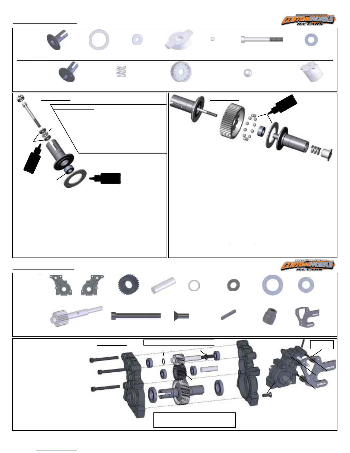
Diff AssemblyDiff Assembly
Diff Assembly
Diff AssemblyDiff Assembly
-Parts for
Step#1
4365 Qty 1
Right Outdrive
4358 Qty 2
Diff Ring
4360 Qty 2
Thrust Washer
-Parts for
Step#2
4361
4364 Qty 1
Left Outdrive
4361
STEP #1 STEP #2
CUSTOM-TIP!!!CUSTOM-TIP!!!
CUSTOM-TIP!!!
CUSTOM-TIP!!!CUSTOM-TIP!!!
-Using 400 Grit Sandpaper in a“Figure 8”
pattern, it is best to sand the surfaces
4359
of both the 4358 Diff Ring and 4360
4362 Qty 1
Diff Spring
Thrust Washers. The textured
4360
surface results in a smoother and
longer lasting diff.
4365
DIFF
LUBE
1229
4358
DIFF
LUBE
- Slide a 4360 Thrust Washer onto the Diff Bolt.
- Apply a thick layer of Black Grease to the Thrust
Washer, press (6) 4359 Thrust Balls into the Black
Grease.
- Slide the other Thrust Washer on the Diff Bolt and
insert it into the 4365 Right Outdrive.
- Press (1) 1229 Bearing into the Outdrive.
- Put (1) 4358 Diff Ring on the Outdrive, apply Diff Lube
as shown.
1:1
4361 Qty 1
Diff Bolt Cover
4356 Qty 1
Diff Gear
4365
4359 Qty 6
Thrust Balls
4356
- Press a small amount of Diff
Grease into each of the small holes
4361 Qty 1
Diff Bolt
4363 Qty 12
Ceramic Diff Balls
4363
1229
1:1
4358
DIFF
LUBE
4364
1:1
1229 Qty 2
5/32 x 5/16 Bearing
4361 Qty 1
Diff T- Nut
4362
in the 4356 Diff Gear.
- Press (1) 1229 Bearing and the (12)
4363 Diff Balls into the Diff Gear.
- Put (1) 4358 Diff Ring onto the 4364 Left Outdrive, apply
Diff Grease as shown.
- Install the 4362 Diff Spring and 4361 T-nut into the
Outdrive.
- Carefully slide the diff assembly together so the Diff Bolt
passes thru the entire assembly and threads into the T-nut.
-Screw the Diff Bolt into the T-nut until you feel the Diff
Spring fully compress. DO NOT OVERTIGHTEN!!!
- Back the Diff Bolt off EXACTLY 1/8 of a turn. Diff motion
should be smooth and the Outdrives will turn in opposite
directions.
4361
TransmissionTransmission
Transmission
TransmissionTransmission
LEFT RIGHT
-Parts for
Trans
- Press the bearings into the
4352 Qty 1
Transmission Halfs
4368 Qty 1
Top Drive Shaft
STEP #1
4352 Trans Case and 4354
Idler Gear as shown.
- Slide 4370 Washers on each
side of the 4368 Top Drive Shaft:
*THICK Shim
*THIN Shim
on short shaft
on short shaft
5285
- Insert components as shown
inside the case halfs.
*Screw for the Diff should be on the
RIGHT side!
*Use a tiny amount of diff lube
on trans gears!
4354 Qty1
Idler Gear
5285 Qty 3
4-40 x 1 1/8 SH Screw
4352
LEFT
1:1
4355 Qty1
Idler Pin
4370 Qty 6
Thin & Thick Spacer
1:1
1:1
- Use diff lube on trans gears!!!
4370 THICK 4370 THIN
1226
1230
5263 Qty 1
4-40 x 3/8 FH Screw
4368
4354
- Diff Screw should be on the
RIGHT side of the Trans!
7047 Qty 8
Thin Shim
4406 Qty 1
Top Shaft Roll Pin
4355
1230
1:1
4352 Qty 3
Motor Plate Spacer
4352
RIGHT
1230 Qty 2
3/8 x 5/8 Bearing
- Press the 4406 Pin
5263
1226 Qty 4
3/16 x 3/8 Bearing
2225 Qty 1
Motor Plate
4406
1:1
4352 SPACER
BEHIND 2225
MOUNT OPTION
2225
into the Drive Shaft.
- Fasten trans using 2225 Motor Plate
using the hole-set option as shown
and the 5263 Screw in the bottom.
Page 7
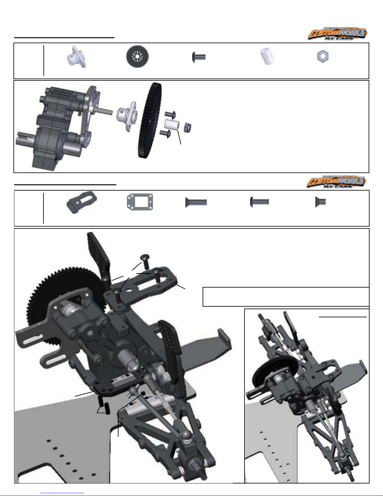
Spur Gear AssemblySpur Gear Assembly
Spur Gear Assembly
Spur Gear AssemblySpur Gear Assembly
-Parts for
Spur
Gear
Assm
2228 Qty 1
Slipper Eliminator
4881 Qty 1
81T 48P Spur Gear
2228
4881
5252 Qty 1
4-40 x 1/4 BH Screw
5252
5245
1:1
2228 Qty 1
Spacer
1:1
5245 Qty 1
5-40 Locknut
- Press the 2228 Slipper Eliminator onto the Top Drive
Shaft so that the Roll Pin keys into the grooves.
- Secure the assembly to the Top Shaft with the 2228
Spacer and the 5245 Locknut. Do NOT overtighten the
nut on the Top Shaft!
Transmission MountTransmission Mount
Transmission Mount
Transmission MountTransmission Mount
-Parts for
Trans
Mount
3308 Qty 1
Transmission Brace
2228
- Mount the 4881 Spur Gear so the flat side faces AWAY
from the transmission. Secure using (2) 5252 Screws.
1202 Qty 1
Trans Spacer
1:1
5264 Qty 2
4-40 x 1/2 FH Screw
1:1
5253 Qty 4
4-40 x 3/8 FH Screw
5262 Qty 1
4-40 x 1/4 FH Screw
1:1
- Mount the 1202 Trans Spacer to the Chassis using the 5262 Screw where shown.
- Secure the Trans to the Chassis using (2) 5264 Screws thru the
1202 Trans Spacer as shown.
- Attach the 3308 Trans Brace to the Trans and Rear
Bulkhead using 5253 Screws.
5253
- Mount the Trans Brace to the Transmission
and Rear Bulkhead using 5253 Screws.
3308
NOTE: Align the dogbone shafts into the outdrives of
Transmission as you mount the trans!
Assembled...
1202
5264
5262
Page 8
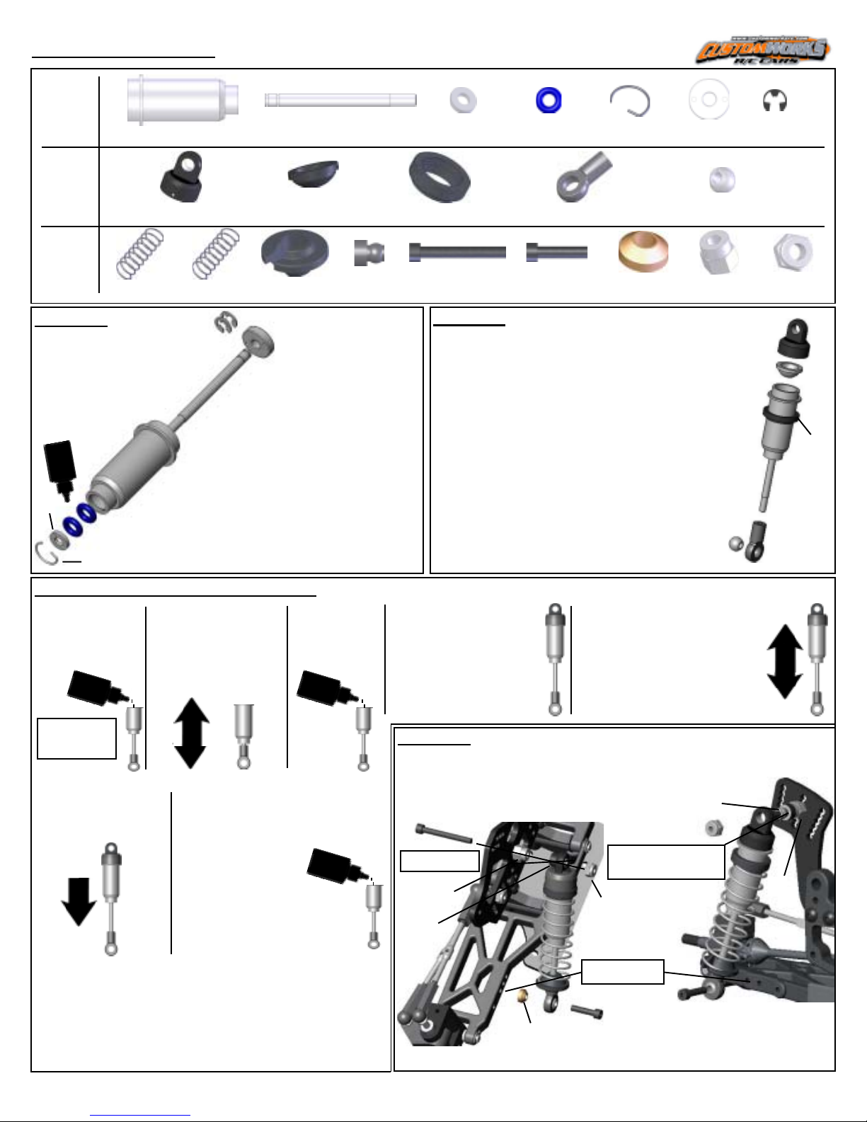
Shock AssemblyShock Assembly
Shock Assembly
Shock AssemblyShock Assembly
Bag JBag J
Bag J
Bag JBag J
-Parts for
Step#1
1424 Qty 4
Long Shock Body
-Parts for
Step#2
REAR FRONT
-Parts for
Step#3
1804 Qty2
(WHITE) Spring
STEP #1
NOTE: Put a few
drops of oil on the
O-Rings!
1250
1435
1424
TIP: To press clip in easiest, compress the
clip so the diameter is a little smaller.Insert
open end of clip first, working counterclockwise to the bent end as shown.
OIL
1434
1428 Qty4
Long Shock Shaft
1438 Qty4
1 Piece Cap
1807 Qty2
(GREEN) Spring
5230
1428
1437 Qty 4
Bladder
1407 Qty4
Spring Bucket
1436
- Attach 1436 Shock Piston to
Shock Shaft using 5230 E-Clips
to secure.
- Press 1250 O-rings into the
Shock
Body followed by 1434 Shaft
Guide. Retain using 1435 Clip.
1408 Qty4
Mount Ball
M
1434 Qty4
Shaft Guide
1433 Qty4
Spring Collar
5277 Qty 4
4-40 x 7/8 SH Screw
1250 Qty 8
O- Ring
5228 Qty4
Short Ball End
5274 Qty 2
4-40 x 1/2 SH Screw
1435 Qty 8
Reatining Clip
5233 Qty 2
Coned Washer
1436 Qty4
Piston
5228 Qty2
Pivot Ball
2214 Qty 4
.250” Hex Spacer
STEP #2
- Snap Pivot Ball into the 5228 Ball End. Thread the
Ball End onto the Med Shock until the Ball End is
flush with the end of threads on the shaft. Do the
same with the 5235 Ball Cup to the Short Shock.
- Press the 1437 Firm Bladder (BLACK) into the
Threaded Shock Cap so the dome of the
bladder points away from the Eyelet Cap.
- Thread 1433 Spring Collar onto the
Shock Body.
-NOTE: See shock filling tips for more
instructions.
1:1
5230 Qty 10
E-Clip
5217 Qty 4
4-40 Lock Nut
1438
1437
1433
5228
SHOCK FILLING INSTRUCTIONS:
1) Holding the
shock upright, fill
with oil until the
top of the body.
OIL
40 wt
suggested
starting point.
6) Then the shaft
should push itself
out to its full length
slowly.
8) If the shockrebounds too fast , or you cannot push
the shaft in until the eyelet hits the body, there is
too much oil. Loosen the cap about 2 full turns and
pump out a small amount of oil by pushing the shaft
in. Retighten the cap and try steps 5-6 again.
2) Slowly move the
shaft up and down
several times to allow
air bubbles to escape
to the top.
3) Refill with
oil to the top
of the shock
body.
OIL
7) If the shock does not push
out this far there is not enough
oil in it. Add just a little oil and
try steps 5-6 again.
OIL
4) Thread the Eyelet
Cap assembly onto
the Shock Body until it
is hand tight. Oil
should seep out of the
bleed hole in the
5) Move the shock shaft in
and out a few times and
then push it all the way in. It
should be easy to push the
shaft in until the eyelet hits
the body.
Threaded Cap.
STEP #3
- Slide 1804 White Springs on the Rear Shocks /1807 Green
Spring on the Front Shocks. Secure using the 1407 Spring Bucket
-
Insert 5277 Screw thru hole shown in tower
and tighten 2214 onto the screw.
FRONT
5277
- OUTER OPTION,
MIDDLE HOLE
2214
1408
SHOCK
EYELET
5233
CONED
WASHER
- 5277 SCREW LOCATES IN
4TH HOLE FROM BOTTOM
ON BOTH REAR TOWERS.
5217
- 5274 MOUNTS IN
THIS OPTION.
- Place shock on screw, retain with
1408 Shock Eyelet and 5217 Nut.
- Fasten the bottom eyelet of the
5274
shock to the arm using 5274 Screw.
5217
5274
REAR
1408
2214
.
Page 9
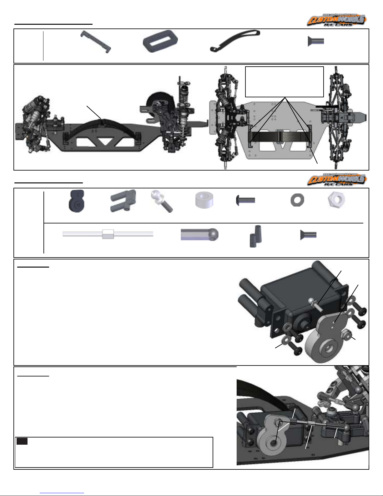
Battery MountsBattery Mounts
Battery Mounts
Battery MountsBattery Mounts
Bag KBag K
Bag K
Bag KBag K
-Parts for
Battery
Mounts
3266 Qty 2
Li-Po Locator
3009 Qty 1
Strap Buckle
- Insert the 3266 Lipo Locator thru the small loop on each
3009 Battery Strap. Mount to chassis using 5263 Screws.
3009
STRAP BUCKLE
- Insert each tab of the 3009 Battery Strap thru the Strap Buckle.
Simply pull the strap tabs tight to secure your battery into the car.
Servo MountsServo Mounts
Servo Mounts
Servo MountsServo Mounts
-Parts for
Steps
5242 Qty 1
Large Servo Saver
5240 Qty2
Servo Mount
8122 Qty 2
Ball Stud
3234 Qty2
Spacer
#1
3009 Qty 2
Battery Strap
5253 Qty 4
4-40 x 3/8 BH Screw
5263 Qty 8
4-40 x 3/8 FH Screw
- LOCATE THE SCREWS TO
FASTEN 3266 TO CHASSIS
IN THE 4TH AND 6TH HOLES
FROM THE LEFT EDGE OF THE
CHASSIS.
3266
1:1
5212 Qty 4
Washer
1:1
5217 Qty 8
4-40 Lock Nut
1:1
5225 Qty1
2” Ti Turnbuckle
5235 Qty 2
Ball Cup
STEP #1
- Attach 5240 Servo Mounts to your steering servo in the position shown
using 5253 Screws and 5212 Washers.
- Thread 8122 Ball Stud into the upper-most center hole in the 5242 Servo
Saver and 5217 Locknut as shown.
NOTE: Using inner hole on servo saver will decrease steering speed if desired.
5240
- Determine which of the Spline Inserts are correct for your servo by pressing
SERVO
MOUNT
it over the drive on the servo. Align the servo so it has equal throw in both
directions, you may need to do this with the radio system powered.
- Press the Servo Saver onto the Spline Outdrive and attach the Servo Saver
using the screw that came with your servo.
STEP #2
- Mount the servo to the chassis using 5263 Screws in the 3rd row of
holes from the right edge of the chassis.
- Thread the 5235 Ball Cups onto the 5225 Turnbuckle. Snap the Ball
Cups onto the Ball Studs on the Servo Saver and the Bell Crank.
- Adjust Draglink length so that the Servo Saver is 90 Degree to the Drag
Link AND the Bell Cranks are parallel to the Chassis at the same time.
- Attach 3209 Antenna Mount into a vacant hole in the chassis.
TIP
Remove extra slop in the Ball Cups and Ball Studs by placing
the plastic bag these parts came in between the Cup and Ball Stud
as you snap them together. This will create a perfect shim and
make the steering unit very tight. Linkages should still pivot freely.
3209 Qty1
Antenna Mount
5212
WASHER
5263 Qty 5
4-40 x 3/8 FH Screw
5253
SCREW
5235
90
DEGREE
5225
- Steering movement should be bind free
except for the restriction of the servo.
5235
8122
5242
SERVO SAVER
UPPER
HOLE
5217
Page 10
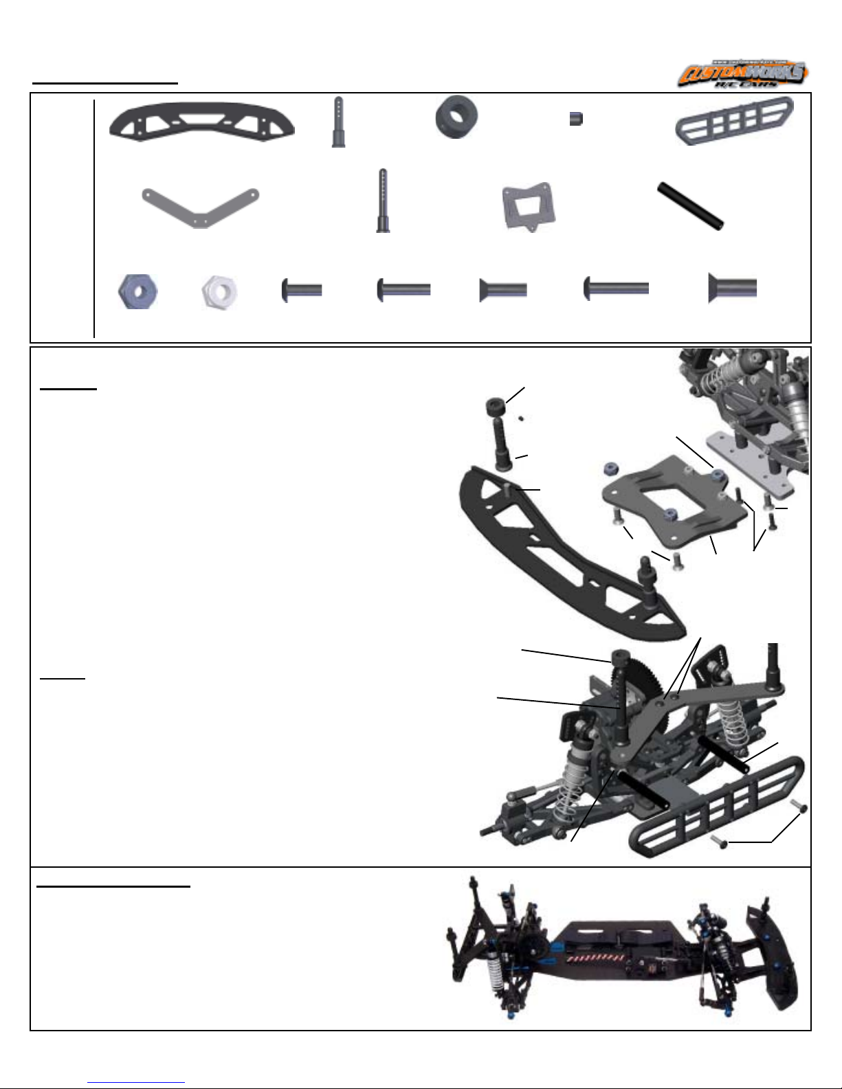
Body MountsBody Mounts
Body Mounts
Body MountsBody Mounts
3015 Qty1
INT Front Bumper
3229 Qty2
Short Body Post
-Parts for
Body
Mounts
1004 Qty 1
Rear Body Mount
3228 Qty2
Long Body Post
1:1
5207 Qty 3
8-32 Lock Nut
5217 Qty 4
4-40 Lock Nut
5253 Qty 2
4-40 x 3/8 BH Screw
5254 Qty 4
4-40 x 1/2 BH Screw
FRONT
- Slide the Post Collar onto the 3229 Short Body Post, use the
Set Screw to retain the Collar.
- Mount the (2) 3229 Short Body Posts to the rearward set of
holes on the 3015 Bumper using 5283 Screw.
- Attach and center the 3015 Bumper to the 1275 Front Clip
using 5283 Screws and 5207 Nuts. The bumper is slotted to
allow you to adjust the body position easily.
- Mount the 1275 Front Clip to the Chassis using (1) 5283 Screw
and 5207 Nut along with (2) 5264 Screws and 5217 Nuts.
3229 Qty4
Post Collar
1275 Qty1
INT Front Clip
1:1 1:1
5264 Qty 2
4-40 x 1/2 FH Screw
3229
COLLAR
SET SCREW
3229
POST
3015
3229 Qty 4
Set Screw
1:1
5283
5255 Qty 2
4-40 x 5/8 BH Screw
5207
5283
3659 Qty 2
Rear Bumper Post
5207
3658 Qty 1
Rear Bumper
1:1
5283 Qty 7
8-32 x 1/2 FH Screw
1275
5264
5283
REAR
- Mount the (2) 3228 Long Body Posts to the 1004 Rear Body
Mount.
- Attach and center the 1004 to the Trans Brace using 5253
Screws and 5217 Lock Nuts.
- Fasten the 3659 Bumper Post to the rear bulkhead in the
vacant screw hole in the shock ears using 5255 Screws. Attach
the 3658 Rear Bumper to the posts using 5254 Screws
BODY MOUNTING:
- Different bodies provide different handling characteristics,
we suggest using the CW #9016 Paducah for this kit.
- Correctly mounting of the body also provides a great
amount of stability too, this being said set the collars so
that the body clips will retain the body in the 2nd hole from
the top on the REAR body posts and the 3rd hole from the
top on the FRONT body posts.
3228
POST
3229
COLLAR
5253
5255 5254
3658
3659
Page 11
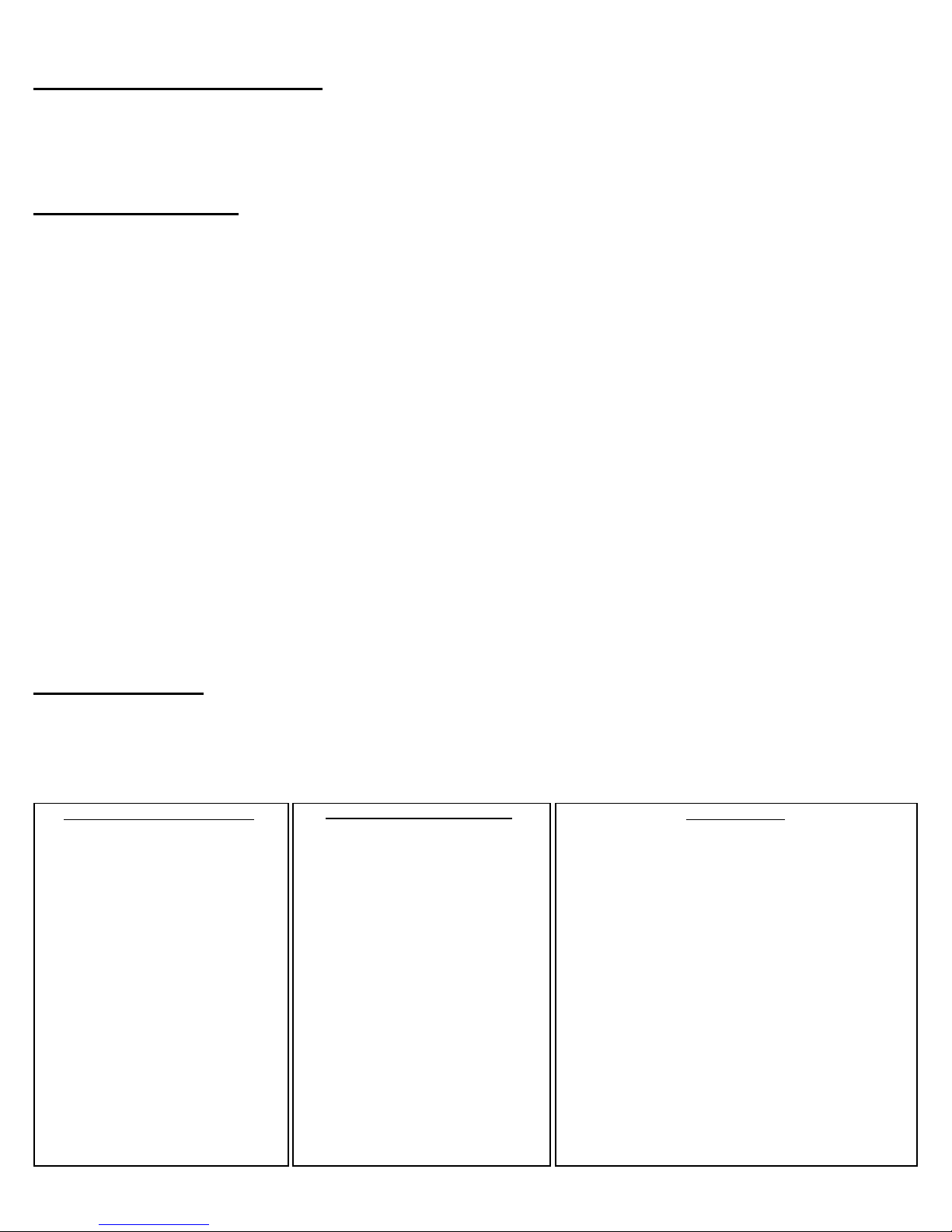
CONGRATULATIONS!!!CONGRATULATIONS!!!
CONGRATULATIONS!!!
CONGRATULATIONS!!!CONGRATULATIONS!!!
You have now completed the assembly process of your
new Custom Works Pro Comp Rocket. In the next section of this manual you will find some
basic setup hints and advice. It is important to remember that all tracks and racing surfaces
are different. Therefore the suggestions we give you are general in nature and should by no
means be treated as the only options.
MAINTENANCE:MAINTENANCE:
MAINTENANCE:
MAINTENANCE:MAINTENANCE:
Occasionally dirt will get into the moving and pivoting locations in your car. It is best to
periodically clean your car to keep all the suspension components moving freely. Read the tips
below to keep your car running at its best!
- Begin by removing the majority of the dirt using a small brush, toothbrush, or compressed air.
- Compressed air is ok to use, be mindful to not FORCE the dirt into the radio gear, transmission,
bearings, or air filter. Typically these items only have dirt on them, hitting the dirt with the
compressed air puts dirt
ININ
IN
these parts!
ININ
- Tires, either foam or rubber are best cleaned using water or cleaners like Simple Green (TM). Simple
Green also does a great job cleaning car parts as well. Lightly spraying car parts (NOT radio
components, transmission, air filter, or bearings) with Simple Green and blowing off with compressed
air or wiping the parts using the paint brush is a great way to clean in a hurry.
- Another R/C friendly cleaner is WD-40 (TM). After the car is clean, very lightly spray the car
components and bearings (NOT radio components, transmission, or air filter). Use your brush or
compressed air to remove the extra WD-40. This will lube your bearings and leave a protective
coating on the parts making it easier to remove dirt later.
- Differential Maintenance is needed when the action of the diff feels “notchy”. Usually cleaning the
diff parts, re-sand the thrust and diff plates with 400 paper, and lube appropriately will be all that is
needed to bring back to new. Ignoring your differential will lead to handling woes and increase
transmission temps, which will cause part failure.
TUNING TIPS:TUNING TIPS:
TUNING TIPS: These are some general guidelines for optimizing handling performance.
TUNING TIPS:TUNING TIPS:
None of these “tips” are EVER set in stone. On any given day this manual or any chassis
engineering book or guru can be proved wrong by the stop watch. A good way to approach
chassis set-up is to try one change, practice it, think how the car felt different from before,
and compare lap times from the stop watch…..this will never fail.
Car Is Loose (oversteers):Car Is Loose (oversteers):
Car Is Loose (oversteers):
Car Pushes (understeers):Car Pushes (understeers):
Car Pushes (understeers):
Car Pushes (understeers):Car Pushes (understeers):
- Decrease Spoiler Angle
- Decrease Spoiler Length.
- Heavier Rear Spring
- Softer Front Spring
- Use Rear Sway Bar
- Try Softer Front Compound Tire
- Try Harder Rear Compound Tire
- Lower Front Ride Height
- Raise Rear Ride Height
- Thread Shock Collar UP on
Right Front
- Thread Shock Collar DOWN on
Right Rear
- Decrease Rear Toe
- Decrease Castor
- Add Rear Toe Stagger or
Increase the difference
Car Is Loose (oversteers):Car Is Loose (oversteers):
- Increase Spoiler Angle
- Add Spoiler Length.
- Softer Rear Spring
- Heavier Front Spring
- Use Front Sway Bar
- Try Harder Front Compound Tire
- Try Softer Rear Compound Tire
- Raise Front Ride Height
- Lower Rear Ride Height
- Thread Shock Collar
DOWN on Right Front
- Thread Shock Collar UP on
Right Rear
- Increase Rear Toe
- Increase Castor
- Decrease Rear Toe Stagger or
Decrease the difference
Car Is Erratic:Car Is Erratic:
Car Is Erratic:
Car Is Erratic:Car Is Erratic:
- Bent Suspension Pins: Remove shocks to check
free movement.
- Bound Ball Joint: Should spin free on balls
while mounted to the car.
- Bent or Loose Camber Links
- Wore out Bearings or Completely Seized
Bearings
- Chunked Tire: Check to see if Foam or Rubber
Tire is still glued to wheel.
- Loose Screws: Especially Chassis Screws, add
Blue Loctite to prevent.
- Shocks: Either Bound-up or Out of Oil. Must
swivel freely on mounts.
- Foreign Objects: Unlucky Dirt/Stones
preventing Suspension or Steering Movement.
- Blown Differential
- Radio Problem: Bad Servo, Weak Servo Saver
Spring, Transmitter Pot blown.
Page 12

SET-UP GUIDELINES:SET-UP GUIDELINES:
SET-UP GUIDELINES:
SET-UP GUIDELINES:SET-UP GUIDELINES:
When looking for the “perfect set-up” it is important to remember 2 things...
1) Keeping things simple is best.
2) As you are making your set-up change, the track is changing too! Ask a local racer what the
track usually does from begining to end, especially day to night.
- Start your car’s ride height with it equal at all four corners to start. Use the shock collars to adjust
ride height by measuring the distance under the chassis when the car is sitting on a FLAT & LEVEL
surface.
- Shock collars can only jack weight and adjust the car’s handling when the car makes ALL 4
shocks squat when the car is set down. Use the RF shock collar to adjust how the car ENTERS the
corner. Use the RR shock collar to adjust how the car exits the corner ON-POWER. Use the LF shock
collar to make the car turn in less, and off the corner more.
- It is best to have a little bit of brake drag when you let off the gas, this will allow for a more
controlable car in ALL conditions. Increasing how much the brake drags will make your car turn
into the corner harder but can make the car also much more loose to drive into the corner.
SET-UP GLOSSARY:SET-UP GLOSSARY:
SET-UP GLOSSARY:
SET-UP GLOSSARY:SET-UP GLOSSARY:
Caster:Caster:
Caster: Angle of the kingpin in relation to a vertical plane as viewed from the side of the car.
Caster:Caster:
Increasing the angle will make the car more stable out of the turn and down the straights and
increase steering entering a turn. Decreasing the angle will make the car feel more “touchy” at high
speeds and help steering while exiting the turn.
Camber Gain:Camber Gain:
Camber Gain: Angle of the Camber Link relative to the Suspension Arm. Lowering the
Camber Gain:Camber Gain:
camber link on the shock tower OR raising the camber link on the castor block will INCREASE
the camber angle of the tire when the suspension is compressed. Raising the camber link on
the shock tower OR lowering the camber link on the castor block will DECREASE the camber
angle of the tire when the suspension is compressed. There is not a “correct” set-up and once
again too much of anything is generally bad. This will help change the “feel” of the car thru
the turns.
Camber Link Length:Camber Link Length:
Camber Link Length: Comparing this to the length of the Suspension Arm from each pivot
Camber Link Length:Camber Link Length:
point and keeping the Camber the same, making the link
that corner of the car while making it
Once the camber link is equal to or greater than the Suspension Arm pivots, the gain of
traction ends. Also a shorter camber link will increase camber gain and a longer decrease
camber gain.
Shock Angle:Shock Angle:
Shock Angle: Leaning the shock toward the car is effectively like changing to a
Shock Angle:Shock Angle:
Standing the shock closer to vertical is effectively like changing to a
the car is working well and when one spring change is TOO much for your set-up.
Ride Height:Ride Height:
Ride Height: Check by pushing the chassis down once or twice to simulate bumps on the
Ride Height:Ride Height:
track. Having the front end
especially out of the turn. Having the front end
increase front traction especially entering the turn. Generally its safe to start the car with the
ride heights even.
higher
longer
than the rear will make the car increase rear traction
will increase traction for that corner of the car.
lower
shorter
than the front will make the car
will decrease traction for
softer
stiffer
spring. Try when
spring.
Rear Toe-In:Rear Toe-In:
Rear Toe-In: Front edge of car tires point
Rear Toe-In:Rear Toe-In:
Increasing the angle toward the car will increase rear traction while decreasing front traction.
Decreasing the angle will do the opposite.
toward
the chassis as viewed from above the car.
Page 13
Rear Toe Stagger:Rear Toe Stagger:
Rear Toe Stagger:
Rear Toe Stagger:Rear Toe Stagger:
Difference in the amount of Rear Toe-In among the rear tires. Typically used
only on high bite tracks with MORE toe-in on the Left Rear tire than the Right so the rear of
the car helps turn the car LEFT under acceleration.
Wheelbase (Front End):Wheelbase (Front End):
Wheelbase (Front End): Wheelbase is the distance between the front and rear axles.
Wheelbase (Front End):Wheelbase (Front End):
Running the entire front end assembly in the forward position makes the wheelbase longer
and therefore more stable on long/fast tracks with flowing turns. Running the entire front
end assembly in the rear position make the wheelbase shorter and therefore more suitable for
short-tracks where you are constantly turning.
Wheelbase (Rear End):Wheelbase (Rear End):
Wheelbase (Rear End): This adjustment uses the plastic spacers on the kingpin the rear
Wheelbase (Rear End):Wheelbase (Rear End):
bearing carrier rides on. With the spacers in front of the carrier it will lengthen the wheelbase
but will increase steering. If the spacers are behind the carrier it will shorten the wheelbase
but increase rear traction. This is completely backwards from how it works for the Front End
only because in the rear of the car you have the weight of the motor and the torque it creates.
Shortening the wheelbase here makes more of the car hang over the rear tires and promotes
more weight transfer.
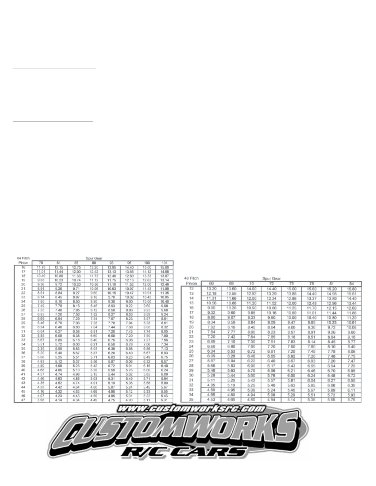
Final Drive Chart:Final Drive Chart:
Final Drive Chart: The chart provided below gives you the final drive of the motor to spin the
Final Drive Chart:Final Drive Chart:
axle 1 revolution. This chart is NOT just the pinion and spur, but has the transmission ratio
included as well.
- To determine the final drive in your car:
1) Divide the Spur Gear by the Pinion Gear, which
equals a “Ratio”.
2) Multiply the “Ratio” by the “Transmission Ratio”
which will equal your “Final Drive”.
***Transmission Ratio = 2.4 for this car.***
- Gearing choice can vary greatly depending
on track size, surface type, amount of traction,
you motor and driving style. For starters
consult your local hobby dealer or fellow
racer at your local track for the ideal gear
choice for your application.
 Loading...