

Page 1
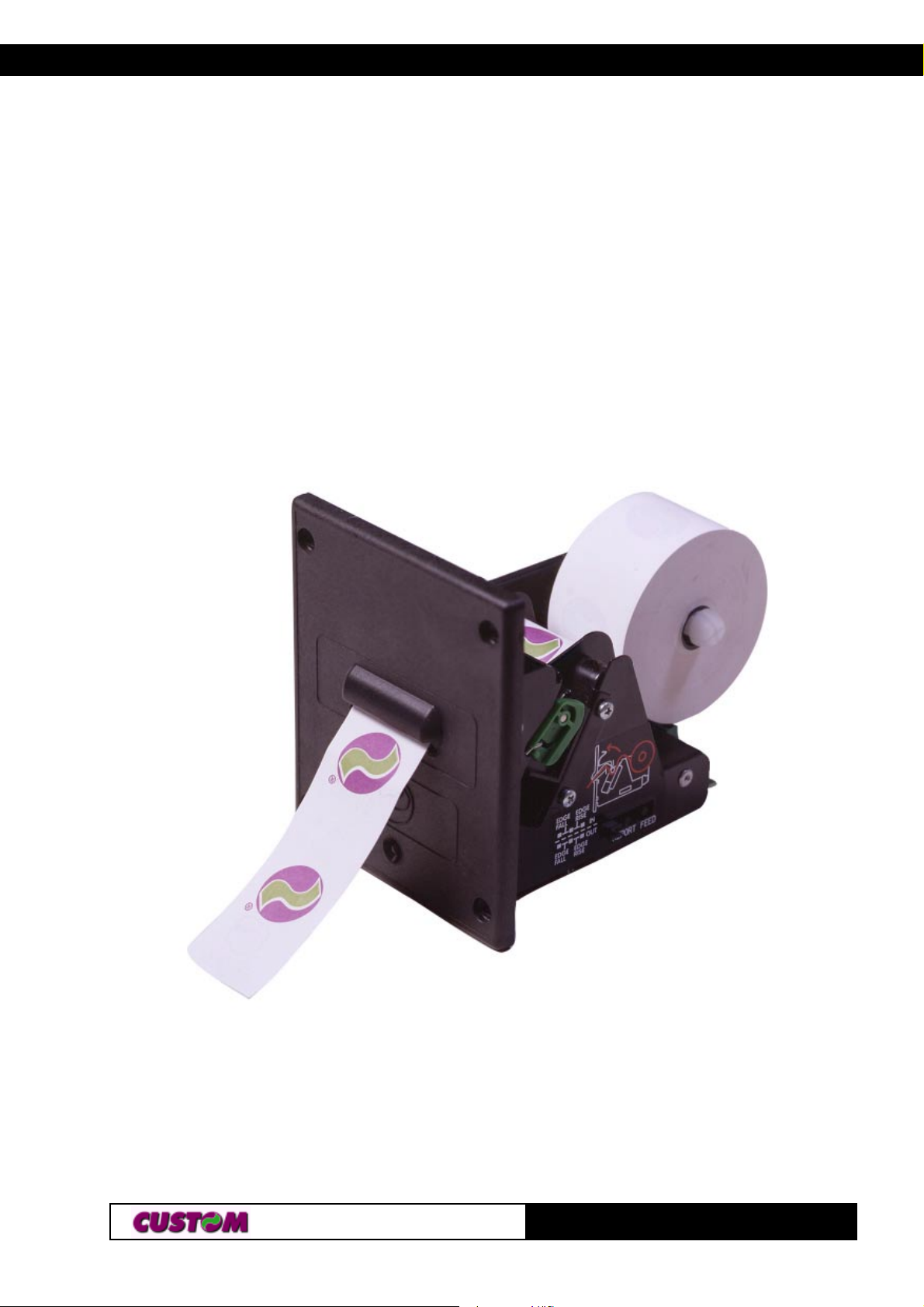
TG35/58-T
Printer version
User Manual
www .custom.it
TG35/58-T
Page 2
All rights reserved. Total or even partial reproduction of this manual in any
form, whether on paper or electronically, is strictly forbidden. While CUSTOM
ENGINEERING SPA guarantees that the information contained in this manual
has been carefully checked and verified, CUSTOM ENGINEERING SPA and
other resources utilized in its creation assume no responsibility for situations
arising from its use.
Feedback regarding any errors in the manual’s content or suggestions on
how it could be improved would be greatly appreciated. Since its products
are subject to continuous checking and improvement, CUSTOM
ENGINEERING SPA reserves the right to modify the information contained
in this manual without prior notice.
COD. DOME - TG35-58-T VERS. 1.33
Copyright 2001 CUSTOM ENGINEERING SPA – Italy
CUSTOM ENGINEERING SPA
Str. Berettine 2 - 43010 Fontevivo (PARMA) - Italy
Phone : +39 0521-680111 - Fax : +39 0521-610701
http: www .custom.it http: www .smice.com
To contact our Technical Support :
Phone. : +39 0521-680163 - Fax : +39 0521-680146
Email : [email protected]
TG35/58-T
Page 3
PRINTER COMPONENTS
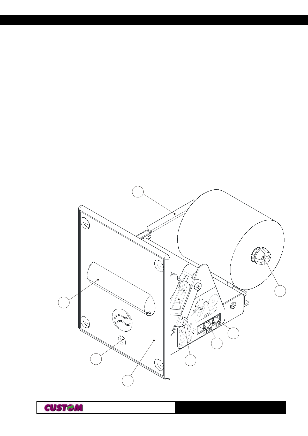
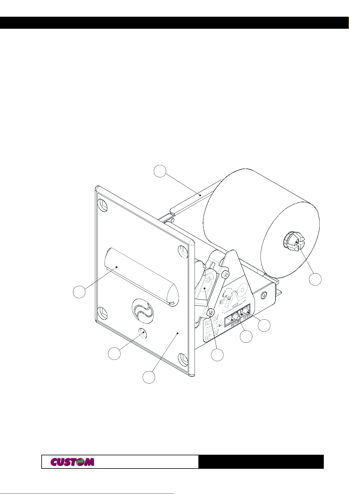
A. TG35/58-T - exterior view
1- Printing mechanism
2- Report “Key”
3- Feed “Key”
4- Paper roll support
5- Case
6- Front panel
7- Led
8- Paper output
8
5
4
3
7
2
1
6
TG35/58-T
Page 4
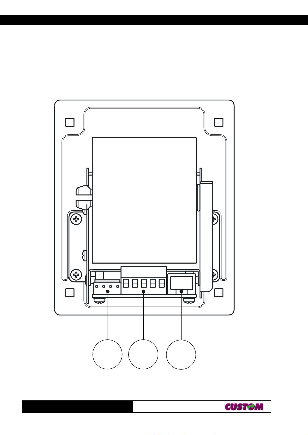
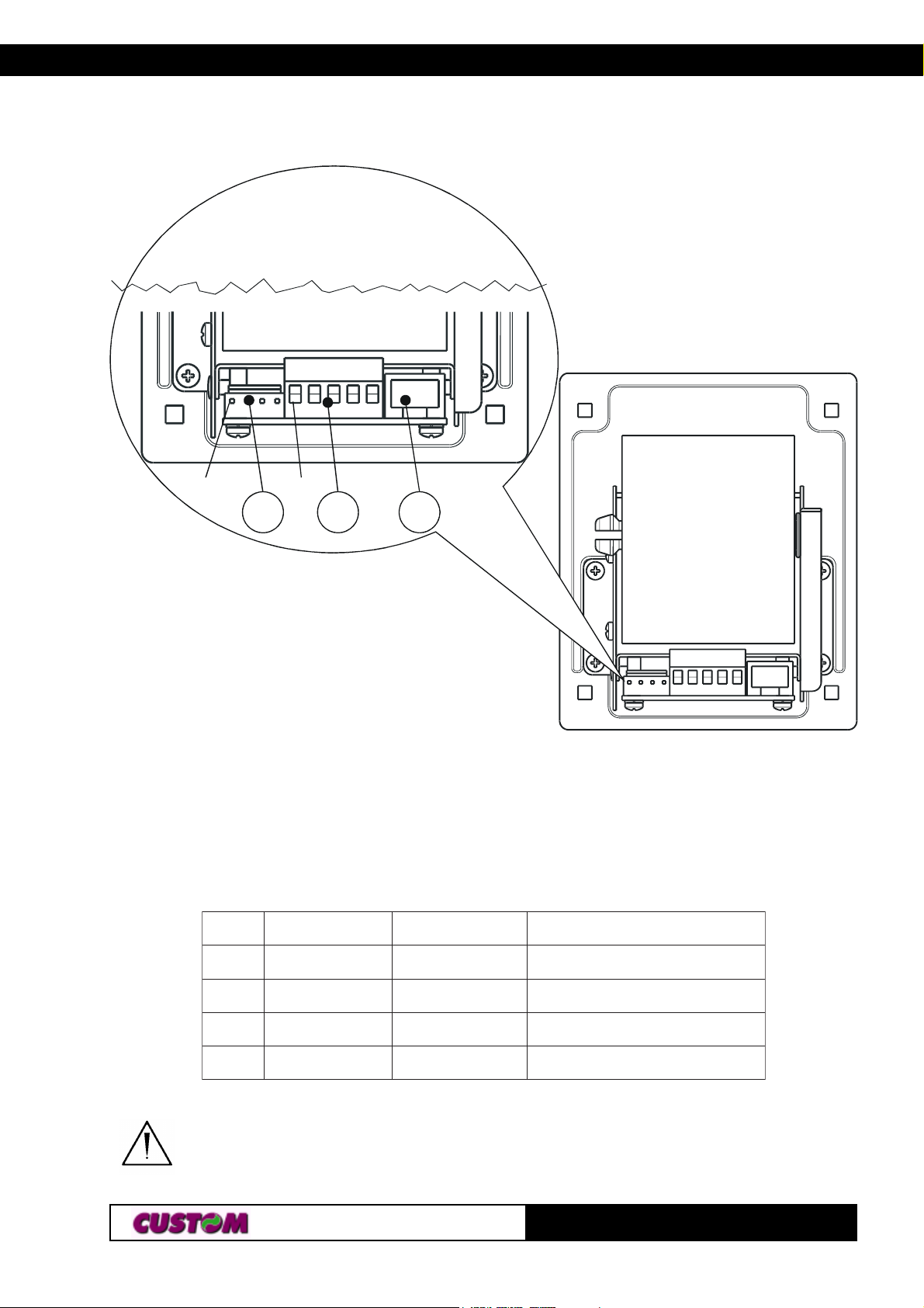
B. TG35/58-T - rear view
1- Power supply connector
2- Power supply connector and additional signals
3- TTL serial interface connector
TG35/58-T
1 2
3
Page 5

TABLE OF CONTENTS
INTRODUCTION
MANUAL ORGANIZATION ............................................................................1
SYMBOLS USED IN THE MANUAL............................................................... 1
GENERAL SAFETY INFORMATION ............................................................. 1
UNPACKING THE PRINTER ......................................................................... 2
MAIN CHARACTERISTICS ........................................................................... 2
PRINTER DESCRIPTION ............................................................................. 3
1. INSTALLATION AND OPERATION
1.1 CONNECTIONS ................................................................................... 1-1
1.1.1 Power supply and Input/Output ...................................................... 1-1
1.2 SETUP .................................................................................................. 1-2
1.2.1 Configuration of REPORT and FEED keys ................................... 1-3
1.3 AUTOTEST .......................................................................................... 1-3
1.4 CAUTIONS ........................................................................................... 1-3
1.5 MAINTENANCE.................................................................................... 1-4
1.5.1 Using the control discs................................................................... 1-4
1.5.2 Changing the paper roll .................................................................. 1-4
2. INTERFACES
2.1 TTL SERIAL ......................................................................................... 2-1
3. PRINTER FUNCTIONS
3.1 COMMAND DESCRIPTIONS .............................................................. 3-1
3.1.1 ESC/POS Emulation ..................................................................... 3-1
4. TECHNICAL DATA
4.1 TECHNICAL DATA............................................................................... 4-1
4.2 DIMENSIONS ....................................................................................... 4-2
i
TG35/58-T
Page 6

TABLE OF CONTENTS
APPENDIX A - ACCESSORIES AND SPARE PARTS
A.1 ACCESSORIES................................................................................... A-1
A.1.1 Power supply ................................................................................. A-1
A.1.2 RS232 cable adaptation ................................................................ A-2
A.2 SPARE PARTS .................................................................................... A-5
TG35/58-T
ii
Page 7
INTRODUCTION
MANUAL ORGANIZATION
In addition to the Introduction which contains information regarding the
symbols used in the manual, general safety information, instructions for
unpacking the printer and a brief description and main characteristics of the
machine, this manual is divided into the following chapters:
Chapter 1: Contains the information required for correct printer installation
and use
Chapter 2: Contains interface data
Chapter 3: Contains a description of printer controls
Chapter 4: Contains printer technical data
Chapter 5: Contains the character sets (fonts) used by the printer
SYMBOLS USED IN THE MANUAL
NOTE
Gives important information or suggestions for printer use.
WARNING
Information indicated by this symbol must be followed carefully to
avoid damaging the printer.
DANGER
Information indicated by this symbol must be followed carefully to
avoid damage or operator injury.
GENERAL SAFETY INFORMATION
• Read and retain the instructions which follow.
• Before cleaning the printer, be sure to pull out the electrical cable.
• Use a damp cloth to clean the printer. Do not use liquid or spray products.
• Do not operate the printer near water.
• When positioning the printer, make sure its cables will not be damaged.
• Use the type of electrical power supply indicated on the printer label. If
uncertain, contact your dealer.
• Do not block the ventilation openings.
1
TG35/58-T
Page 8

INTRODUCTION
• Do not insert objects inside the printer as this could cause short-circuiting
or damage components that could jeopardize printer functioning.
• Do not spill liquids onto the machine.
• Do not carry out repairs on the machine yourself, except for the normal
maintenance operations given in the user manual.
• Unplug the printer from the electrical mains and call a specialized
repairman if any of the following conditions should arise:
A. the power supply connector is damaged
B. liquid has spilled into the printer
C. the printer has been exposed to rain or water
D. the printer is not functioning normally despite the fact that all
instructions given in the user manual have been followed
E. the printer has been dropped and the cover is damaged
F. printer performance is noticeably reduced
G. the printer is not working
UNPACKING THE PRINTER
Remove the printer from the carton, taking care not to damage the packing
materials which should be retained for future shipping/moving.
Make sure all components listed below are present and not damaged. If any
part is missing and/or damaged, contact customer service.
1. Manual (or CD-rom)
2. Printer
3. Discs control of paper roll
MAIN CHARACTERISTICS
The TG35/58-T printer is the ideal solution for :
• Gaming machines
• Vending machines
• Self-service machines
• Paper tear-off and anti-paper jam system.
• Optional RS232 cable adaptation.
TG35/58-T
2
Page 9
INTRODUCTION
PRINTER DESCRIPTION
It is equipped with a 200 dpi thermal print mechanism that uses paper with a
width of 35/58 mm; it has a TTL serial interface (optional RS232 cable) and
is also equipped with a calendar clock (Real Time Clock).
The TG35/58-T printer consists of a case (5) onto which the following
components are fitted: thermal print mechanism (1), paper roll pin (4) front
panel (6) in PPO for installation on Gaming/Vending Machines.
5
8
3
2
7
1
(Fig. 1)
6
• When the “REPORT” key (2) is pressed, it prints the printer operational
report.
• When the “FEED” key (3) is pressed, the paper can be fed forward
manually.
4
3
TG35/58-T
Page 10

INTRODUCTION
• The red Status LED (7) displays a printer hardware error status and the
winnings. The check is carried out“on line”, i.e. in the event of a
malfunctioning, the LED will starts flashing as follows:
(Tab.1)
DELSUTATSDELSUTATS
DELSUTATSDELSUTATSNOITPIRCSEDNOITPIRCSED
DELSUTATS
NOITPIRCSEDNOITPIRCSED
NOITPIRCSED
FFOsyawlAFFOretnirP
NOsyawlAstluafon–NOretnirP
)doirepgnolarofno(gnihsalfwolSdesiarrevocgnitliT
)doireptrohsarofno(gnihsalfwolSegasseMtuOrepaP
TG35/58-T
4
Page 11
1. INSTALLATION AND OPERATION
1.1 CONNECTIONS
(Fig.1.1)
Pin 1
Pin 1
J3 J8 J9
1.1.1 Power supply and Input/Output
As regards the power supply, the printer TG35/58-T is equipped with a Ticket Outlet-compatible 4-pin male connector (J3). The signals on the pins of
the feed connector are as follows:
NIPNIP
NIPNIPLANGISLANGIS
NIP
LANGISLANGIS>TUO/NI<>TUO/NI<
LANGIS
>TUO/NI<>TUO/NI<NOITPIRCSEDNOITPIRCSED
>TUO/NI<
NOITPIRCSEDNOITPIRCSED
NOITPIRCSED
11111
22222
33333
44444
.C.N- detcennoctoN
V21+REWOPREWOP
DNGREWOPREWOP
.C.N- detcennoctoN
WARNING:
Be sure to observe the correct polarity for the power supply.
11-
TG35/58-T
(Tab.1.1)
Page 12
1. INSTALLATION AND OPERATION
As regards the power supply and additional signals, the TG35/58-T printer is
equipped with a 5-pin screw terminal connector (J8). The signals on the
connector pins are as follows:
NIPNIP
NIPNIPLANGISLANGIS
NIP
LANGISLANGIS>TUO/NI<>TUO/NI<
LANGIS
>TUO/NI<>TUO/NI<NOITPIRCSEDNOITPIRCSED
>TUO/NI<
(Tab.1.2)
NOITPIRCSEDNOITPIRCSED
NOITPIRCSED
11111
22222
33333
44444
55555
V21+REWOPREWOP
DNGREWOPREWOP
ATUPNIYRAILIXUA).C.O(NIROTCELLOCNEPO
BTUPNIYRAILIXUA).C.O(NIROTCELLOCNEPO
TUPTUOYRAILIXUA).C.O(TUOROTCELLOCNEPO
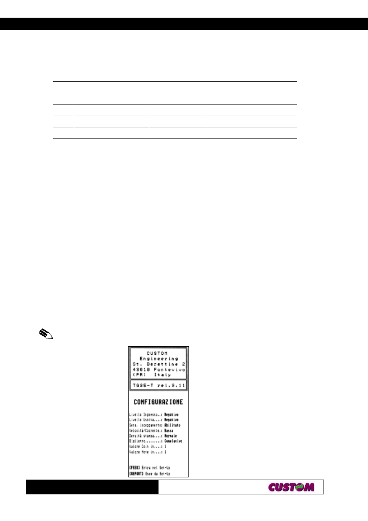
1.2 SETUP
The printer enables the configuration of the printer default parameters. The
parameters affected during configuration are:
• Input level
• Output level
(1)
: NegativeD.
(1)
: NegativeD.
• Sens. Inceppamento :EnabledD, Disabled.
• Speed/Current: LowD, Normal, High.
• Print Density : Very light, Light, NormalD, Dark, Very dark, Double
copy
: 1
: 1
D
D
D
• Ticket
(1)
: Cumulative
• Valore Coin in
• Valore Note in
(1)
(1)
Notes : The parameters indicates with a D symbol are the default values.
(1)
NOTE : The parameters indicates are not used.
(Fig.1.2)
TG35/58-T
21-
Page 13

1. INSTALLATION AND OPERATION
1.2.1 Configuration of REPORT and FEED keys
If, when the printer is switched on, both of the above-mentioned keys are
held down, the printer enters configuration mode and prints the first
modifiable parameter.
At this point, each time the REPORT key is pressed, the parameter changes
and its current value is printed.
Once the desired value has been obtained, press the FEED key to proceed
to the next parameter, and so on.
Once all the parameters have been run through, the printing of a message
signals the end of setting procedure.
1.3 AUTOTEST
To run the autotest, press the FEED key while switching on the printer.
During the running of the autotest, the character fonts and logos stored
inside the printer are printed.
1.4 CAUTIONS
WARNINGS:
• Do not print without paper.
• Do not drag the carriage manually when the printer is on.
• Do not allow any foreign bodies to become trapped inside the
printer.
• Safeguard all parts of the printer from blows, both during and
subsequent to installation.
31-
TG35/58-T
Page 14
1. INSTALLATION AND OPERATION
1.5 MAINTENANCE
1.5.1 Using the control discs
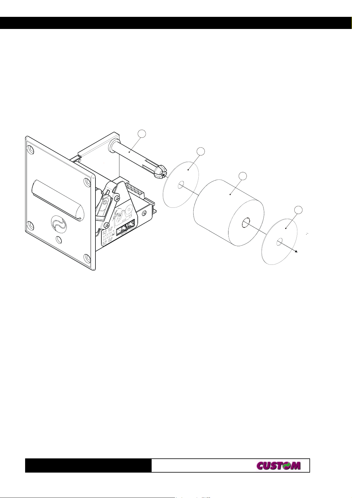
Assembly the control discs with the paper roll as shown in the fig. 1.3.
(Fig.1.3)
1
2
3
2
1.5.2 Changing the paper roll
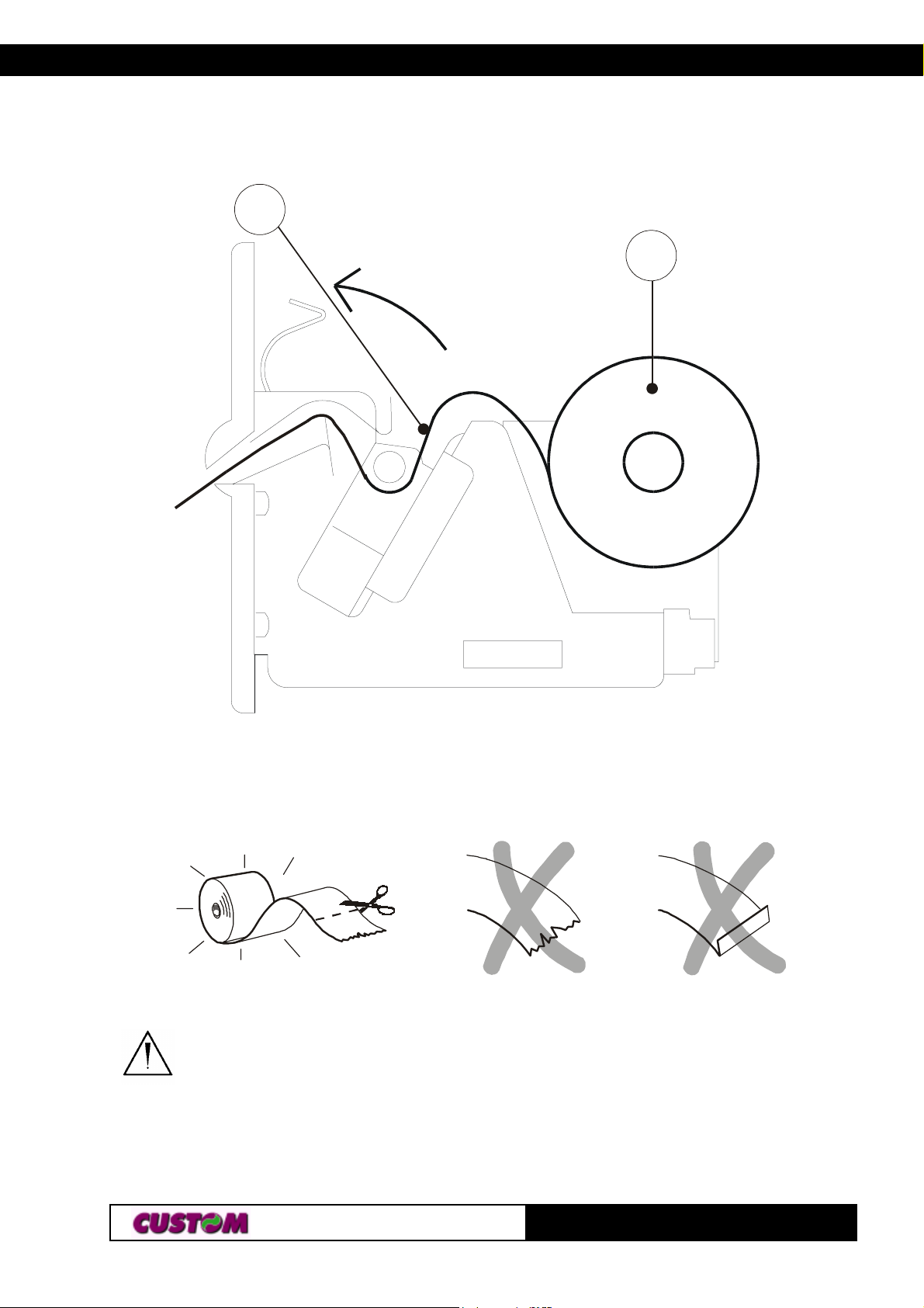
To change the paper roll in the printer, proceed as follows (see the fig. 1.4) :
1) Position the paper roll (1), so that it rotates in the direction shown
(fig.1.4);
2) Insert the end of the paper roll in the print mechanism (2)
and wait until the roll loads automatically;
3) Remove the ticket from the mouth paper output;
TG35/58-T
41-
Page 15
1. INSTALLATION AND OPERATION
2
1
WARNING
Before inserting the paper,
ensure that it is cut evenly.
(Fig.1.4)
(Fig.1.5)
51-
TG35/58-T
Page 16
2. INTERFACES
(Fig.2.1)
J9
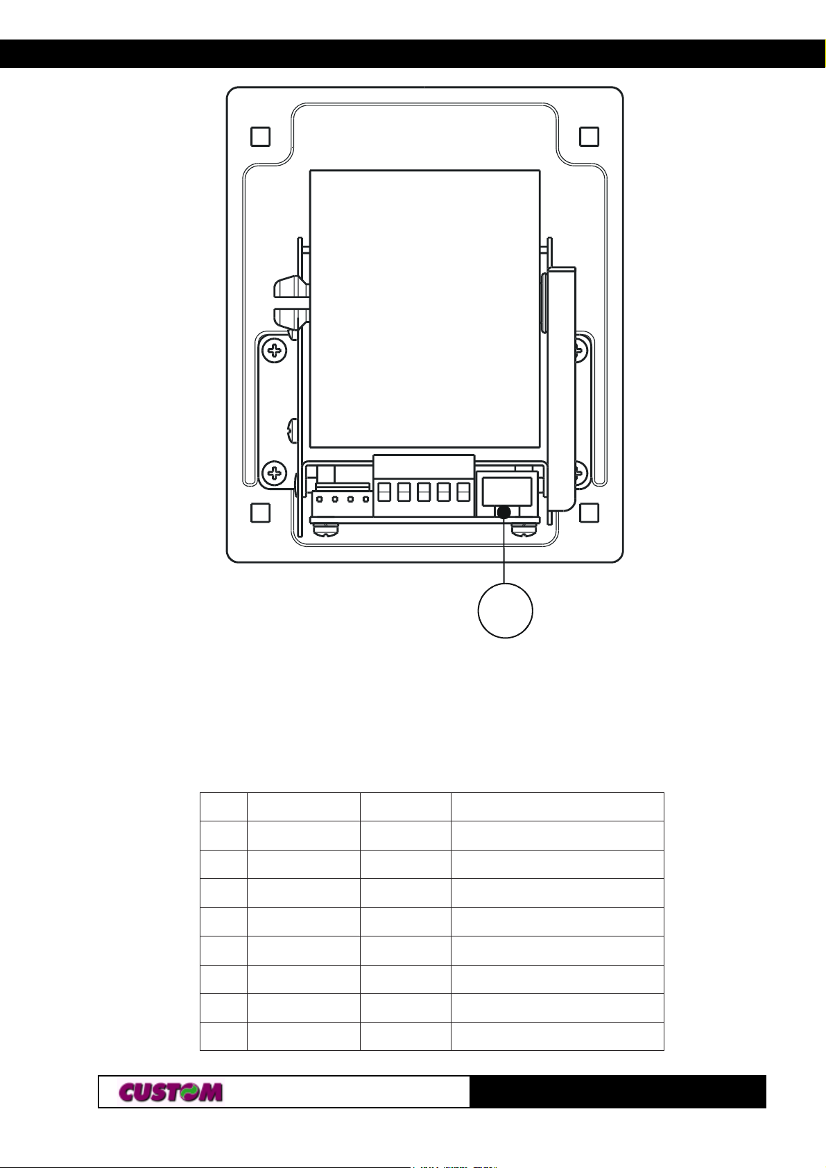
2.1 TTL SERIAL
The printer has a TTL serial interface and is connected by means of a RJ45
connector J9 (see fig. 2.1). In the following table, the signals present on the
connector are listed:
NIPNIP
NIPNIPLANGISLANGIS
NIP
11111
22222
33333
44444
55555
LANGISLANGISTUO/NITUO/NI
LANGIS
CCVTUOV5+
DNG- DNUORG
DXTTUONOISSIMSNARTATAD
DXRNINOITPECERATAD
STRTUODNESOTYDAER
TUO/NITUO/NINOITPIRCSEDNOITPIRCSED
TUO/NI
NOITPIRCSEDNOITPIRCSED
NOITPIRCSED
(Tab.2.1)
66666
77777
88888
NIV+TUOV21+
CN- DETCENNOCTON
CN- DETCENNOCTON
12-
TG35/58-T
Page 17

3. PRINTER FUNCTIONS3. PRINTER FUNCTIONS
3.1 COMMAND DESCRIPTIONS
3.1.1 ESC/POS Emulation
The following table lists all the commands for function management in ESC/
POS Emulation of the printer. The commands can be transmitted to the
printer at any moment, but they will only be carried out when the commands
ahead of them have been executed. The commands are carried out when
the circular buffer is free to do so.
COMMAND DESCRIPTION TABLE
IICSAIICSA
IICSAIICSAXEHXEH
IICSA
XEHXEHnoitpircseDnoitpircseD
XEH
noitpircseDnoitpircseD
noitpircseD
(T ab.3.1)
SB80$ecapskcaB
TH90$batlatnoziroH
FLA0$deefenildnatnirP
RCD0$nruteregairracdnatnirP
nTOEELD)n(40$01$noissimsnartsutatsemit-laeR
NAC81$dettimsnarteniltnerruclecnaC
nPSCSE)n(02$B1$gnicapsedis-thgirretcarahcteS
n!CSE)n(12$B1$edomtnirpteS
HnLn$CSEHnLn42$B1$noitisopetulosbateS
HnLnv(CSEHnLn82$B1$noitisoptnirplacitrevevitalerteS
n-CSE)n(D2$B1$ffo/noedomenilrednunruT
0CSE03$B1$gnicapsenilhcni-8/1tceleS
2CSE23$B1$gnicapsenilhcni-6/1tceleS
n3CSE)n(33$B1$stinumuminimgnisugnicapsenilteS
n4CSE)n(43$B1$edomtpircsteser/teS
n=CSE)n(D3$B1$ecivedtceleS
@CSE04$B1$retnirpezilaitinI
kn...1nDCSE
LUN
00
nECSE)n(54$B1$edomdezisahpmetceleS
nGCSE)n(74$B1$edomekirts-elbuodtceleS
nJCSE)n(A4$B1$repapdeefdnatnirP
nRCSE)n(25$B1$tesretcarahclanoitanretnitceleS
13-
kn...1n44$B1$
snoitisopbatlatnozirohteS
TG35/58-T
Page 18

IICSAIICSA
B
B
IICSAIICSAXEHXEH
IICSA
WCSE75$B1$enilcihpargatnirP
HnLn\CSEHnLnC5$B1$noitisoptnirpevitalerteS
naCSE)n(16$B1$noitacifitsujtceleS
ndCSE)n(46$B1$senilnrepapdeefdnatnirP
nrCSE)n(27$B1$edomgnitnirpderteser/teS
ntCSE)n(47$B1$elbatedocretcarahctceleS
vCSE67$B1$sutatsretnirptimsnarT
nxCSEn87$B1$edomtnerruc/deepstceleS
n{CSE)n(B7$B1$gnitnirpretcarahcnwod-edispulecnac/teS
CSE ⊥ n)n(1C$B1$edomipclecnac/teS
XEHXEHnoitpircseDnoitpircseD
XEH
3. PRINTER FUNCTIONS
noitpircseDnoitpircseD
noitpircseD
HxLxn·CSE
LyHy
nBSG)n(24$D1$
nISG)n(94$D1$DIretnirptimsnarT
HnLnLSGHnLnC4$D1$nigramtfelteS
yxPSGyx05$D1$
HnLnWSGHnLn75$D1$htdiwaeragnitnirpteS
nYSGn95$D1$gnitnirpnithgiehsteS
nZSGnA5$D1$troplairesmorfsetybnevieceR
nrSG)n(27$D1$sutatstimsnarT
n|SG)n(C7$D1$ytisnedgnitnirpteS
LyHy
HxLxnAF$B1$
ogoltnirP
edomgnitnirpesreverkcalb/etihwnruT
ffo/no
stinunoitomlacitrevdnalatnozirohteS
)1edom(
Given below are more detailed descriptions of each command.
SBS
SBSB
S
[Name] Back space
[Format] ASCII BS
Hex 08
Decimal 8
[Description] Moves print position to previous character.
TG35/58-T
23-
Page 19

3. PRINTER FUNCTIONS3. PRINTER FUNCTIONS
H
H
H
L
L
L
[Notes] Can be used to put two characters at the same position.
[Default]
[Reference]
[Example]
THT
THT
T
[Name] Horizontal tab
[Format] ASCII HT
Hex 09
Decimal 9
[Description] Moves the print position to the next horizontal tab position.
[Notes] • Ignored unless the next horizontal tab position has been
set.
• If the command is received when the printing position is at
the right margin, the printer executes print buffer full printing
and horizontal tab processing from the beginning of the next
line.
• Horizontal tab positions are set using ESC D.
[Default]
[Reference] ESC D
[Example]
FLF
FLF
F
[Name] Print and line feed
[Format] ASCII L F
Hex 0A
Decimal 10
[Description] Prints the data in the buffer and feeds one line based on the
current line spacing.
[Notes] • Sets the print position to the beginning of the line.
[Default]
[Reference] ESC 2, ESC 3
[Example]
33-
TG35/58-T
Page 20

3. PRINTER FUNCTIONS
C
C
C
D
D
D
D
D
RCR
RCR
R
[Name] Print and carriage return
[Format] ASCII CR
Hex 0D
Decimal 1 3
[Description] When autofeed is “CR enabled”, this command functions in
the same way as LF, otherwise it is disregarded.
[Notes] • Sets the print position to the beginning of the line.
[Default] See “Autofeed in setup” parameter.
[Reference] LF
[Example]
nTOEEL
nTOEEL
nTOEEL
nTOEEL
nTOEEL
[Name] Real-time status transmission
[Format] ASCII DLE EOT n
Hex 10 04 n
Decimal 1 6 4 n
[Range] 1 ≤ n ≤ 4
[Description] Transmits the selected printer status specified by n in real
time according to the following parameters:
n = 1 transmit printer status
n = 2 transmit off-line status
n = 3 transmit error status
n = 4 transmit paper roll sensor status
n=1: Printer status
tiBnO/ffOxeHlamiceD
0ffO000
1Off 000
2ffO000
ffO000
3
nO808
4nO0161
5- - 6- - 7ffO000
.enil-nO
.enil-ffO
.denifednU
.denifednU
noitcnuF
.ffOotdexiF.desutoN
.ffOotdexiF.desutoN
.ffOotdexiF.desutoN
.nOotdexiF.desutoN
.ffOotdexiF.desutoN
TG35/58-T
43-
Page 21
3. PRINTER FUNCTIONS3. PRINTER FUNCTIONS
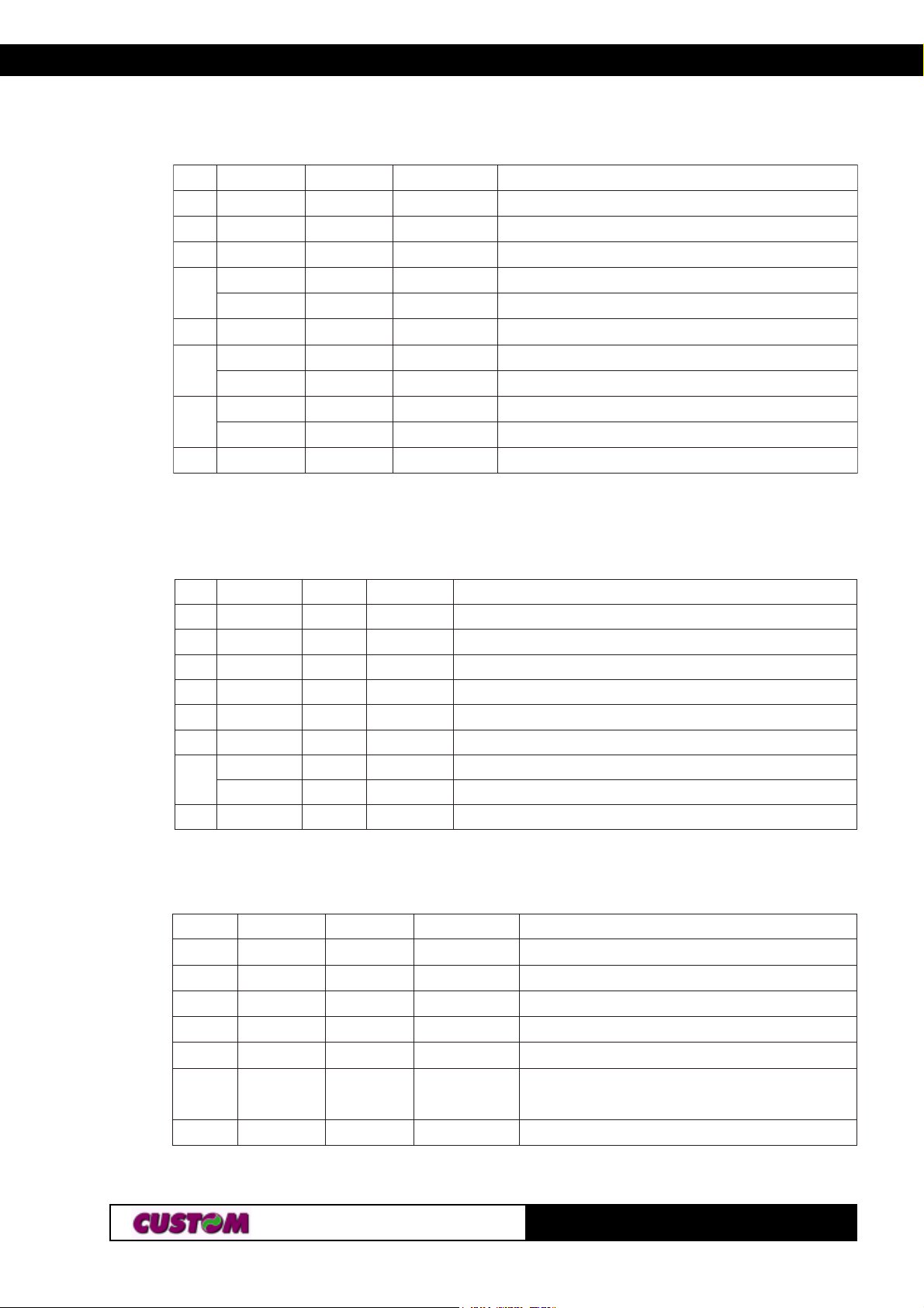
n=2: Off-line status
tiBnO/ffOxeHlamiceD
0ffO000
1Off 000
2ffO000
ffO000
3
nO808
4nO0161
ffO000
5
nO0223
ffO000
6
nO0446
7ffO000
n=3: Error status
tiBnO/ffOxeHlamiceD
0ffO000
1nO202
2ffO000
3- - -
4nO0161
5ffO000
ffO000
6
nO0464
7ffO000
noitcnuF
.ffOotdexiF.desutoN
.ffOotdexiF.desutoN
.ffOotdexiF.desutoN
desserptonnottubDEEF
desserpnottubDEEF
.nOotdexiF.desutoN
.tneserprepaP
.dnerepaP
.rorreoN
.rorrE
.ffOotdexiF.desutoN
noitcnuF
otdexiF.desutoN.ffO
otdexiF.desutoN.nO
otdexiF.desutoN.ffO
.denifednU
.nOotdexiF.desutoN
otdexiF.desutoN.ffO
.rorreelbarevocer-otuaoN
.rorreelbarevocer-otuA
ffOotdexiF.desutoN
n=4: Paper roll sensor status
tiBnO/ffOxeHlamiceD
0ffO000
1nO202
2ffO000
3ffO000
4nO0161
.nOotdexiFdetcetedsidnerepapehT
6,5On60 69
rosnesehtyb
7ffO000
nuFnoitc
.ffOotdexiF.desutoN
.nOotdexiF.desutoN
.ffOotdexiF.desutoN
.ffOotdexiF.desutoN
otdexiF.desutoN.nO
.ffOotdexiF.desutoN
[Notes] • This command is executed when the data buffer is full.
53-
TG35/58-T
Page 22

3. PRINTER FUNCTIONS
C
C
C
E
E
E
E
E
• This status is transmitted whenever data sequence 10H
04H n is received.
• After the paper autoload all buffers (receive and print) are
cleared.
[Default]
[Reference] See tables below.
[Example]
NACNA
NACNA
NA
[Name] Cancel current line transmitted
[Format] ASCII CAN
Hex 18
Decimal 2 4
[Description] Deletes current line transmitted.
[Notes] • Sets the print position to the beginning of the line.
• However, this command does not clear the receive buffer.
[Default]
[Reference]
[Example]
nPSCS
nPSCS
nPSCS
nPSCS
nPSCS
[Name] Set right-side character spacing
[Format] ASCII ESC SP n
Hex 1B 20 n
Decimal 2 7 3 2 n
[Range] 0 ≤ n ≤ 255
[Description] Sets the character spacing for the right side of the character
to [n x horizontal or vertical motion units].
[Notes] • The right character spacing for double-width mode is twice
the normal value.
When the characters are enlarged, the right side character
spacing is m (2 or 4) times the normal value.
• The horizontal and vertical motion units are specified by GS
P. Changing the horizontal or vertical motion units does not
affect the current right side spacing.
TG35/58-T
63-
Page 23
3. PRINTER FUNCTIONS3. PRINTER FUNCTIONS
E
E
E
E
E
• The GS P command can change the horizontal (and vertical) motion unit. However, the value cannot be less than the
minimum horizontal movement amount.
• In standard mode, the horizontal motion unit is used.
• The maximum right side spacing is 255/200 inches.
[Default] n = 0
[Reference] GS P
[Example]
n!CS
n!CS
n!CS
n!CS
n!CS
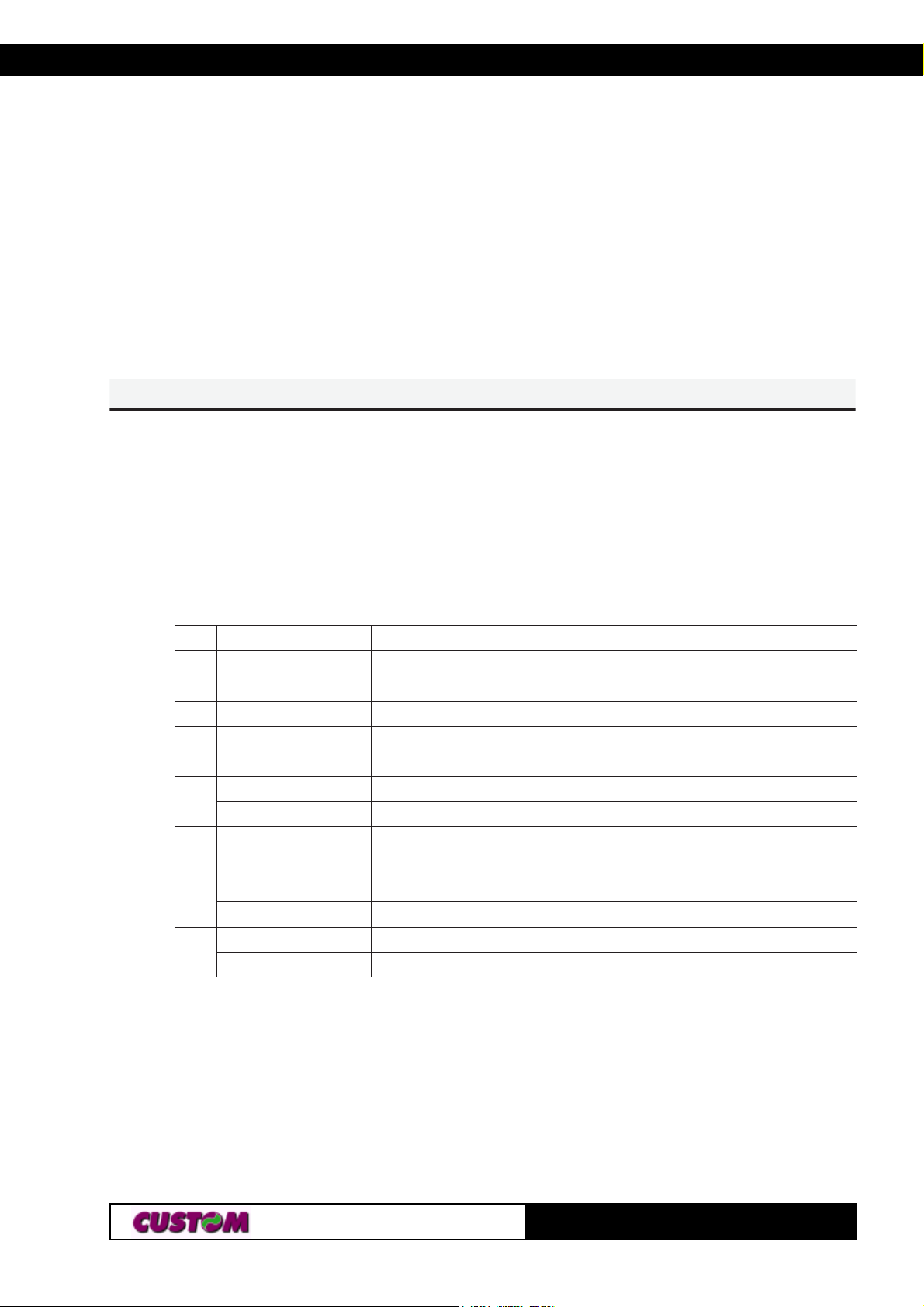
[Name] Select print modes
[Format] ASCII ESC ! n
Hex 1B 21 n
Decimal 2 7 3 3 n
[Range] 0 ≤ n ≤ 255
[Description] Selects print modes using n (see table below):
tiBnO/ffOxeHlamiceD
0- - -
1- - -
2- - -
ffO000
3
nO808
ffO000
4
nO0161
ffO000
5
nO0223
ffO000
6
nO0446
ffO000
7
nO08821
.denifednU
.denifednU
.denifednU
nuFnoitc
.detcelestonedomdednapxE
.detcelesedomdednapxE
.detcelestonedomcilatI
.detcelesedomcilatI
.detcelestonedomenilrednU
.detcelesedomenilrednU
.)x1=thgieh(detcelestonedomthgieh-elbuoD
.)x2=thgieh(detcelesedomthgieh-elbuoD
.)x1=thdiw(detcelestonedomhtdiw-elbuoD
.)x2=thdiw(detcelesedomhtdiw-elbuoD
[Notes] • The printer can underline all characters, but cannot under-
line the spaces set by HT, ESC $, ESC \ and 90° rotated
characters.
• When characters are enlarged to different heights on one
line, the characters are aligned at the baseline or topline (see
GS ~).
• This command resets the left and right margin at default
73-
TG35/58-T
Page 24

value (see GS L, GS W).
E
E
E
E
E
• ESC E can also be used to turn the emphasized mode on/
off. However, the last-received setting command is the effective one.
• ESC - can also be used to turn the underlining mode on/off.
However, the last-received setting command is the effective
one.
• ESC 4 can also be used to turn the italic mode on/off. However, the last-received setting command is the effective one.
• GS ! can also be used to select character height/width.
However, the last-received setting command is the effective
one.
[Default] n = 0
[Reference] ESC -, ESC E, ESC 4, GS !
[Example]
3. PRINTER FUNCTIONS
HnLn$CS
HnLn$CS
HnLn$CS
HnLn$CS
HnLn$CS
[Name] Set absolute print position
[Format] ASCII ESC $ nL nH
Hex 1B 24 nL nH
Decimal 2 7 36 nL nH
[Range] 0 ≤ nL ≤ 255
0 ≤ nH ≤ 255
[Description] Sets the distance from the beginning of the line to the posi-
tion at which subsequent characters are to be printed.
The distance from the beginning of the line to the print posi-
tion is [(nL + nH × 256) × (vertical or horizontal motion unit)]
inches.
[Notes] • Settings outside the specified printable area are ignored.
• The horizontal and vertical motion unit are specified by
GS P.
• GS P can change the horizontal (and vertical) motion unit.
However, the value cannot be less than the minimum horizon-
tal movement amount.
• In standard mode, the horizontal motion unit (x) is used.
• If the setting is outside the printing area width, it sets the
absolute print position, but the left or right margin is set at
default value.
TG35/58-T
83-
Page 25

3. PRINTER FUNCTIONS3. PRINTER FUNCTIONS
E
E
E
E
E
E
E
E
E
E
[Default]
[Reference] ESC \, GS P
[Example]
HnLnv(CS
HnLnv(CS
HnLnv(CS
HnLnv(CS
HnLnv(CS
[Name] Set relative vertical print position
[Format] ASCII ESC ( v nL nH
Hex 1B 28 76 nL nH
Decimal 2 7 1 0 118 nL nH
[Range] 0 ≤ nL ≤ 255
[Description] Sets the print vertical position based on the current position
by using the horizontal or vertical motion unit.
•This command sets the distance from the current position to
[( nL + nH x 256) x ( horizontal or vertical motion unit )].
[Notes] •When the starting position is specified by N motion unit to
the bottom:
nL + nH x 256=N
When the starting position is specified by N motion unit to the
top (negative direction), use the complement of 65536:
nL + nH x 256=65536 - N
[Default]
[Reference]
[Example]
n-CS
n-CS
n-CS
n-CS
n-CS
[Name] Turn underline mode on/off
[Format] ASCII ESC - n
Hex 1B 2D n
Decimal 2 7 4 5 n
[Range] 0 ≤ n ≤ 2, 48 ≤ n ≤ 50
[Description] Turns underline mode on or off, based on the following val-
ues of n:
n = 0, 48 Turns off underline mode
n = 1, 49 Turns on underline mode (1-dot thick)
n = 2, 50 Turns on underline mode (2-dot thick)
93-
TG35/58-T
Page 26

3. PRINTER FUNCTIONS
E
E
E
E
E
E
[Notes] • The printer can underline all characters, but cannot under-
line the space set by HT and right-side character spacing.
• The printer cannot underline 90° rotated characters and
white/black inverted characters.
• When underline mode is turned off by setting the value of n
to 0 or 48, the data which follows is not underlined.
• Underline mode can also be turned on or off by using
ESC !. Note, however, that the last received command is the
effective one.
[Default] n=0
[Reference] ESC !
[Example]
0CSE0CS
0CSE0CS
0CS
[Name] Select 1/8-inch line spacing
[Format] ASCII ESC 0
Hex 1B 30
Decimal 2 7 48
[Description] Selects 1/8-inch line spacing
[Notes]
[Default]
[Reference] ESC 2, ESC 3
[Example]
2CSE2CS
2CSE2CS
2CS
[Name] Select 1/6-inch line spacing
[Format] ASCII ESC 2
Hex 1B 32
Decimal 2 7 5 0
[Description] Selects 1/6-inch line spacing.
[Notes]
[Default]
[Reference] ESC 0, ESC 3
[Example]
TG35/58-T
103-
Page 27

3. PRINTER FUNCTIONS3. PRINTER FUNCTIONS
E
E
E
E
E
E
E
E
E
E
n3CS
n3CS
n3CS
n3CS
n3CS
[Name] Set line spacing
[Format] ASCII ESC 3 n
Hex 1B 33 n
Decimal 2 7 5 1 n
[Range] 0 ≤ n ≤ 255
[Description] Sets line spacing to [ n × (vertical or horizontal motion unit)]
inches.
[Notes] • The horizontal and vertical motion unit are specified by
GS P. Changing the horizontal or vertical motion unit does not
affect the current line spacing.
• The GS P command can change the horizontal (and verti-
cal) motion unit. However, the value cannot be less than the
minimum vertical movement amount.
• In standard mode, the vertical motion unit is used.
• The maximum line spacing is n = 255 ( ≅ 32mm).
[Default] n = 32 (1/6 inch)
[Reference] ESC 0, ESC 2, GS P
[Example]
n4CS
n4CS
n4CS
n4CS
n4CS
[Name] Set/reset italic mode
[Format] ASCII ESC 4 n
Hex 1B 34 n
Decimal 27 52 n
[Range] 0 ≤ n ≤ 1, 48 ≤ n ≤ 49
[Description] Turns italic mode on or off, based on the following values of
n:
nnoitcnuF
84,0edomcilatiffosnruT
94,1edomcilatinosnruT
[Notes] • The printer can print any character in italic mode.
• When italic mode is turned off by setting the value of n to 0
or 48, the data which follows is printed in normal mode.
113-
TG35/58-T
Page 28

3. PRINTER FUNCTIONS
E
E
E
E
E
E
E
E
• Italic mode can also be turned on or off using ESC !. Note,
however, that the last received command is the effective one.
[Default] n = 0
[Reference] ESC !
[Example]
n=CS
n=CS
n=CS
n=CS
n=CS
[Name] Select peripheral device
[Format] ASCII ESC = n
Hex 1B 3D n
Decimal 2 7 6 1 n
[Range] 0 ≤ n ≤ 255
[Description] Select the device to which the host computer sends data,
using n as follows:
tiBnO/ffOxeHlamiceD
ffO000
0
nO01 1
1- - 2- - 3- - 4- - 5- - 6- - 7- - -
delbasidretnirP
delbaneretnirP
denifednU
denifednU
denifednU
denifednU
denifednU
denifednU
denifednU
noitcnuF
[Notes] • When the printer is disabled, it ignores all transmitted data
until the printer is enabled through this command.
[Default] n = 1
[Reference]
[Example]
@CSE@CS
@CSE@CS
@CS
[Name] Initialize printer
[Format] ASCII ESC @
Hex 1B 40
Decimal 27 6 4
TG35/58-T
123-
Page 29

3. PRINTER FUNCTIONS3. PRINTER FUNCTIONS
E
E
E
E
E
[Description] Clears the data in the print buffer and resets the printer mode
to that in effect when power was turned on.
[Notes] • The data in the receiver buffer is not cleared.
• The macro definitions are not cleared.
[Default]
[Reference]
[Example]
LUN]kn...1n[DCS
LUN]kn...1n[DCS
LUN]kn...1n[DCS
LUN]kn...1n[DCS
LUN]kn...1n[DCS
[Name] Set horizontal tab positions
[Format] ASCII ESC D n1...nk NUL
Hex 1B 44 n1...nk 00
Decimal 2 7 6 8 n1...nk 0
[Range] 1 ≤ n ≤ 255
0 ≤ k ≤ 32
[Description] Sets horizontal tab positions
• n specifies the column number for setting a horizontal tab
position calculated from the beginning of the line.
• k indicates the total number of horizontal tab positions to be
set.
[Notes] • The horizontal tab position is stored as a value of [character
width x n] measured from the beginning of the line. The character width includes the right-side character spacing and
double-width characters are set with twice the width of normal
characters.
• This command cancels previous tab settings.
• When setting n = 8, the print position is moved to column 9,
by sending HT.
• Up to 32 tab positions ( k = 32) can be set. Data exceeding
32 tab positions is processed as normal data.
• Send [ n ] k in ascending order and place a 0 NUL code at
the end. When [ n ] k is less than or equal to the preceding
value [ n ] k-1, the setting is complete and the data which
follows is processed as normal data.
• ESC D NUL cancels all horizontal tab positions.
• The previously specified horizontal tab position does not
change, even if the character width is modified.
[Default] Default tab positions are set at intervals of 8 characters (col-
133-
TG35/58-T
Page 30

3. PRINTER FUNCTIONS
E
E
E
E
E
E
E
E
E
E
umns 9, 17, 25, …) for Font A when the right-side character
spacing is 0.
[Reference] HT
[Example]
nECS
nECS
nECS
nECS
nECS
[Name] Turn emphasized mode on/off
[Format] ASCII ESC E n
Hex 1B 45 n
Decimal 2 7 69 n
[Range] 0 ≤ n ≤ 255
[Description] Turns emphasized mode on/off.
• When the LSB of n is 0, the emphasized mode is off.
• When the LSB of n is 1, the emphasized mode is on.
[Notes] • Only the LSB of n is effective.
• ESC ! also turns on and off the emphasized mode. How-
ever, the last received command is the effective one.
[Default] n = 0
[Reference] ESC !
[Example]
nGCS
nGCS
nGCS
nGCS
nGCS
[Name] Turn double-strike mode on/off
[Format] ASCII ESC G n
Hex 1B 47 n
Decimal 2 7 71 n
[Range] 0 ≤ n ≤ 255
[Description] Turns double-strike mode on or off.
• When the LSB of n is 0, the double-strike mode is off.
• When the LSB of n is 1, the double-strike mode is on.
[Notes] • Only the LSB of n is effective.
• Printer output is the same in double-strike and emphasized
mode.
[Default] n = 0
[Reference] ESC E
TG35/58-T
143-
Page 31

3. PRINTER FUNCTIONS3. PRINTER FUNCTIONS
E
E
E
E
E
E
E
E
E
E
[Example]
nJCS
nJCS
nJCS
nJCS
nJCS
[Name] Print and paper feed
[Format] ASCII ESC J n
Hex 1B 4A n
Decimal 2 7 74 n
[Range] 0 ≤ n ≤ 255
[Description] Prints the data in the print buffer and feeds the paper [ n ×
(vertical or horizontal motion unit)] inches.
[Notes] • After printing has been completed, this command sets the
print starting position to the beginning of the line.
• The paper feed amount set by this command does not af-
fect the values set by ESC 2 or ESC 3.
• The horizontal and vertical motion units are specified by
GS P.
• GS P can change the vertical (and horizontal) motion unit.
However, the value cannot be less than the minimum vertical
movement amount.
• In standard mode, the vertical motion unit is used.
• The maximum paper feed amount is 31.8 mm.
[Default]
[Reference] GS P
[Example]
nRCS
nRCS
nRCS
nRCS
nRCS
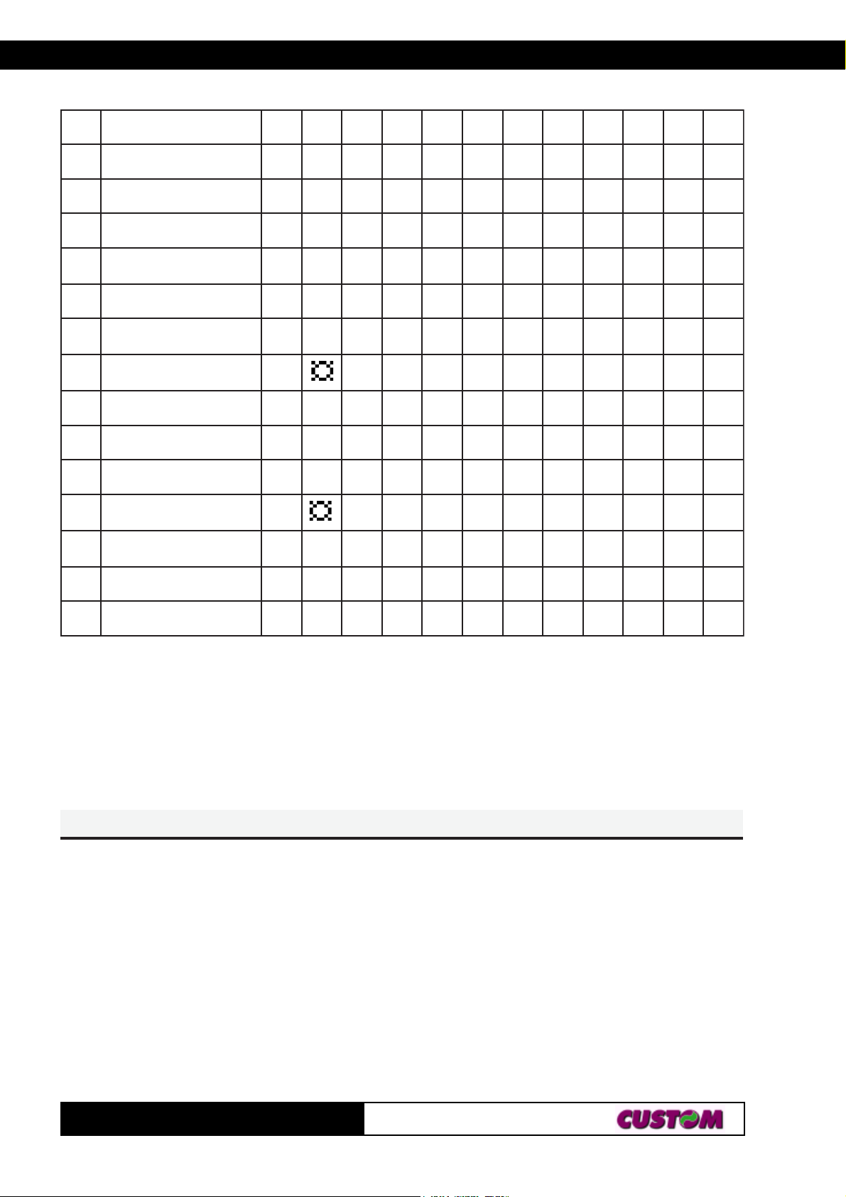
[Name] Select an international character set
[Format] ASCII ESC R n
Hex 1B 52 n
Decimal 27 8 2 n
[Range] 0 ≤ n ≤ 12
[Description] Selects the international character set n according to the
table below:
153-
TG35/58-T
Page 32
3. PRINTER FUNCTIONS
E
E
E
E
E
xeH324204B5C5D5E506B7C7D7E7
ntesretcarahC
0.A.S.U#$@[\]^`{|}~
1cnarF e #$à°ç§^`éùè"
2namreGy#$§ÄÖÜ^`äöü
β
3modgniKdetinU£$@[\]^`{|}~
4kramneDI#$@Æ∅Å^ `æ
φ
å~
5nedewS # ЙДЦЕЬйдцеь
6ylatI #$@°\ и^щатим
7niapS1 tP$@iÑ¿^`"ñ}~
8napaJ#$@[¥]^`{|}~
9yawroN#ÉÆ
01kramneDII#$ÉÆ∅ÅÜéæ
ÅÜéæ
∅
φ
φ
åü
åü
112niapS#$àiÑ¿é‘íñöü
21aciremAhtuoS#$àiÑ¿éùíñöü
[Default] n = 0
[Reference]
[Example]
HnLn\CS
HnLn\CS
HnLn\CS
HnLn\CS
HnLn\CS
[Name] Set relative print position
[Format] ASCII ESC \ nL nH
Hex 1B 5C nL nH
Decimal 2 7 92 nL nH
[Range] 0 ≤ nL ≤ 255
0 ≤ nH ≤ 255
[Description] Sets the print starting position based on the current position
by using the horizontal or vertical motion unit.
Sets the distance from the current position to [(nL+ nH × 256)
TG35/58-T
163-
Page 33

3. PRINTER FUNCTIONS3. PRINTER FUNCTIONS
E
E
E
E
E
× (horizontal or vertical motion unit)].
[Notes] • Any setting that exceeds the printable area is ignored.
• When the starting position is specified by n motion units to
the right:
nL + nH × 256 = n
When the starting position is specified by n motion units to
the left (negative direction), use the complement of 65536:
nL + nH × 256 = 65536 – n
• If setting exceeds the printing area width, the left or right
margin is set to the default value.
• The horizontal and vertical motion unit are specified by
GS P.
• GS P can change the horizontal (and vertical) motion units.
However, the value cannot be less than the minimum horizontal movement amount.
• In standard mode, the horizontal motion unit is used.
[Default]
[Reference] ESC $, GS P
[Example]
naCS
naCS
naCS
naCS
naCS
[Name] Select justification
[Format] ASCII ESC a n
Hex 1B 61 n
Decimal 2 7 97 n
[Range] 0 ≤ n ≤ 2, 48 ≤ n ≤ 50
[Description] Aligns all data in one line to the specified position.
n selects the type of justification as follows:
n Justification
0, 48 Flush left
1, 49 Centered
2, 50 Flush right
[Notes] • This command is only enabled when inserted at the begin-
ning of a line.
• Lines are justified within the specified printing area.
• Spaces set by HT, ESC $ and ESC \ will be justified ac-
cording to the previously-entered mode.
[Default] n = 0
173-
TG35/58-T
Page 34

3. PRINTER FUNCTIONS
E
E
E
E
E
E
E
E
E
E
[Reference]
[Example] Flush left Centered Flush right
ABC
ABCD
ABCDE
ndCS
ndCS
ndCS
ndCS
ndCS
ABC
ABCD
ABCDE
ABC
ABCD
ABCDE
[Name] Print and feed paper n rows
[Format] ASCII ESC d n
Hex 1B 64 n
Decimal 2 7 100 n
[Range] 0 ≤ n ≤ 200
[Description] Prints the data in the print buffer and feeds the paper n rows.
[Notes] • Sets the print starting position at the beginning of the line.
• This command does not affect the line spacing set by
ESC 2 or ESC 3.
• The maximum paper feed amount is 200 rows. Even if a
paper feed amount of more than 200 rows is set, the printer
feeds the paper only 200 rows.
[Default]
[Reference] ESC 2, ESC 3
[Example]
nrCS
nrCS
nrCS
nrCS
nrCS
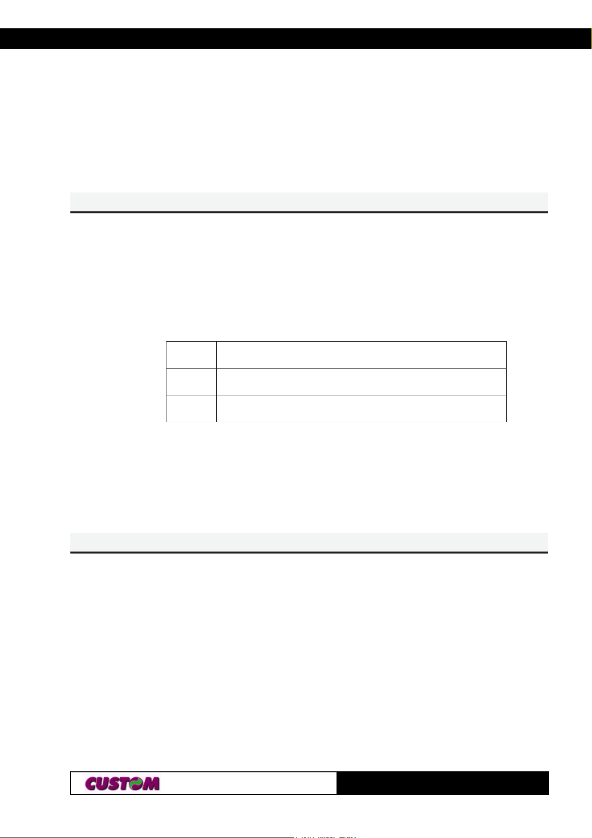
[Name] Set/reset red printing mode
[Format] ASCII ESC r n
Hex 1B 72 n
Decimal 2 7 114 n
[Range] 0 ≤ n ≤ 1, 48 ≤ n ≤ 49
[Description] Sets and resets red printing mode.
n Function
0, 48 Reset red printing mode
1, 49 Set red printing mode
[Notes] • The printer prints only entire lines in red, not individual char-
TG35/58-T
183-
Page 35
3. PRINTER FUNCTIONS3. PRINTER FUNCTIONS
E
E
E
E
E
E
E
E
acters.
• The printer prints red only if enabled (see Setup).
[Default] n = 0
[Reference]
[Example]
ntCS
ntCS
ntCS
ntCS
ntCS
[Name] Select character code table
[Format] ASCII ESC t n
Hex 1B 74 n
Decimal 27 116 n
[Range] n = 0, 255
[Description] Selects a page n from the character code table, as follows:
negaP
0)]eporuEdradnatS,.A.S.U[734CP(0
552egapecapS
[Notes]
[Default] n = 0
[Reference] See character code tables
[Example]
vCSEvCS
vCSEvCS
vCS
[Name] Transmit paper sensor status
[Format] ASCII ESC v
Hex 1B 76
Decimal 2 7 118
[Description] When this command is received, transmit the current status
of the paper sensor.
The status to be transmitted is shown in the table below:
193-
TG35/58-T
Page 36
3. PRINTER FUNCTIONS
E
E
E
E
E
tiBnO/ffOxeHlamiceD
01,ffO000
ffO000
3,2
nO)C0()21(
4ffO000
5- - 6- - 7ffO000
denifednU
denifednU
noitcnuF
.ffOotdexiF.desutoN
:rosnesdne-repaP
tneserprepaP
:rosnesdne-repaP
tneserptonrepaP
.ffOotdexiF.desutoN
.ffOotdexiF.desutoN
[Notes] • This command is executed immediately, even when the
data buffer is full (Busy ).
• After the paper autoload all buffers (receive and print) are
cleared.
[Default]
[Reference] DLE EOT
[Example]
nxCS
nxCS
nxCS
nxCS
nxCS
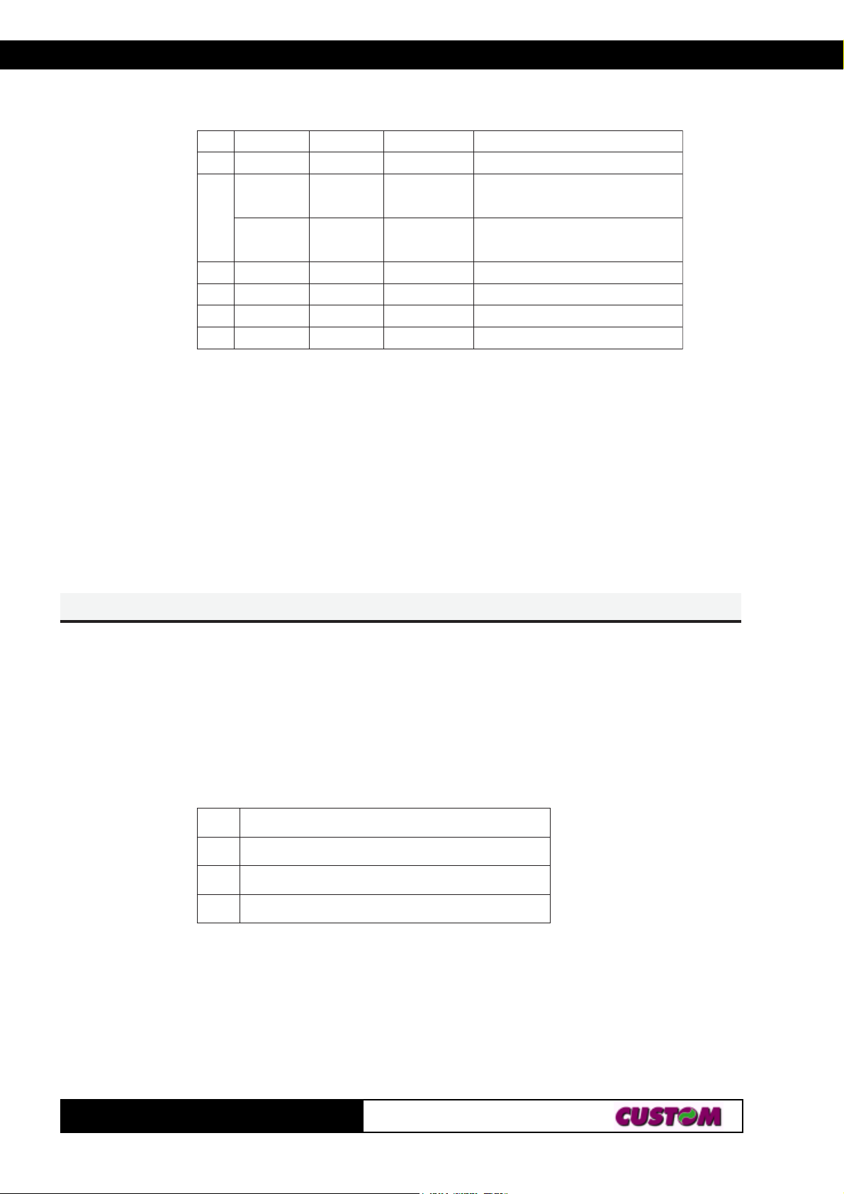
[Name] Selects speed/current mode
[Format] ASCII ESC x n
Hex 1B 78 n
Decimal 2 7 120 n
[Range] 0 ≤ n ≤ 2
[Description] Selects printing speed/current mode.
nnoitcnuF
0tnerrucwol,deepswoL
1edomlamroN
2tnerruchgih,deepshgiH
[Notes]
[Default] n = 0
[Reference]
[Example]
TG35/58-T
203-
Page 37
3. PRINTER FUNCTIONS3. PRINTER FUNCTIONS
E
E
E
E
E
E
E
E
E
E
n{CS
n{CS
n{CS
n{CS
n{CS
[Name] Turn upside-down printing mode on/off
[Format] ASCII ESC { n
Hex 1B 7B n
Decimal 2 7 123 n
[Range] 0 ≤ n ≤ 255
[Description] Turns upside-down printing mode on or off.
• When the LSB of n is 0, the upside-down printing mode is
off.
• When the LSB of n is 1, the upside-down printing mode is
on.
[Notes] • Only the LSB of n is effective.
• This command is valid only if entered at the beginning of a
line.
• In upside-down printing mode, the printer rotates the line to
be printed 180° and then prints it.
[Default] n = 0
[Reference]
[Example]
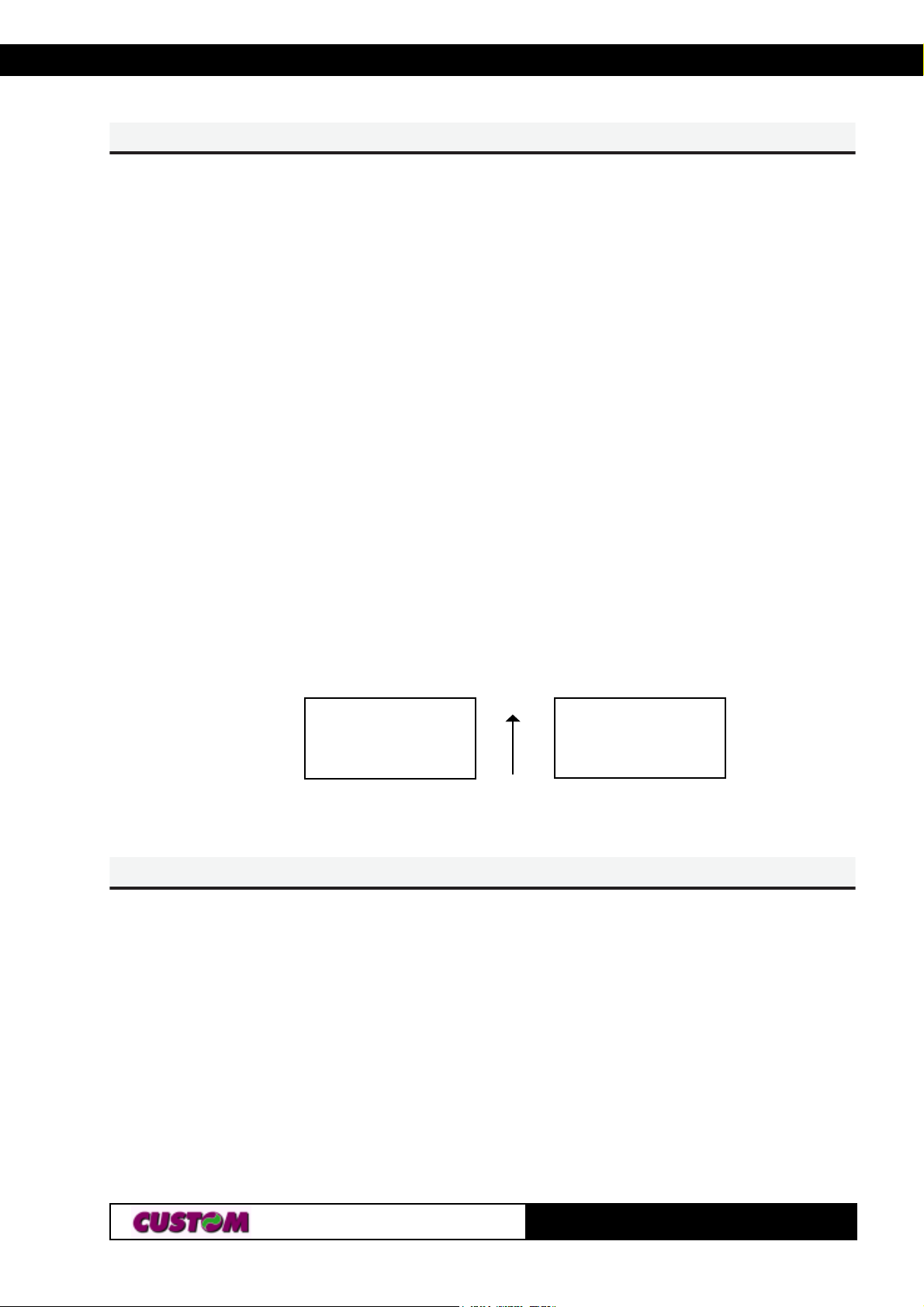
Upside-down printing Off Upside-down printing O
ABCDEFG
0123456
Printing direction
LyHyLxHxn·CS
LyHyLxHxn·CS
LyHyLxHxn·CS
LyHyLxHxn·CS
LyHyLxHxn·CS
[Name] Print logo (384 x 585 dots).
[Format] ASCII ESC · n xH xL yH yL
Hex 1B FA n xH xL yH yL
Decimal 2 7 250 n xH xL yH yL
[Range] 0 ≤ n ≤ 255
ABCDEFG
0123456
0 ≤ xH, xL, yH, yL ≤ 255
[Description] Prints graphic logo from flash.
xL + xH × 256 specifies the starting dotline ( 1 ÷ 85).
yL + yH × 256 specifies the number of lines to print.
[Notes] • If (xL + (xH × 256)) > 85 the printer does not execute the
213-
TG35/58-T
Page 38
3. PRINTER FUNCTIONS
G
G
G
t
ti
command.
• If ( xL + ( xH × 256 ) + yL +( yH × 256 ))> 85 the printer
prints only 85 - xL + ( xH × 256 ) +1 dotline.
[Default]
[Reference]
[Example] To print from ram bank dotline 10 to dotline 64, send:
1BH FAH 00H 00H 0AH 00H 40H
n!SGn!S
n!SGn!S
n!S
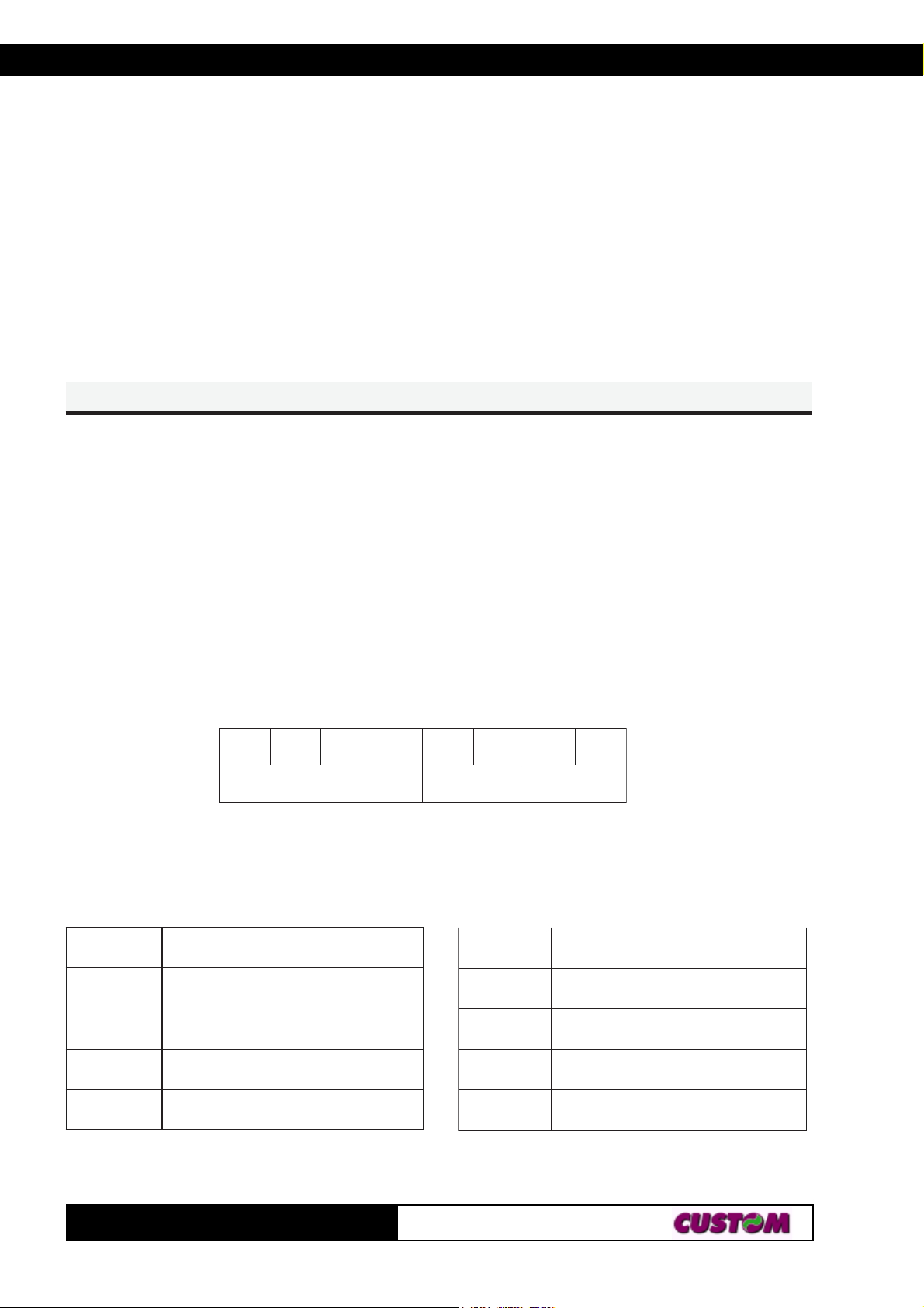
[Name] Select character size
[Format] ASCII G S ! n
Hex 1D 21 n
Decimal 29 3 3 n
[Range] 0 ≤ n ≤ 255
[Description] Selects character height and width, as follows:
• Bits 0 to 3 low Nibble: to select character height (see table
2).
• Bits 4 to 7 Higth Nibble: to select character width (see table
1).
tib01tib2tibtib3tib4tib5tib6
thgiehhtdiw
b7
1elbaThtdiWretcarahCtceleS
)elbbiNthgih(
xeHhtdiW
xeHthgieH
hgiehretcarahctceleS2elbaT
)elbbiNwoL(
0x lamron(1x1=htdiw)
x12 )x2=htdiw(
x0 (1)x1=thgiehlamron)
1x)x2=thgieh(2
x2)x3=htdiw(3
xF-x3(1lamronx1=htdiw)
[Notes] • This command is effective for all characters (except HRI
TG35/58-T
2x)x3=thgieh(3
Fx-3x)x1=thgiehlamron(1
223-
Page 39

3. PRINTER FUNCTIONS3. PRINTER FUNCTIONS
G
G
G
G
characters).
• If n falls outside the defined range, this command is ignored.
• Characters enlarged to different heights on the same line
are aligned at the baseline or topline (see GS ~).
• ESC ! can also be used to select character size. However,
the setting of the last received command is the effective one.
[Default] n = 0
[Reference] ESC !
[Example]
nBSGnBS
nBS
nBS
nBS
[Name] Turn white/black reverse printing mode on/off
[Format] ASCII GS B n
Hex 1D 42 n
Decimal 2 9 66 n
[Range] 0 ≤ n ≤ 255
[Description] Turns white/black reverse printing mode on or off.
• When the LSB of n is 0, white/black reverse printing is
turned off.
• When the LSB of n is 1, white/black reverse printing is
turned on.
[Notes] • Only the LSB di n is effective.
• This command is available for both built-in and user-defined
characters.
• This command does not affect bit image, downloaded bit
image, bar code, HRI characters and spacing skipped by HT,
ESC $ and ESC \.
• This command does not affect white space between lines.
• White/black reverse mode has a higher priority than under-
line mode. Even if underline mode is on, it will be disabled
(but not cancelled) when white/black reverse mode is se-
lected.
[Default] n = 0
[Reference]
[Example]
233-
TG35/58-T
Page 40
3. PRINTER FUNCTIONS
G
G
G
nISGnIS
nISGnIS
nIS
[Name] Transmit printer ID
[Format] ASCII G S I n
Hex 1D 49 n
Decimal 29 7 3 n
[Range] 1 ≤ n ≤ 3, 49 ≤ n ≤ 51
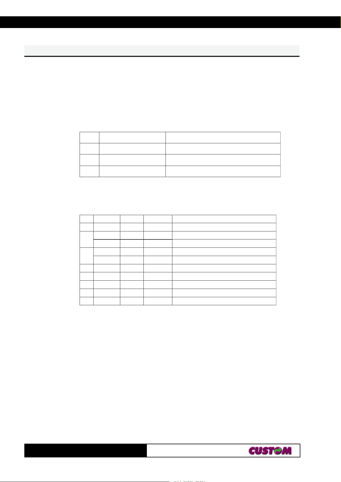
[Description] Transmits the printer ID specified by n follows:
nDIretnirPnoitacificepS
94,1DIledomretnirP)85-53GT(H61
05,2DIepyTwolebelbateeS
15,3DInoisrevMOR)retcarahc4(noisrevMORnosdnepeD
n = 2, Type ID
tiBnO/ffOxeHlamiceD
0
1
2
3- - -
4ffO000
5- - 6- - 7ffO000
ffO000 detroppustonsedocretcarahcetyb-2
ffO000 deilppustonrettucotuA
nO202
ffO000 lebalo/wrepaplamrehT
nO404
denifednU
denifednU
denifednU
noitcnuF
deilppusrettucotuA
lebal/wrepaplamrehT
.ffOotdexiF.desutoN
.ffOotdexiF.desutoN
[Notes] • This command is executed when the data is processed in
the data buffer. Therefore, there could be a time lag between
command reception and data transmission, depending on
data buffer status.
[Default]
[Reference]
[Example]
TG35/58-T
243-
Page 41

3. PRINTER FUNCTIONS3. PRINTER FUNCTIONS
G
G
G
G
G
HnLnL S
HnLnL S
HnLnL S
HnLnL S
HnLnL S
[Name] Set left margin
[Format] ASCII GS L nL nH
Hex 1D 4C nL nH
Decimal 2 9 76 nL nH
[Range] 0 ≤ nL, nH ≤ 255
[Description] Sets the left margin.
• The left margin is set to [(nL + nH × 256) × (horizontal mo-
tion unit)] inches.
Printable
Left margin Printing area width
[Notes] • This command is enabled only if set at the beginning of the
line.
• If the setting exceeds the printable area, the maximum
value of the printable area is used.
• If the left margin + printing area width is greater than the
printable area, the printing area width is set at maximum
value.
• The horizontal and vertical motion unit are specified by
GS P. Changing the horizontal or vertical motion unit does not
affect the current left margin.
• The GS P command can change the horizontal (and verti-
cal) motion unit.
• However, the value cannot be less than the minimum hori-
zontal movement amount and it must be in even units of the
minimum horizontal movement amount.
[Default] If font A : nL = nH = 0
If font B : nL = 14 nH = 0
[Reference] GS P, GS W
[Example]
253-
TG35/58-T
Page 42

3. PRINTER FUNCTIONS
G
G
G
G
G
G
G
G
G
G
yxPS
yxPS
yxPS
yxPS
yxPS
[Name] Set horizontal and vertical motion units
[Format] ASCII GS P x y
Hex 1D 50 x y
Decimal 2 9 80 x y
[Range] x = 100, 200
y = 100, 200
[Description] Sets the horizontal and vertical motion units to 1/x inch and
1/y inch respectively.
When x is set to 0, the default setting value is used.
When y is set to 0, the default setting value is used.
[Notes] • The horizontal direction is perpendicular to the paper feed
direction.
• In standard mode, the following commands use x or y, regardless of character rotation (upside-down or 90° clockwise
rotation):
Q Commands using x : ESC SP, ESC $, ESC \, GS L, GS
W.
R Commands using y : ESC 3, ESC J.
• This command does not affect the previously specified
values.
• The calculated result from combining this command with
others is truncated to the minimum value of the mechanical
pitch or an exact multiple of that value.
[Default] x = 200, y = 200
[Reference] ESC SP, ESC $, ESC \, ESC 3, ESC J, GS L, GS W.
[Example]
HnLnWS
HnLnWS
HnLnWS
HnLnWS
HnLnWS
[Name] Set printing area width
[Format] ASCII GS W nL nH
Hex 1D 57 nL nH
Decimal 2 9 87 nL nH
[Range] 0 ≤ nL, nH ≤ 255
[Description] Sets the printing area width to the area specified by nL and
nH.
• The left margin is set to [(nL + nH × 256) × (horizontal mo-
TG35/58-T
263-
Page 43

3. PRINTER FUNCTIONS3. PRINTER FUNCTIONS
G
G
G
tion unit)] inches.
Printable area
Left margin Printing area width
[Notes] • This command is only enabled if set at the beginning of the
line.
• If the right margin is greater than the printable area, the
printing area width is set at maximum value.
• If the printing area width = 0, it is set at the maximum value.
• The horizontal and vertical motion units are specified by
GS P. Changing the horizontal or vertical motion unit does not
affect the current left margin.
• The GS P command can change the horizontal (and vertical) motion unit.
• However, the value cannot be less than the minimum horizontal movement amount and it must be in even units of the
minimum horizontal movement amount.
[Default] If font A : nL = 192 nH = 1
If font B : nL = 164 nH = 1
[Reference] GS L, GS P
[Example]
nYSGnYS
nYSGnYS
nYS
[Name] Sets height in printing.
[Format] ASCII GS Y n
Hex 1D 59 n
Decimal 2 9 89 n
[Description] Sets height during printing based on following values of n:
When you print a dot line if
n=0 height is set to one
n
≠ 0 (default value) height is set to two
[Notes] When n ≠ 0 (default value) each dotline is twice replicated
273-
TG35/58-T
Page 44

3. PRINTER FUNCTIONS
G
G
G
G
G
G
[Default] n ≠ 0
[Reference]
[Example]
nZSGnZS
nZSGnZS
nZS
[Name] Receive n bytes from serial port
[Format] ASCII GS Z n
Hex 1D 5A n
Decimal 2 7 90 n
[Description] Receives n bytes from serial port and prints them in graphic
mode
[Notes] Max value of n is 58
[Default]
[Reference]
[Example]
nrSGnrS
nrSGnrS
nrS
[Name] Transmit status
[Format] ASCII GS r n
Hex 1D 72 n
Decimal 2 9 11 4 n
[Range] n = 1, 2, 49, 50
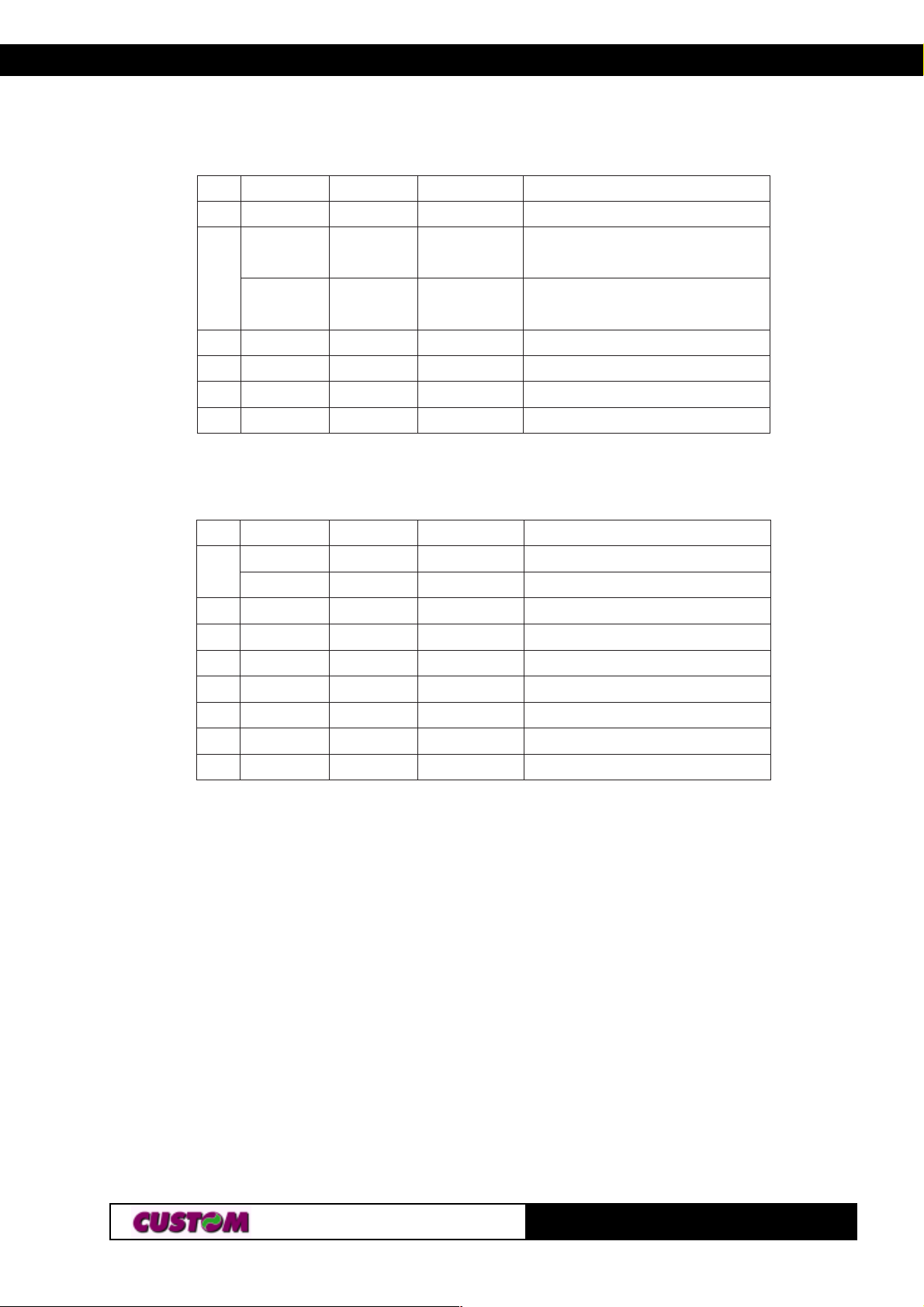
[Description] Transmits the status specified by n as follows:
n Function
1, 49 Transmits paper sensor status (as for ESC v).
2, 50 Transmits connector drawer status.
TG35/58-T
283-
Page 45
3. PRINTER FUNCTIONS3. PRINTER FUNCTIONS
Paper sensor status (n = 1, 49)
tiBnO/ffOxeHlamiceD
01,ffO000
ffO000
3,2
nO)C0()21(
4ffO000
5- - 6- - 7ffO000
Connector drawer status (n = 2, 50)
tiBnO/ffOxeHlamiceD
ffO000
0
nO101
1- - -
2- - 3- - 4ffO000
5- - 6- - 7ffO000
noitcnuF
.ffOotdexiF.desutoN
:rosnesdne-repaP
tneserprepaP
:rosnesdne-repaP
tneserptonrepaP
.ffOotdexiF.desutoN
denifednU
denifednU
.ffOotdexiF.desutoN
noitcnuF
levelwol3niP
levelhgih3niP
denifednU
denifednU
denifednU
.ffOotdexiF.desutoN
denifednU
denifednU
.ffOotdexiF.desutoN
[Notes] • This command is executed when the data is processed in
the data buffer. Therefore, there may be a time lag between
receiving the command and transmitting the status, depend-
ing on data buffer status.
[Default]
[Reference] DLE EOT, ESC v
[Example]
293-
TG35/58-T
Page 46

n|SGn|S
G
G
n|SGn|SG
n|S
[Name] Set printing density
[Format] ASCII GS | n
Hex 1D 7C n
Decimal 2 9 124 n
[Range] 0 ≤ n ≤ 4, 48 ≤ n ≤ 52
[Description] Sets printing density.
n specifies printing density as follows:
nytisnedgnitnirP
84,0thgilyreV
94,1thgiL
05,2lamroN
3. PRINTER FUNCTIONS
15,3kraD
25,4kradyreV
[Notes] • Printing density reverts to the default value when the printer
is reset or turned off.
[Default] n = 2
[Reference]
[Example]
TG35/58-T
303-
Page 47
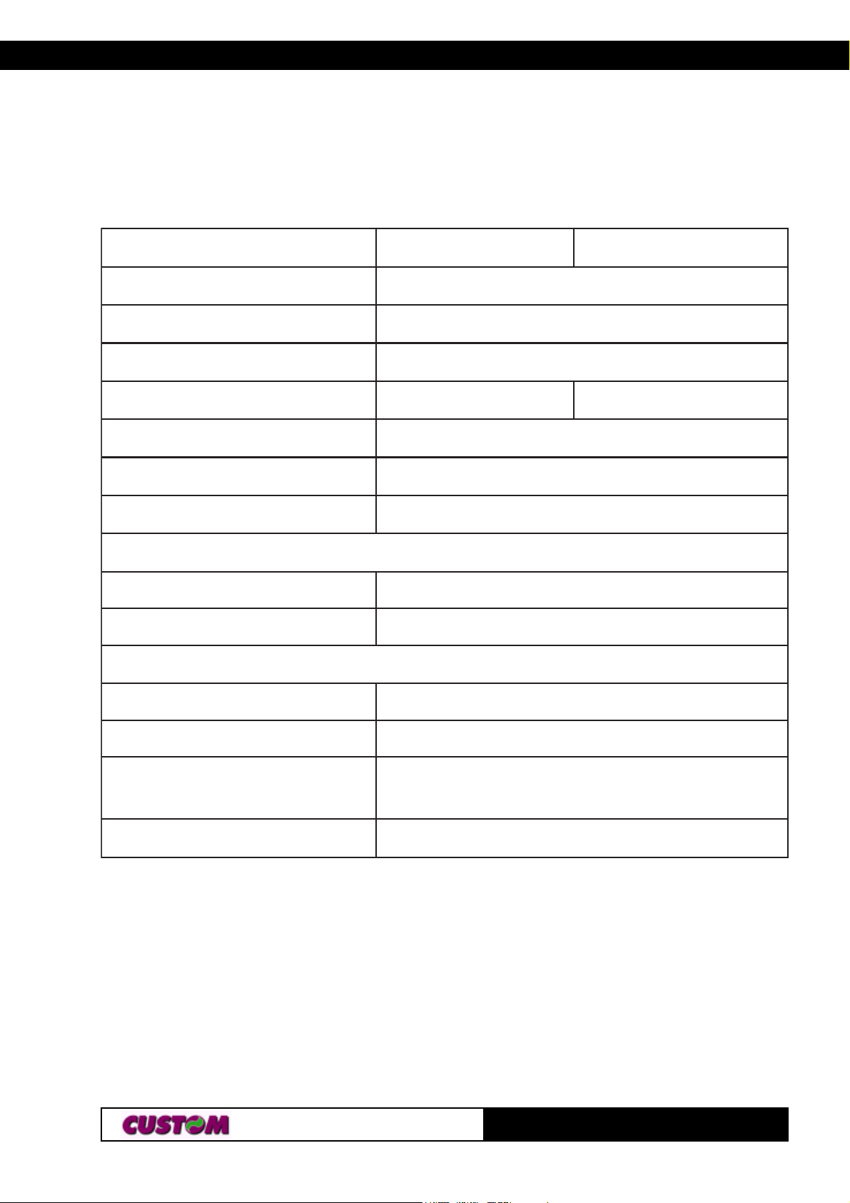
4. TECHNICAL DATA
4.1 TECHNICAL DATA
Table 4.1 lists the main technical features of the printer.
ledoMledoM
ledoMledoMT-53GTT-53GT
ledoM
noituloseRnoituloseR
noituloseRnoituloseR )mm/tod8(IPD002
noituloseR
deepsgnitnirPdeepsgnitnirP
deepsgnitnirPdeepsgnitnirP .ces/mm24
deepsgnitnirP
deepsdeefrepaPdeepsdeefrepaP
deepsdeefrepaPdeepsdeefrepaP .ces/mm06
deepsdeefrepaP
snoisnemidllorrepaPsnoisnemidllorrepaP
snoisnemidllorrepaPsnoisnemidllorrepaP mm53mm85
snoisnemidllorrepaP
secafretnidradnatSsecafretnidradnatS
secafretnidradnatSsecafretnidradnatS laireSLTT
secafretnidradnatS
T-53GTT-53GTT-85GTT-85GT
T-53GT
(Tab.4.1)
T-85GTT-85GT
T-85GT
secafretnilanoitpOsecafretnilanoitpO
secafretnilanoitpOsecafretnilanoitpO laireS232SR
secafretnilanoitpO
ylppusrewoPylppusrewoP
ylppusrewoPylppusrewoP %01-/+cdV21
ylppusrewoP
noitprosbAnoitprosbA
noitprosbAnoitprosbA
noitprosbA
gnitnirpnitnerruCA5.1
ybdnatsnitnerruCA5.0
snoitidnoclatnemnorivnEsnoitidnoclatnemnorivnE
snoitidnoclatnemnorivnEsnoitidnoclatnemnorivnE
snoitidnoclatnemnorivnE
erutarepmetgnitarepOC°05-C°0
ytidimuhevitaleR%58-%02
/erutarepmetegarotS
ytidimuH
snoitpOsnoitpO
snoitpOsnoitpO noitatpadaelbac232SR
snoitpO
/C°07+C°52-
%08-%01
14-
TG35/58-T
Page 48
4. TECHNICAL DATA
2
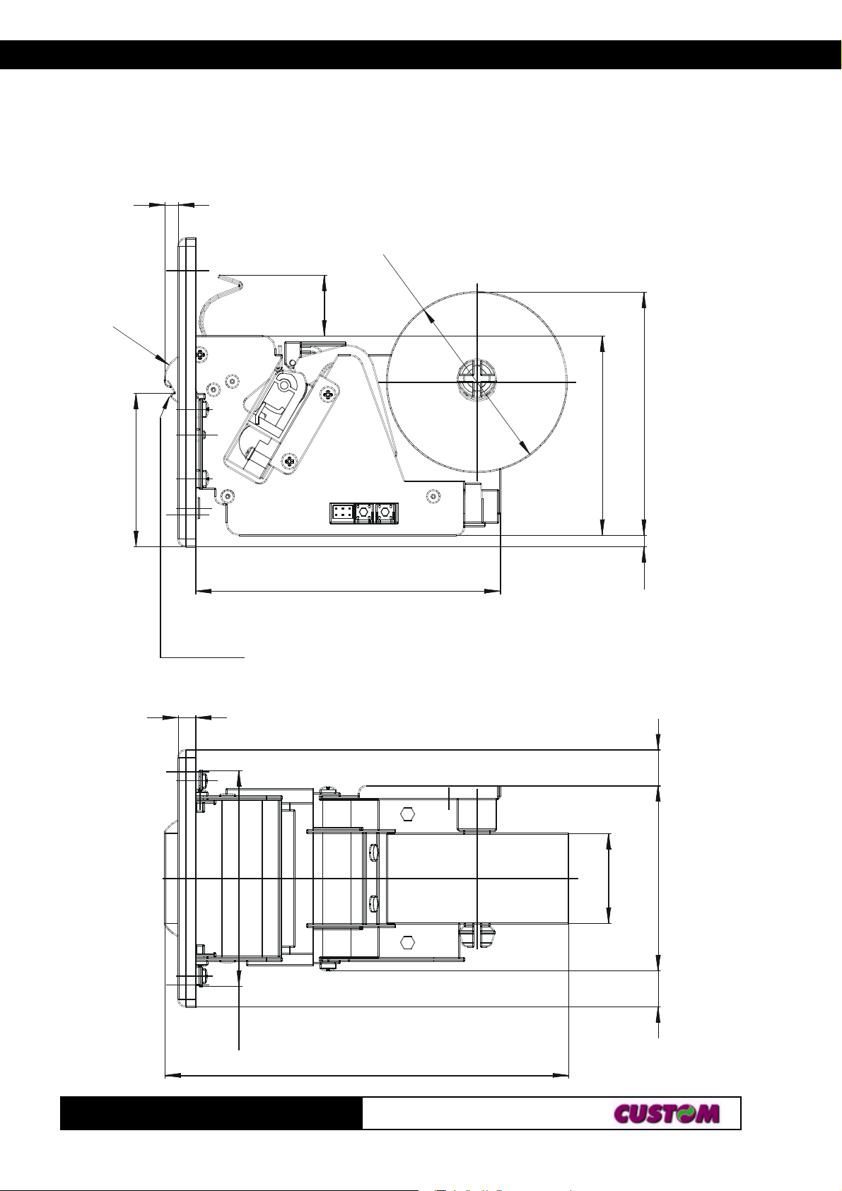
4.2 DIMENSIONS
The Figure 4.1 illustrates the overall dimensions for the TG35/58-T printer.
5.
ø
7
0
R
10
59.7
Carta
Paper
23.6
77.5
118.5
(Fig.4.1)
94.5
4.5
6.8
TG35/58-T
84
157
1414
35
72
24-
Page 49
4. TECHNICAL DATA
65
65
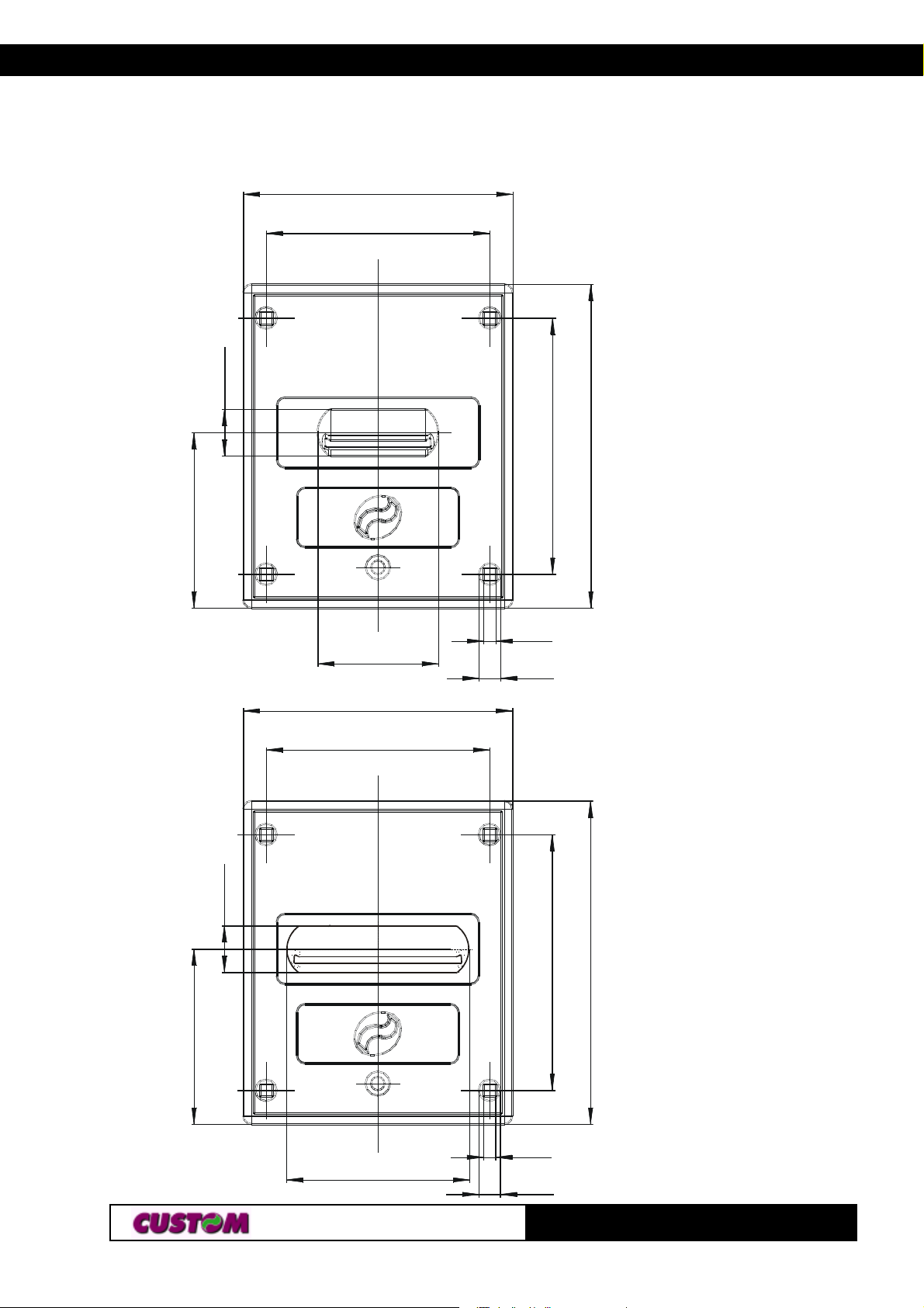
The Figures 4.2 and 4.3 illustrates the overall dimensions for the frontal
panel of TG35-T and TG58-T printer.
100
(Fig.4.2)
83
17.3
95
120
17.3
44.7
100
83
4.6
8ø
95
TG35-T frontal panel
(Fig.4.3)
120
67.7
TG58-T frontal panel
4.6
8ø
34-
TG35/58-T
Page 50
ATTACHMENT A - ACCESSORIES AND SPARE PARTS
A.1 ACCESSORIES
A.1.1 Power supply
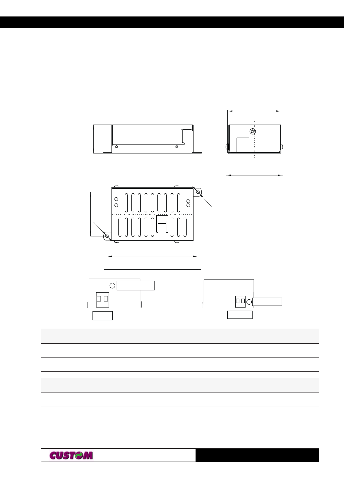
The following figure shows the 12V power supply, manufactured by Custom
Engineering, that can be used to operate the TG35/58-T printer.
66
(Fig.A.1)
35
70
(Tab.A.1)
3
.
5
54
3
.
5
112
120
GND chassis
N L
snoitacificepstupnIsnoitacificepstupnI
snoitacificepstupnIsnoitacificepstupnI
snoitacificepstupnI
0V 12V
egatlovtupnI caV042otcaV001
LED on
ycneuqerftupnIzH06otzH05
snoitacificepstuptuOsnoitacificepstuptuO
snoitacificepstuptuOsnoitacificepstuptuO
snoitacificepstuptuO
egatlovtuptuOV21
tnerructuptuOmumixaMA4
kaePA6
tiucriCtrohSA6
TG35/58-T1A-
Page 51
ATTACHMENT A - ACCESSORIES AND SPARE PARTS
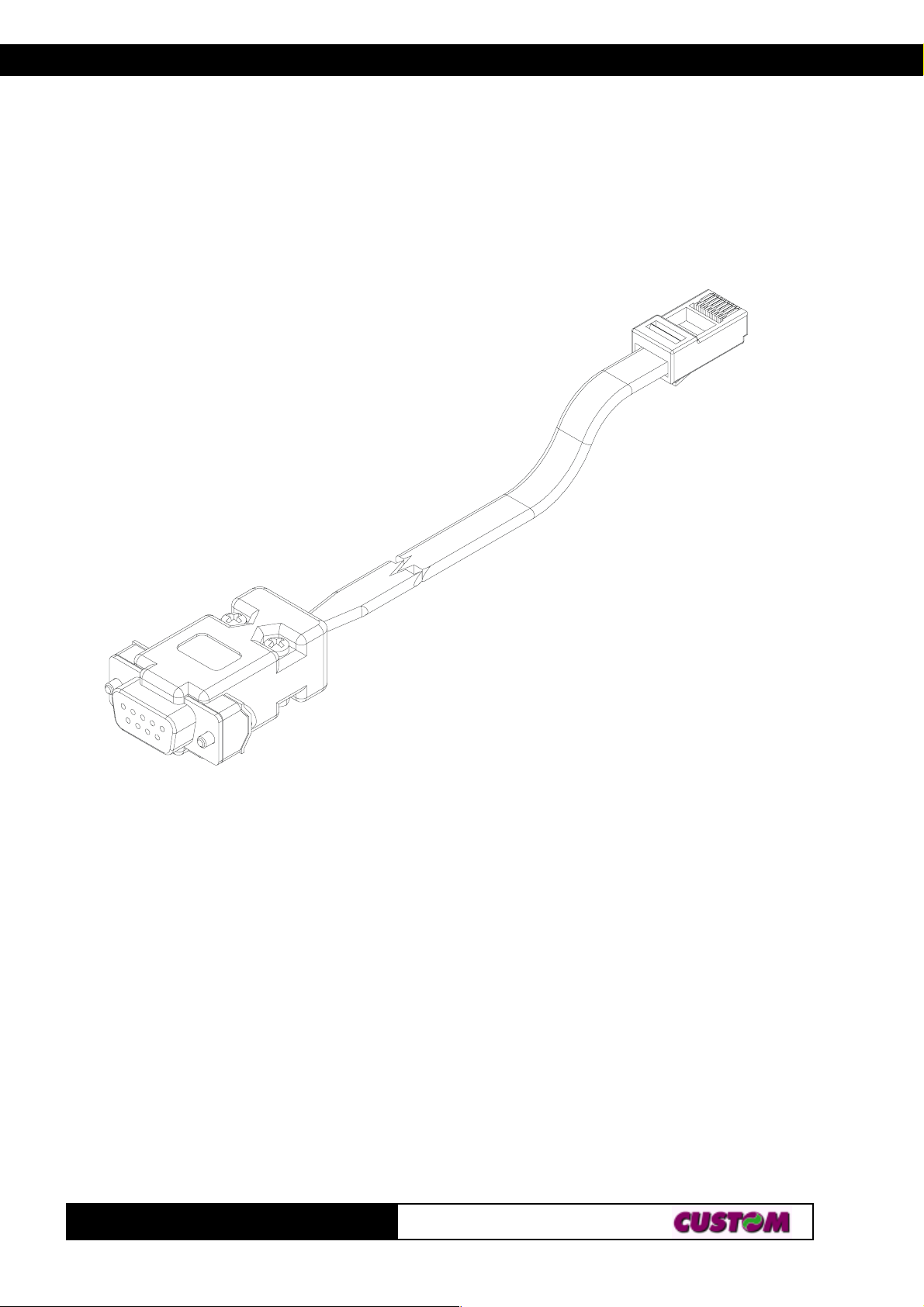
A.1.2 RS232 cable adaptation
There is an optional RS232 cable adapatation available for the printer that
consists in a double connection system (fig. A.2). On one side is a 9-pin
female connector for the serial port; on the other side of the same cable is a
RJ45 connector.
(Fig.A.2)
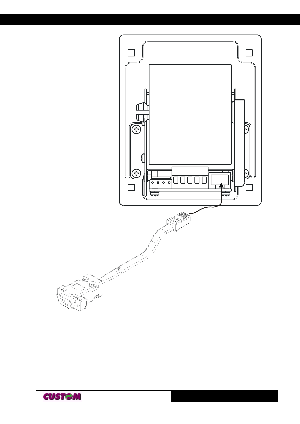
To connect the printer with the RS232 interface use this connection cable
and proceed as follows:
• connect the cable RJ45 connector to the J9 connector located at the back
of the printer (see fig. A.3);
• connect the 9-pin female connector (fig. A.3) to the serial port.
TG35/58-T 2A-
Page 52
ATTACHMENT A - ACCESSORIES AND SPARE PARTS
(Fig.A.3)
J9
TG35/58-T3A-
Page 53
ATTACHMENT A - ACCESSORIES AND SPARE PARTS
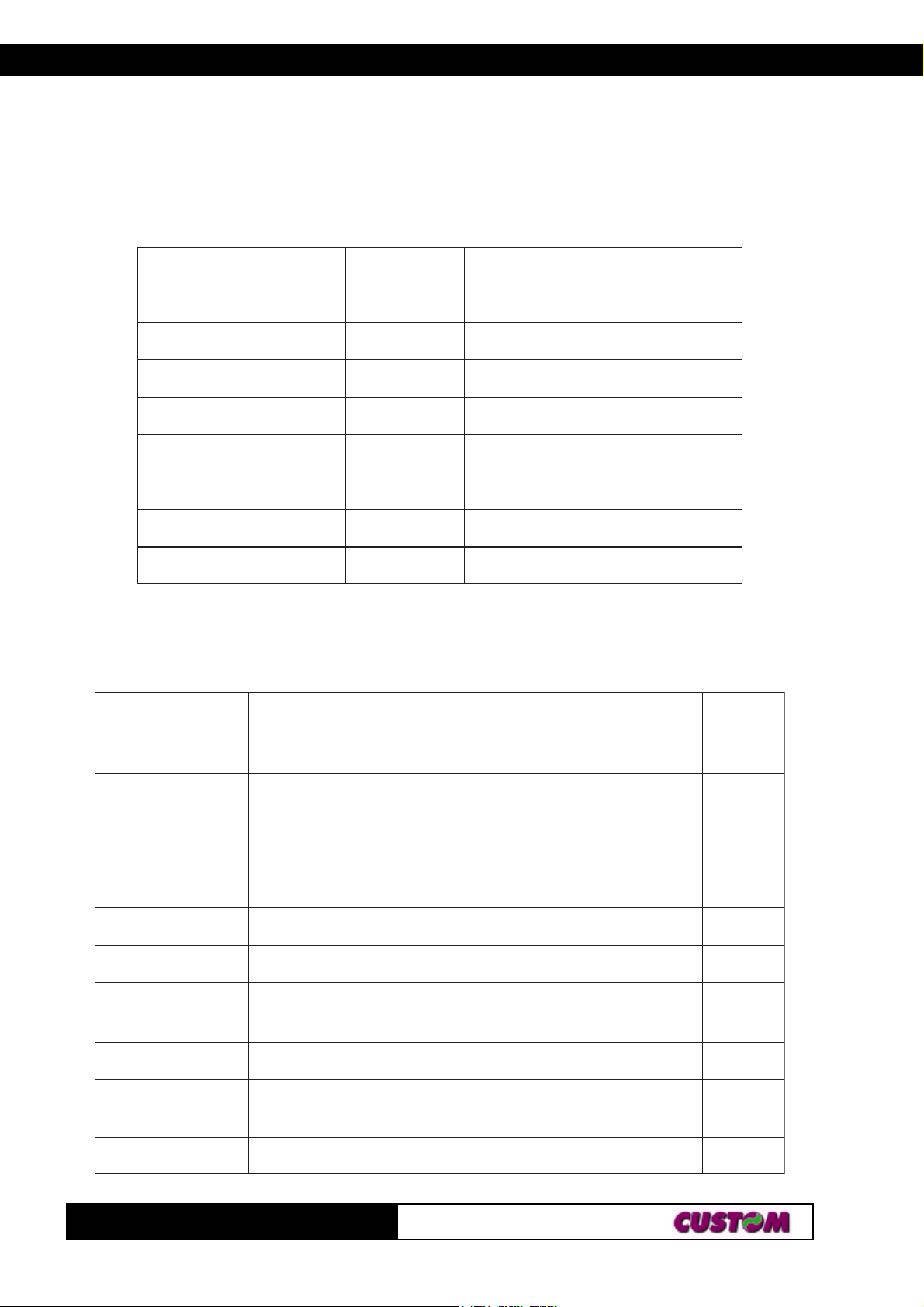
For the layout of signals on the connectors, please refer to tables A.2 and
A.3.
RJ45 cable connector (fig. A.3)
(Tab.A.2)
NIPNIP
NIPNIPLANGISLANGIS
NIP
LANGISLANGISTUO/NITUO/NI
LANGIS
TUO/NITUO/NINOITPIRCSEDNOITPIRCSED
TUO/NI
NOITPIRCSEDNOITPIRCSED
NOITPIRCSED
11111
22222
33333
44444
55555
66666
77777
88888
CCVTUOV5+
DNG- DNUORG
DXTTUONOISSIMSNARTATAD
DXRNINOITPECERATAD
STRTUODNESOTYDAER
NIV+TUOV21+
CN- DETCENNOCTON
CN- DETCENNOCTON
9-pin female cable connector (fig. A.3)
LANGISLANGIS
LANGISLANGIS
NIPNIP
NIPNIP
NIP
LANGIS
RETNIRP
NOITPIRCSEDNOITPIRCSED
NOITPIRCSEDNOITPIRCSEDTUO/NITUO/NI
NOITPIRCSED
(Tab.A.3)
TUO/NITUO/NI
TUO/NI
LANGISLANGIS
LANGISLANGIS
LANGIS
TSOH
EDIS
11111
22222
33333
44444
55555
66666
77777
88888
99999
DCD
XT
XR
.C.NdetcennoctoN-.C.N
DNGdnuorG-DNG
RTD
.C.NdetcennoctoN-.C.N
STR
.C.NdetcennoctoN-.C.N
ataD
ataD
TataD
)hgihlevel232SR
noitpeceR
lanimre
TG35/58-T 4A-
taevitca(nOretnirPtcetedreirraCataD
noissimsnarT
(tupnilaireS
dnanoretnirP.ydaeR
)gihlevel232SRtaevitca(gninoitcnuf
)hgihlevel232SRtaevitca(
)edisretnirP(tuptuolaireS
edisretnirP
)
noissimsnartatadrofydaeR.dnesotydaeR
TUODCD
TUOXR
NIXT
TUORSD
TUOSTC
Page 54
ATTACHMENT A - ACCESSORIES AND SPARE PARTS
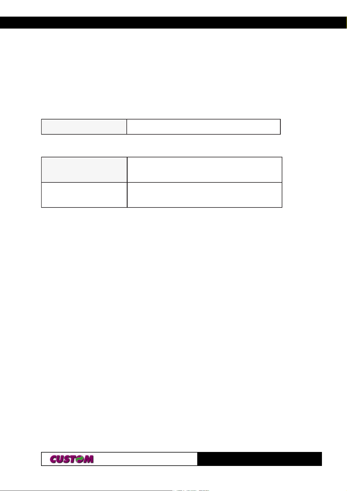
NOTE: In the table fig. A.3 Description and IN/OUT columns always are
related to signal printer
A.2 SPARE PARTS
FA-07X53TCRFA-07X53TCR
FA-07X53TCRFA-07X53TCR
FA-07X53TCR
gnitneverpduarfrepapllorlamrehT
(Tab.A.4)
(Tab.A.5)
ediskcabrepapllorlamrehT
SR-07X53TCRSR-07X53TCR
SR-07X53TCRSR-07X53TCR
SR-07X53TCR
detnirp-erp
0002rofogoldetnirp-erpdezimotsuC
muminimredrosllor
TG35/58-T5A-
 Loading...