

Page 1
USER GUIDE – REF. PSF-241
POWER SUPPLY/CHARGER – 24V DC 1 AMP UNIT
General
This power supply unit is for powering a 24V DC l amp load (750 mA load + 250mA charge). It also incorporates a
24V DC charger for use with Sealed Lead Acid Batteries up to 7ah. If the unit is being used to supply a load and
charge batteries, the total load should not exceed lamp. If the unit is being used to supply a load only, without standby
batteries, it is necessary to fit a resistor (value 10k ohm – ½ watt) across the battery terminal block instead of the
battery leads. The unit should be fitted in an upright position on a solid surface using the fixing holes provided.
The PSF-241 has a volt free relay fitted that will de-energise if any fault occurs
The PSU-400 has a volt free relay fitted that will de-energise on mains fail only.
Supply
PCB CONNECTIONS
Battery Output
Lid Indicators
PCB Fuses
F.1. Battery = 1 Amp F.2. = 1Amp
PCB Indicators
Amber (upper) = Short circuit fault/supply fault.
Amber (lower) = Charge output fault.
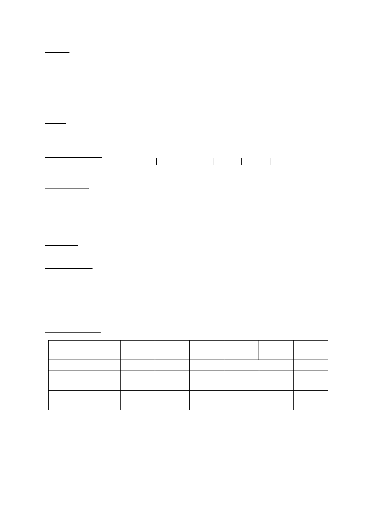
Fault Find Matrix
Supply to the unit should be 240V ac 50Hz and an earth should be fed to the unit via a 5amp-fused outlet
fitted adjacent to the unit. The mains supply in the enclosure should be wired into the fused terminal block
next to the PCB. The unit should be earthed.
0 0 0 0
+ - + -
Green = Supply Healthy Amber = Fault
When the Green light only is illuminated, the unit is operating normally with supply to the load and the
batteries (when fitted) are receiving charge current. When the Amber light is illuminated at the same time as
the Green light there is a fault on either or both of the output supply and the charge supply. If the Green light
is NOT illuminated, the mains supply is not present or the main “o verload” fuse has blown.
Upper indicator illuminated, this will be caused by either, a short circuit in the wiring, or an excessive load.
Lower indicator illuminated will be caused by blown fuse (bottom) in the battery charge output (i.e. Short
circuit of the battery leads) or by output supply short circuit. It is essential the battery is not fitted
“REVERSE POLARITY” as this will cause damage to the charging circuit which may be irreparable.
LED Green
LED Amber
PCB Upper
PCB Lower
Fault Relay: if fitted
Mains
ok
Y N Y Y Y Y
N N N Y N Y
N N N Y N N
N Y N N N Y
N Y N Y N Y
Mains
fault
Output
Ok
Output
fault
Charger
Ok
Charger
fault
User Guide – DOC-004g
 Loading...