

Page 1

AOV SINGLE ZONE CONTROL UNIT
Models AOV-001, AOV-003, AOV-005, AOV-007
http://www.aovcontrols.com
DOC- 140A
Installation Manual Index
1. Introduction
2. Supply
3. General operation
4. Specification
5. Preparation
6. Internal layout
7. Installing
8. Indicators – Lid Display
9. AOV Distribution PCB connections
10. Power Supply PSF-243 (3 Amp) or PSF-245 (5 Amp)
11. Power Supply PSF-249 (10 Amp)
12. Indicators AOV PCB
13. Actuator wiring
14. Detector wiring
15. Manual Call Point wiring
16. Firemans Switch wiring
17. Fire Alarm input wiring
18. Single zone schematic
19. Commissioning
20. Maintenance
1. Introduction
This control unit is for use with most Automatic Opening Vents and can
be used with other equipment that requires reverse voltage for closure. It
can be connected to most Fire Alarm systems operating on 24v dc. The
unit includes a 27.6V DC charger for use with Sealed Lead Acid Batteries
sized accordingly to up to 7Ah. The output load connected to the unit
should not exceed 1 Amp on AOV-001, 3 Amp on AOV-003, 5 Amp on
AOV-005 and 10A on AOV007 (excluding battery charging). .
2. Supply
Supply to the unit should be 240V ac 50Hz (+/-5%) and be fed via an
unswitched 5amp -fused spur outlet, fitted adjacent to the unit. The mains supply
in the enclosure should be wired into the fused terminal block provided. The unit
should be earthed.
3. General operation
With mains 240Vac connected the unit will charge batteries via the PSU
pcb (when fitted correctly) and will give an output of 24v DC +15%/-10%
when activated by Fire Alarm Control Panel or other control system.
When reset is effected at the Fire Panel the unit will reverse the polarity of
the output. Care must be taken that any equipment connected will not be
damaged by this operation.
Note: When reset is effected there will be timed reverse polarity output
irrespective of whether a trigger input from a Fire Panel or other device
is present or not.
SW1 provides a fire override feature to close the actuators, over riding any
trigger input.
This unit also has a fault-monitoring relay on the psu PCB. The relay is
energised when the unit is operating under normal (fault free) conditions
and gives a set of voltage free contacts at the ‘Fault Relay Output’. The
relay will operate in tandem with the main lid fault LED. These contacts
can be used to signal faults to a remote monitoring system or to control a
remote indicator or audible unit if required
Page 2
4. Specification
Input Voltage 240v AC 50Hz (+5% / -5%)
Output Voltage 24v DC (+20% / -10%)
Output Rating AOV-001 : 1amp AOV-003 : 3amp
AOV-005 : 5amp AOV-007 : 10amp
Battery Charge Current AOV-001 : 0.25amp AOV-003 : 0.50amp
AOV-005 : 0.75amp AOV-007 : 2.0amp
Battery Type Sealed Lead Acid
Enclosure Colour Grey RAL 7035
Enclosure Size 400mmW x 300mmH x 110mmD
Weight 7kgs – 9kgs
Optional
items
Break Glass Call Point
Smoke Detectors
Temperature sensors
Chain and Linear Actuators.
5. Preparation
After unpacking, the unit should be prepared for installation.
The lid is fixed to the body with 4 bolts and after removing these bolts the lid can
be lifted from the unit. There are no interconnecting cables between the lid and
the back-box, however, when the lid is finally refitted the earth cable between the
body and lid should be fitted.
The lid and screws should be carefully stored for refitting on completion of the
installation.
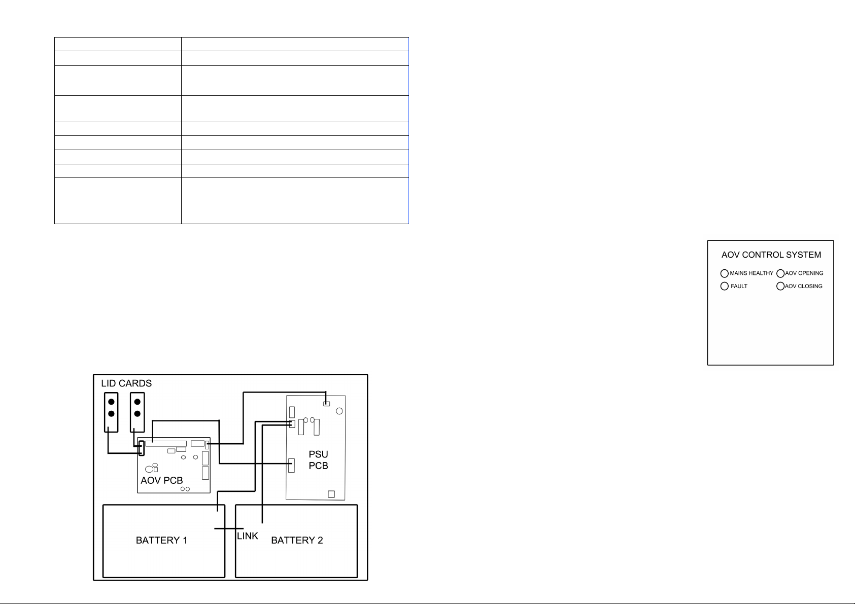
6. Internal layout
7. Installing
The unit should be fitted in an upright position on a solid surface using the
fixing holes provided. The unit mounting location should be selected to allow
space around the unit to aid heat dissipation. It should not be mounted adjacent to
any other source of excessive heat. There are 5 mounting points available in the
enclosure with a top central keyhole to allow the unit to hang whilst marking the
other mounting points as required.
The back-box also has rear “dimples” to allow for imperfect wall levels as well
as to create space for air circulation.
Screws and anchor fixings should be sufficient to support the unit according to
the structure to which it is affixed.
Cabling of suitable rating should be used along with the appropriate termination
glands and securely fixed via the knockouts provided.
8. Indicators – Lid facia
Green = Mains Healthy Green = AOV opening
Amber = Fault Amber = AOV closing
When the Green light only is illuminated, the unit is
operating normally with supply to the load and the
batteries (when fitted) are receiving charge current.
When the Amber light is illuminated at the same time
as the Green light there is a fault on either or both of
the output supply and the charge supply. If the Green
light is NOT illuminated, the mains supply is not
present
.
Page 3
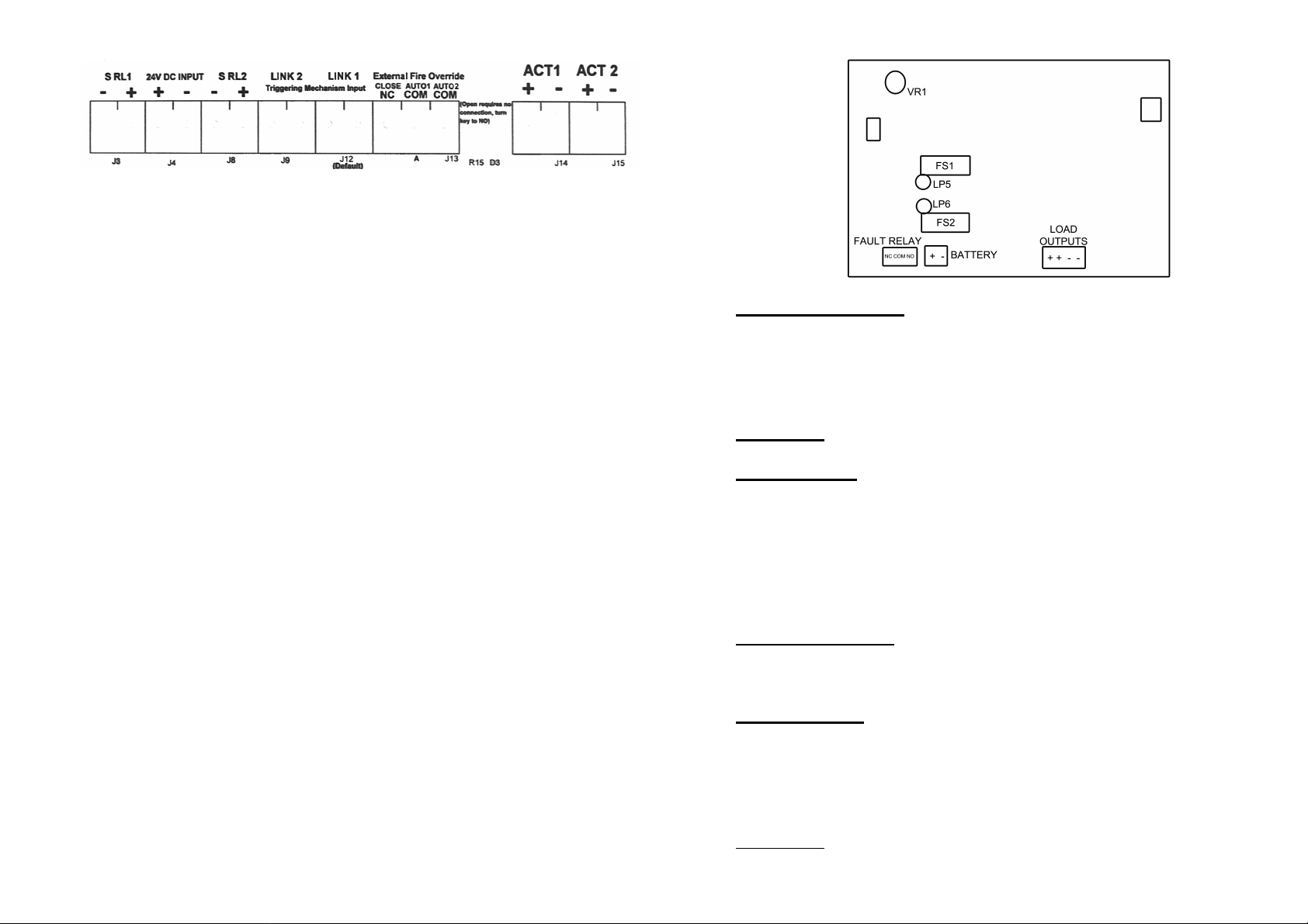
9. AOV distribution PCB connections
SRL1 – 24 v dc out only on closing 0 volts at all other times
24V DCINPUT – Input from Power Supply unit – observe polarity
SRL2 – 24vdc out continuously in quiescent 0 volts out on opening
LINK2 – Break closed link to get output volts from ACT 1 & ACT 2
Remake reverses.
LINK1 – Break closed link to get output volts from ACT 1 & ACT 2
Remake reverses.
EXT FIRE OVERRIDE – Connection for “Fireman’s” control if required
ACT1 +/- 24vdc output to actuator on system activation reverse voltage on
reset
ACT2 +/- 24vdc output to actuator on system activation reverse voltage on
reset
10. Power Supply – PSF-243 (3Amp) & PSF-245 (5 Amp)
Lid Indicators Green Green = Supply Healthy Amber = Fault
When the Green light only is illuminated, the unit is operating normally with supply to
the load and the batteries (when fitted) are receiving charge current. When the Amber
light is illuminated at the same time as the Green light there is a fault on either or both of
the output supply and the charge supply. If the Green light is NOT illuminated, the mains
supply is not present or the main “overload” fuse has blown.
PCB Fuses F.1. Battery = 3Amp quick blowF.2. = 3Amp quick blow
PCB Indicators
Amber (LP5) = Short circuit fault/supply fault.
Amber (LP6) = Charge output fault.
LP5 illuminated is either a short circuit in the wiring, or an excessive load.
LP6 illuminated is blown fuse (adj relay) in the battery charge output (i.e. Short circuit of
the battery leads) or by output supply short circuit. It is essential the battery is not fitted
“REVERSE POLARITY” as this will cause damage to the charging circuit which may be
irreparable.
Battery Connections
Two batteries (typical types to be used are Yuasa NP12-7) in equal state of charge are
required to make up 24V. The supplied leads should be used.
.
Battery Cut-Out
During A.C. failure the system will switch to battery standby, the output voltage level
will follow that of the batteries down to approximately 19V. At this point the cut-out
circuit for battery protection will disconnect power altogether. Should A.C. not be
available when testing with healthy batteries, a quick short on J11 pins will activate the
battery cut-in to power the load. (if there is sufficient charge in the batteries)
Fault Relay
The fault relay output will go from normal to fault state when A.C. power is removed or
when there's a fault in the unit as indicated by LP5 or LP6..
Page 4
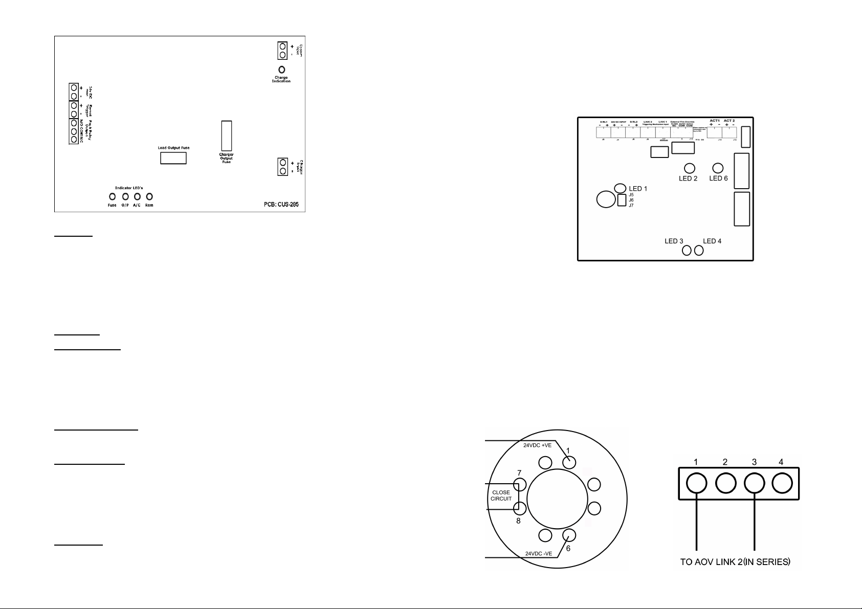
11. Power Supply Connections - PSF-249 (10 Amp)
Indicator Green = Supply Healthy Amber = Fault
12. Indicators – AOV pcb
Green LED 6 - Right hand relay pcb - lit in normal operation, off when “trigger”
present
Green LED 2 - Left hand relay pcb - lit when output 24v present
Green LED timer LED 1 - lit when timer is active upon actuator closure.
Green & Amber LED 3&4 – Actuator status.
When the Green light only is illuminated, the unit is operating normally with
supply to the load and the batteries (when fitted) are receiving charge current.
When the Amber light is illuminated at the same time as the Green light there is a
fault on either or both of the output supply and the charge supply. If the Green
light is NOT illuminated, the mains supply is not present.
PCB Fuse: FS.2. = 2 Amp (20mm x 5mm) Output Fuse: Standard automotive =10Amp
PCB Indicators:
Amber LED 5 = when lit indicates battery not connected or mains fail
Green LED 6 = when lit indicates ‘real’ battery charging in progress
Green LED 2 = when lit indicates the output is present.
Green LED 3 = when lit indicates the mains supply is present.
Amber LED 1 = when lit indicates there is an output fault/blown fuse.
Red LED 4 = when lit indicates there is a remote trigger input.
Battery Connections
Two batteries (typical types to be used are Yuasa NP12-7) in equal state of charge are
required to make up 24V. The supplied leads should be used.
Battery Cut-Out
During A.C. failure the system will switch to battery standby, the output voltage level
will follow that of the batteries down to approximately 19V. At this point the cut-out
circuit for battery protection will disconnect power altogether. Should A.C. not be
available when testing with healthy batteries, a quick short on J11 pins will activate the
battery cut-in to power the load. (if there is sufficient charge in the batteries)
Fault Relay
The fault relay output will go from normal to fault state when A.C. power is removed or
when there's a fault in the unit as indicated by LP5 or LP6..
13. Actuator timing setup
Using the jumper provided, junctions J5, J6 and J7 will provide the following
time scales when in reverse polarity:
J7 = 0 seconds – 1 minute
J6 = 1 minute – 2 minutes
J5 = 2 minutes – 3 minutes
Note: These time scales are adjusted using VR1
14. Detector wiring 15. MCP (“Smash Glass”) wiring
Page 5
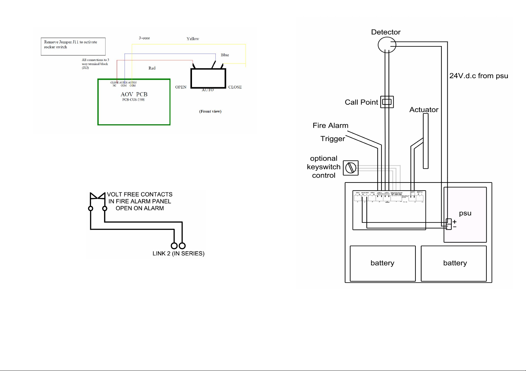
16. Connection to Firemans Switch
17. Fire Alarm input wiring
18. System schematic for single zone
Page 6

19. Commissioning
1. When all parts of the system have been installed final connecting
and testing can be started.
2. It is recommended that all parts of the system to be wired into the
control panel are tested separately and independently before
connecting into the control panel. Any parts not working correctly
must be rectified before proceeding.
(The SLA batteries to be used in the control unit can be used to test
actuators for forward and reverse action before connecting into
control panel. Other volt free items can be checked with a multimeter before final connection)
3. The mains input should be connected first into the power supply
mains terminal block. After checking that any bare cable ends are
clear of circuit boards the unit can be switched on. When switched
on the relays on both main PC boards will “click” and LEDs will
light up:
Amber on power supply PCB
Green and amber on AOV PCB
Green and amber on lid cards
4. After 40 to 50 seconds when the AOV timers have reset there
should be:
one green LED illuminated on AOV PCB
one amber LED illuminated on power PCB
Green and amber illuminated on left lid card
5. Now connect the SLA batteries 2 x 12volt in series to make a
24volt set. Then connect the battery set into the battery terminals
on the PSU PCB taking particular care to get the correct polarity.
6. After connecting the batteries there should be only the green LED
illuminated on the left lid card.
7. At this point the rest of the system components should be added
one at a time testing the performance as each part is connected. If
there is a problem in the wiring of one of the parts it will show up
when tested and can be rectified immediately.
8. Once all of the parts are connected successfully the system as a
whole can be tested:
Check that each smoke detector operates correctly and operates the
correct actuator(s).
Check that each call point operates correctly and operates the
correct actuator(s)
Check that the “Firemans switch” operates correctly.
Check that each actuator operates as required.
9. Once the testing has been satisfactorily completed the system
should be tested again with the mains supply to the unit switched
off. The system should still operate as before if the batteries are in
new condition. If not then switch on mains refit the lid and leave
the unit for 24 hours for the batteries to charge and then retest.
20. Maintenance
The AOV control panels do not require any specific maintenance other
than replacement of the Sealed Lead Acid batteries that generally have a
4-5 year life from new.
These batteries should be performance checked annually as a minimum
and tested on a regular basis for operation by switching off the mains to
the unit. If the batteries are in good condition they should be able to
operate the system with the mains off.
Any problem should be rectified immediately
The system should be checked regularly for continued performance by
testing each of the connected parts.
 Loading...